Adriana Maria Teles Sampaio
[Nome completo do autor]
[Nome completo do autor]
[Nome completo do autor]
[Nome completo do autor]
[Nome completo do autor]
[Nome completo do autor]
[Nome completo do autor]
Bachelor Degree in Chemical and Biochemical Engineering
Dissertação para obtenção do Grau de Mestre em
[Engenharia Informática]
Biogas production and purification using
membrane processes
[Título da Tese]
Dissertation to obtain Master Degree in Chemical and Biochemical Engineering
Dissertação para obtenção do Grau de Mestre em
[Engenharia Informática]
Supervisor: Doutora Luísa A. Neves, Investigadora Auxiliar, FCT-UNL Co-supervisor: Doutora Mónica Carvalheira, Investigadora, FCT-UNL
September 2019
Jury:
President: Professor Doutor Mário Fernando José Eusébio Supervisor: Doutora Luísa Alexandra Neves
III
Faculty of Sciences and Technology
NOVA University of Lisbon
September 2019
Adriana Maria Teles Sampaio
[Nome completo do autor]
[Nome completo do autor]
[Nome completo do autor]
[Nome completo do autor]
[Nome completo do autor]
[Nome completo do autor]
[Nome completo do autor]
Bachelor Degree in Chemical and Biochemical Engineering
Dissertação para obtenção do Grau de Mestre em [Engenharia Informática]
Biogas production and purification using
membrane processes
[Título da Tese]
Dissertation to obtain Master Degree in Chemical and Biochemical Engineering
Dissertação para obtenção do Grau de Mestre em
[Engenharia Informática]
Supervisor: Doutora Luísa A. Neves, Investigadora Auxiliar, FCT-UNL Co-supervisor: Doutora Mónica Carvalheira, Investigadora, FCT-UNL
Jury:
President: Professor Doutor Mário Fernando José Eusébio Supervisor: Doutora Luísa Alexandra Neves
V
Biogas production and purification using membrane processes
Copyright © Adriana Maria Teles Sampaio, Faculdade de Ciências e Tecnologia, Universidade Nova de Lisboa.
A Faculdade de Ciências e Tecnologia e a Universidade Nova de Lisboa têm o direito, perpétuo e sem limites geográficos, de arquivar e publicar esta dissertação através de exemplares impressos reproduzidos em papel ou de forma digital, ou por qualquer outro meio conhecido ou que venha a ser inventado, e de a divulgar através de repositórios científicos e de admitir a sua cópia e distribuição com objectivos educacionais ou de investigação, não comerciais, desde que seja dado crédito ao autor e editor.
VII
Agradecimentos
Finalmente chega ao fim uma das experiências mais importantes e enriquecedoras da minha vida e não poderia deixar de agradecer a todos aqueles que sempre me apoiaram incondicionalmente, que me deram força para continuar e que nunca me deixaram baixar os braços.
Gostaria de agradecer às minhas orientadoras, Luísa Neves e Mónica Carvalheira pela oportunidade de me integrar em dois grupos, BIOENG e LMPgroup e de poder aprender um pouco do mundo de membranas e de bioengenharia.
Um agradecimento muito especial ao Bruno Oliveira, que me acompanhou no laboratório de BIOENG desde o primeiro dia e que foi das pessoas que mais coisas me ensinou durante a realização desta tese.
Gostaria também de agradecer às pessoas integrantes do grupo de LMP que tive a oportunidade de conhecer e de conviver diariamente. Agradeço à Rita Nabais, por todo o tempo que passou comigo no laboratório no início desta tese, por tudo o que me ensionou e pela paciência que teve em me explicar muitas das coisas que sei de membranas. À Rosa Nascimento quero muito agradecer pela ajuda e pela boa disposição que diariamente me transmitiu.
À doutora Claudia Pereira queria agradecer a disponibilidade, simpatia e ajuda que me deu na síntese e caracterização do MOF.
A todos os meus amigos que me apoiaram durante estes anos, Rita Freitas, Diogo Boto, Beatriz Nobre e Tiago Ferreira mesmo não estando presentes diariamente sei que sempre me apoiaram e torceram por mim. Às minhas melhores amigas, Marta Bexiga, Carolina Cravalho, Sara Coutinho e Carolina Marques nem sei como agradecer todo o apoio e força que me deram, sem elas teria sido impossível! À Ana Patrícia quero muito agradecer por me ter encorajado a continuar e a enfrentar todos os obstáculos que surgiram ao longo destes meses.
Ao meu namorado, André Santos, quero agradecer todo o carinho, amor e paciência que teve comigo, a amizade sem fim, as manhãs, tardes e noites que teve ao meu lado.
À tia Carla e tio Vivi quero agradecer todo o carinho e apoio que me deram.
Por fim, quero agradecer aos meus pais, sem eles nada disto seria possível. Obrigada por me terem proporcionado a maior experiência da minha vida, por terem acreditado que seria capaz e por terem investido no meu futuro! Ao meu irmão que sempre me deu força para não desistir e que está, até hoje, à espera de um jantar pago com o meu primeiro ordenado. Às minhas primas Bárbara, Amora e Benedita e à minha tia Isabel quero agradecer por terem sempre acreditado em mim, por todas as velinhas que acenderam e por todas as palavras de coragem que me deram. Aos meus avós, Manuel Trindade e Maria de Matos por todo o carinho e amor que me deram desde sempre. E por último quero muito agradecer aos meus dois anjinhos, Avó Perpétua e Avô Horácio que mesmo não estando presentes fisicamente estiveram e estarão sempre a olhar por mim!
IX
Abstract
In this master thesis, a single-stage anaerobic co-digestion system was operated treating a mixture of leachate and tannery wastewater, increasing salinity from 5 to 15 g Na+ L-1.
Biogas production (1.6 ± 0.3 – 3.0 ± 0.3 L d-1) increased as salinity increased up to 10 g Na+ L-1 as well as CH4 yield (0.29 ± 0.03 – 0.33 ± 0.03 L CH4 g-1 COD). At 15 g Na+ L-1, a decrease in biogas production and granules fragmentation were observed. Overall, the results showed that the microbial community was able to withstand salinities up to 15 g Na+ L-1, presenting a good performance on the co-treatment of leachate and tannery wastewater.
The second part of this master thesis was focused on the effect of combining metal organic frameworks (MOF-5), with high adsorption properties towards CO2 when compared with CH4, with a combination of different poly(ionic liquid)/ionic liquid (PIL/IL) membranes for biogas upgrading. The MOF-5 was incorporated at different loadings (10, 20 and 30 wt%), and mixed matrix membranes (MMMs) were prepared by solvent evaporation method. The results showed that MOF-5 particles were uniformly dispersed into the PIL/IL matrix, except for PIL C(CN)3/40 [C2MIM][C(CN)3]. The prepared PIL/IL/MOF-5 membranes revealed suitable thermal stability (Tonset up to 300-380ºC) for biogas upgrading, but a loss of mechanical stability was found after the incorporation of MOF-5. Nevertheless, increasing MOF-5 content in the MMMs resulted in an improvement on CO2 permeability, which increased 133% for PIL Tf2N/40 [C2MIM][BETi]/30 MOF-5 when compared to PIL Tf2N/40 [C2MIM][BETi]. It was therefore possible to demonstrate the improvement of CO2/CH4 separation performance of this MMMs system using MOF-5, which opens the perspective of using these materials for biogas upgrading.
Keywords: single-stage anaerobic co-digestion system; biogas; salinity; biogas upgrading; mixed
XI
Resumo
Nesta dissertação foi desenvolvido um sistema de co-digestão anaeróbia de uma fase por forma a tratar uma mistura de lixiviados e curtumes através do aumento da salinidade de 5 a 15 g Na+ L-1. A produção de (1.6 ± 0.3 – 3.0 ± 0.3 L d-1) aumentou com o aumento da salinidade até 10 g Na+ L-1, bem como o rendimento de metano (CH4) (0.29 ± 0.03 – 0.33 ± 0.03 L CH4 g-1 COD). A 15 g Na+ L-1, foi observada uma diminuição da produção de biogás bem como a fragmentação dos grânulos. No geral, os resultados mostraram que a comunidade microbiana foi capaz de suportar salinidades de até 15 g Na+ L-1, apresentando um bom desempenho no co-tratamento de lixiviados e curtumes.
A segunda parte desta dissertação focou-se no efeito da combinação de redes (metal-organic
frameworks) (MOF-5), com elevadas propriedades de adsorção em relação do CO2 quando comparado com o CH4, com diferentes membranas constituídas por líquidos iónicos poliméricos/líquidos iónicos (PIL/IL) para a purificação do biogás. Após a incorporação de diferentes concentrações de MOF-5 (10, 20 e 30 p/p%), as membranas de matriz mista (MMMs) foram preparadas pelo método de evaporação de solvente. Os resultados mostram que as partículas de MOF-5 foram uniformemente dispersas na matriz PIL/IL, exceto para a membrana PIL C(CN)3/40 [C2MIM][C(CN)3]. As membranas PIL/IL/MOF-5 preparadas revelaram uma estabilidade térmica adequada (Tonset entre 300-380 ºC) para a purificação do biogás, apesar da perda de estabilidade térmica após a incorporação de MOF-5. No entanto, o aumento da quantidade de MOF-5 nas MMMs resultou numa melhoria na permeabilidade do CO2, que aumentou 133% para a PIL Tf2N/40 [C2MIM][BETi]/30%MOF-5 quando comparada à PIL/IL. Desta forma, foi possível melhorar o desempenho da separação de CO2/CH4 deste sistema de MMMs através da utilização de MOF-5, o que permite a sua utilização para a purificação do biogás.
Palavras chave: Sistema de co-digestão anaeróbia de uma fase; biogás; salinidade; purificação do
XIII
List of contents
1. Introduction ... 1
1.1. Problem statement ... 1
1.2. Anaerobic digestion process ... 2
1.2.1. Microbiological aspects and main pathways of anaerobic digestion ... 3
1.2.2. Single-Stage anaerobic digestion system ... 4
1.2.3. Operational and environmental conditions ... 5
1.3. Biogas Upgrading ... 7
1.3.1. Technologies for biogas upgrading ... 7
1.3.1.1. Absorption ... 7
1.3.1.2. Pressure Swing adsorption (PSA) ... 9
1.3.1.3. Cryogenic separation ... 9
1.3.1.4. Membrane separation ... 9
1.4. Objectives of this thesis ... 14
2. Materials and methods ... 15
2.1. Operation of a single-stage anaerobic digestion system ... 15
2.1.1. Materials ... 15
2.1.1.1. Substrate and inoculum ... 15
2.1.1.2. Experimental Setup and operation ... 15
2.1.2. Analytical methods ... 16
2.1.3. Parameters calculation ... 18
2.2. Biogas upgrading using MMMs with MOFs ... 20
2.2.1. Materials ... 20
2.2.2. Methods ... 21
2.2.2.1. MOF-5 synthesis and characterization ... 21
2.2.2.2. Preparation of PIL-IL composite membranes ... 22
2.2.2.3. Preparation of PIL/IL/MOF-5 mixed matrix membranes ... 22
2.2.2.4. Scanning Electron microscopy (SEM) ... 23
2.2.2.5. Fourier Tranform Infrared Spectroscopy (FTIR) Analysis ... 23
2.2.2.6. Contact Angle ... 23
2.2.2.7. Termogravimetric Analysis (TGA) ... 23
2.2.2.8. Mechanical properties ... 24
2.2.2.9. Gas permeation experiments ... 25
3. Results and discussion ... 29
3.1. AD operation ... 29
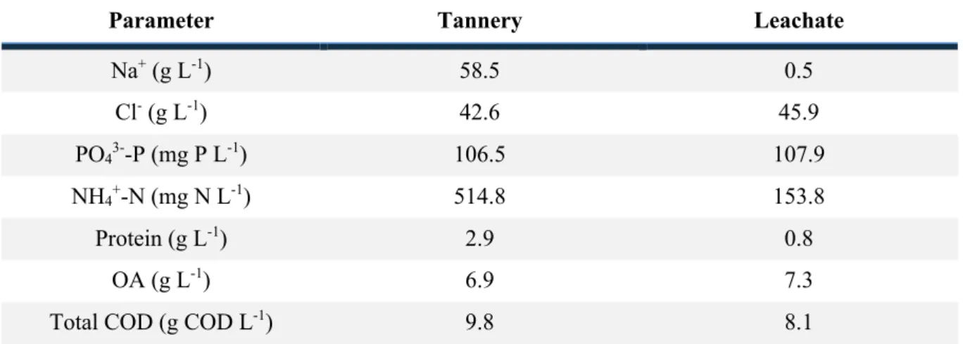
3.1.1. Leachate and tannery characterization ... 29
3.1.2. Overall process efficiency ... 30
3.1.2.1. Consumption of organic acids and COD removal ... 30
3.1.2.2. Granules integrity and biomass concentration ... 32
3.1.2.3. Biogas production and composition ... 33
3.1.2.4. Nutrients concentration ... 35
3.2. Biogas upgrading – Performance assessment of MMM’s with MOF-5 on CO2/CH4 separation ... 36
3.2.1. MOF-5 characterization ... 36
3.2.1.1. Powder X-ray diffraction (PXRD) ... 36
XIV
3.2.2.1. Scanning Electron microscopy (SEM) ... 37
3.2.2.2. Fourier Transform Infrared Spectroscopy (FTIR) analysis ... 40
3.2.2.3. Contact Angle ... 42
3.2.2.4. Termogravimetric analysis (TGA) ... 43
3.2.2.5. Mechanical properties ... 45
3.2.2.6. Gas permeation experiments ... 47
4. Conclusions ... 51
5. Future work ... 53
XV
List of figures
Figure 1. 1. Examples of wastes which can be anaerobically digested to produce biogas ... 2
Figure 1. 2. Stages of anaerobic digestion process and the different bacterial group involved ... 4
Figure 1. 3. Schematic representation of membrane separation ... 10
Figure 1. 4. Schematic representation of the relationship between selectivity and permeability with the Robeson upper bound ... 11
Figure 1. 5. Upper bound correlation between CO2 and CH4 ... 12
hjhjjhkjkhkjjjh Figure 2. 1. Schematic representation of the single-stage anaerobic system ... 15
Figure 2. 2. Structure of MOF-5 ... 21
Figure 2. 3. Schematic representation of the single gas permeation installation ... 25
asasasas Figure 3. 1. Concentration of OA in influent and reactor obtained for each condition tested. ... 31
Figure 3. 2. COD variation in the feed and reactor and COD removal ... 32
Figure 3. 3. VSS concentration in the reactor at different heights from the bottom of the reactor ... 33
Figure 3. 4. Biogas production, CH4 production and gas volume over time. ... 33
Figure 3. 5. Biogas composition produced in the UASB reactor in each salinity tested ... 34
Figure 3. 6. Phosphorus and amomonia concentrations in the influent and in the reactor ... 35
Figure 3. 7. PXRD pattern of the synthesised MOF-5. ... 36
Figure 3. 8. Obtained FT-IR spectra of the studied MOF-5, [C2MIM][BETi] IL, [pyr11][Tf2N] PIL, PIL Tf2N/40 [C2MIM][BETi] and MMMs with different MOF-5 loadings ... 41
Figure 3. 9. Obtained FT-IR spectra of the studied MOF-5, [C2MIM][C(CN)3] IL, [pyr11][C(CN)3] PIL, PIL C(CN)3/40 [C2MIM][C(CN)3] and MMMs with different MOF-5 loadings ... 42
Figure 3. 10. Weight loss as a function of temperature of PIL Tf2N/40 [C2MIM][BETi]; MOF-5; PIL Tf2N/40 [C2MIM][BETi]/10 MOF-5; PIL Tf2N/40 [C2MIM][BETi]/20 MOF-5; PIL Tf2N/40 [C2MIM][BETi]/30 MOF-5 ... 44
Figure 3. 11. Weight loss as a function of temperature of PIL C(CN)3/40 [C2MIM][C(CN)3]; MOF-5; PIL C(CN)3/40 [C2MIM][C(CN)3]/10 MOF-5; PIL C(CN)3/40 [C2MIM][C(CN)3]/20 MOF-5; PIL C(CN)3/40 [C2MIM][C(CN)3]/30 MOF-5 ... 45
Figure 3. 12. CO2/CH4 PIL/IL ideal selectivity as a function of CO2 permeability ... 47
Figure 3. 13. Evolution of CO2 of PIL Tf2N/40 [C2MIM][BETi] membranes permeability as a function of MOF-5 loading ... 48
XVII
List of tables
Table 1. 1. Typical composition of biogas ... 3
Table 1. 2. Solubility, in kg of CO2 per kg of water at different temperatures ... 8
asaafasdfsd Table 2. 1. Operational conditions used in the reactor. ... 16
Table 2. 2. Reagents used in protein protocol ... 17
Table 2. 3. Properties results of the ionic liquids used ... 20
Table 2. 4. Chemical and physical properties of MOF-5 ... 21
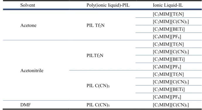
Table 2. 5. Solvents, PIL and IL used to composite membrane preparation ... 22
sdasfsdfsd Table 3. 1. Characterization of the different wastewaters treated in the single-stage AD system ... 29
Table 3. 2. Reactor performance (COD removal and biogas parameters) under different salinities ... 30
Table 3. 3. Combinations of solvents, PIL and IL used in the prepared PIL/IL composite membranes and the results of PIL/IL membranes preparation ... 37
Table 3. 4. SEM images of PIL Tf2N/40 [C2MIM][BETi]/MOF-5 (0, 10, 20 30 wt%) membranes .... 38
Table 3. 5. SEM images of PIL C(CN)3/40 [C2MIM][C(CN)3]/MOF-5 (0, 10, 20 30 wt%) membranes ... 39
Table 3. 6. Water contact angles of the PIL Tf2N/40 [C2MIM][BETi] membrane, as well as their MMMs with different MOF-5 loadings ... 43
Table 3. 7. Thermal properties of the PIL Tf2N/40 [C2MIM][BETi] membrane, as well as their MMMs with different MOF-5 loadings ... 43
Table 3. 8. Puncture test results of PIL Tf2N/40 [C2MIM][BETi]/MOF-5 membranes ... 46
Table 3. 9. Puncture test results of PIL C(CN)3/40 [C2MIM][C(CN)3]/MOF-5 membranes ... 46
XIX
List of Abbreviations
AD Anaerobic digestion COD Chemical oxygen demand CSP Chemical scrubbing process CSTR Continuous stirred-tank reactor DEA Diethanolamine
DMF Dimethylformamide
EGSB Expanded granular sludge bed
FTIR Fourier Tranform Infrared Spectroscopy
GC Gas chromatography
HAc Acetic acid HBut Butyric acid HIsoB Isobutiric acid HIsoV Isovaleric acid HPr Propionic acid
HPWS High pressure water scrubbing HRT Hydraulic retention time HVal Valeric acid
IL Ionic liquid
MDEA Methyldiethanolamine MEA Monoethanolamine MMM Mixed matrix membrane MOF Metal organic framework
OA Organic acid
OLR Organic loading rate OPS Organic physical scrubbing PIL Poly(ionic liquid)
PSA Pressure swing adsorption
PZ Piperazine
SCOD Soluble chemical oxygen demand SEM Scanning Electron Microscopy TGA Thermogravimetric analysis TSS Total suspended solids
UASB Upflow anaerobic sludge blanket VFA Volatile fatty acid
XX VSS Volatile suspended solids
Cations [C2MIM] 1-ethyl-3-methylimidazolium [C4MIM] 1-butyl-3-methylimidazolium Polycation [py11] Poly(diallyldimethylammonium Anions [Tf2N] Bis(trifluoromethylsulfonyl)imide [BETi] Bis(pentafluoroethylsulfonyl)imide [C(CN)3)] Tricyanomethanide [PF6] Hexafluorophosphate
XXI
List of variables
A Membrane area l Membrane thickness P Permeability p Pressurepfeed Pressure in feed compartment
pperm Pressure in the permeate compartment
Q Flow rate
t Time
Tdec Decomposition temperature Tonset Onset temperature
Vfeed Volume of the feed compartment Vperm Volume of the permate compartment a Ideal selectivity
Biogas production and purification using membranes processes 1
1.
Introduction
1.1.
Problem statement
Nowadays, the increase of the industrialization, as a consequence of economic growth, resulted in the generation of a huge quantity of wastes from several sources such as municipal, industrial and agricultural.1 Usually, these wastes and other solid wastes are disposed and treated using conventional treatment methods, where landfill is one of the most and widely technology used.2
In landfills, where are mainly collected municipal wastes, occurs the decomposition of organic matter resulting in a wastewater known as leachate and gases that contributes to 20% of the global methane emissons.3 Leachate from landfills contain typicaly both simple and complex components, such as, high organic matter content, salts and ammonia and their accumulation in environment is a huge problem since causes several pollution problems, namely contamination of soil, surface and groundwater.4–6 Despite these disadvantages, landfills still remains the most used alternative to dispose wastes.7
Some industries, such as seafood, petroleum and leather industries, produce saline effluents with high organic content and high amounts of salt.4,8 Leather industries involves the addition of salt in the tanning process that occurs through several steps and where raw hides and skins are transformed in finished leather products. The tanning process involves high quantities of water in each step, producing hypersaline streams, such as pickling wastewater, and the soak liquor generated by the soaking of hides and skins containing, sometimes, about 80g L-1 of NaCl.4 The discharge of these type of effluents in the environment without pre-treatment leads to the contamination of agriculture fields, water potability and aqualife. The use of physico-chemical methods to treat saline effluents is the alternative currently used; however presents several disadvantages, namely high energy consumption and high running costs. Another alternatives are discharge saline effluents to the seaside, that is not feasible, and desalination by reverse osmosis, that is very expensive.9 In the last 10 years the interest in wastewaters with high sanility has been increasing due to the dimension of this problem.4 Biological processes are developed as an alternative but the high salinity of this type of wastes effect negatively the process.
Taking into account the problems associated with current treatment strategies, the development of economic and environmental treatment technologies is crucial.
In this context, the present linear economic model of “take-make-consume-dispose” is being slowly substitute by circular economy, with a sustainable approach focused in maintain and retain the value of materials and products.10 Therefore, the treatment of wastes and wastewater with resources recovery through an integrated system offers an economic and versatile way for a global sustainable development. Examples of these systems include the production of biopolymers and biogas from anaerobic digestion.11
Anaerobic digestion (AD) has been studied in recent years as a suitable technology and an energy-efficient process for biological waste treatment with high benefits, such as waste reduction and biogas
Biogas production and purification using membranes processes 2 production.12 Therefore, AD is reviewed as a promising sustainable solution that will not only reduce the negative impacts of wastes accumulation, mentioned above, but also generate an alternative to the current increase of fossil fuels consumption, producing methane-rich biogas, which can be used as a renewable source of energy. The production of biogas through anaerobic digestion was considered as one of the most efficient and environmental beneficial technology for bioenergy production.13 However, several factors such as, organic carbon, nutrients and mineral contents, can affect the AD efficiency. One option to improve the efficiency of the process is the co-digestion where a combination of several wastes with complementary characteristics are treated.14
The present study was focused on the development of a new membrane for biogas purification produced through a co-digestion of two type of wastewaters, tannery and leachate, using the AD process at laboratory scale .
1.2.
Anaerobic digestion process
Anaerobic digestion (AD) is a multistep biological process where oxygen is absent. In AD, biogas is produced through the conversion of organic matter by a consortium of anaerobic microorganisms under managed conditions. This process can occur naturally in environments where organic material and low redox potencial are available, such as sediments of lakes and ditches, municipal landfills or municipal sewers.15 Several types of wastes can be used for biogas production using anaerobic reactors (Figure 1.1).
Figure 1. 1. Examples of wastes which can be anaerobically digested to produce biogas (Adapted from Abbasi et al. (2012) 16)
The biogas produced through AD processes is mostly composed of about 55-70% of methane (CH4) and 30-45% carbon dioxide (CO2) and trace amounts of another substances such as nitrogen (N2), hydrogen sulfide (H2S) and ammonia (NH3) (Table 1.1).
Biogas Industrial waste Animal manure and waste Sewage Municipal solid waste Agricultural crops and residues
Biogas production and purification using membranes processes 3 Table 1. 1. Typical composition of biogas (Adapted from Bothi (2007)17)
Component Units Content
CH4 Vol% 55-70%
CO2 Vol% 30-45%
N2 Vol% 0-2%
H2S Vol% >0.05
NH3 Vol% ~0.01
1.2.1. Microbiological aspects and main pathways of anaerobic digestion
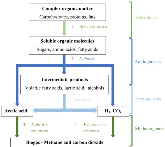
The production of biogas in AD processes is composed by four distinct steps, namely: Hydrolysis, acidogenesis, acetogenesis and methanogenesis (Figure 1.2). During these four steps, biochemical reactions governed by the microbial community in AD reactor takes place.
Hydrolysis
Hydrolysis is the first step of anaerobic digestion process where the polymeric particles are degraded through the action of exo-enzymes, which are secreted by hydrolytic bacteria to produced soluble molecules that can be used by acidogens. Thus carbohydrates, proteins and fats are converted into sugar, amino acids and fatty acids, respectively.2 Despite of this, it is relevant to know that hydrolysis is a relatively slow step due to the slow degradation of certain substances, such as lignin and cellulose, which can limit the rate of the process.19
Acidogenesis
The soluble molecules formed during hydrolysis are further absorbed by acidogenic bacteria that are able to convert them into various organic acids such as propionate and butyrate, as well as H2, CO2 and alcohols.20 Acidogenesis is the most faster step in the anaerobic digestion since acidogenic bacteria has ten to twentyfold higher bacterial growth rates and fivefold higher bacterial yield and conversion rates compared with methanogens.15 Acidogens also tolerate extreme conditions such as high temperature, low pH and high organic loading rate (OLRs).21
Acetogenesis
Acetogenesis is the third step of anaerobic digestion. In this step, the organic acids and alcohols produced through acidogens are converted largely into acetate, as well as, H2 and CO2 by the acetogens and used by the methanogens later.22 In most cases H
2 is not detected due to the relationship between acidogens (H2 producers) and methanogens (H2 consumers), also known as syntrophic interaction. This interaction allows to maintain a low H2 partial pressure.21
Biogas production and purification using membranes processes 4 Figure 1. 2. Stages of anaerobic digestion process and the different bacterial group involved (Adapted from Lier et al. (2008) and Costa et al (2015) 15,18)
Methanogenesis
The fourth and last step of anaerobic digestion is methanogenesis. During this step, hydrogenotrophic and aceticlastic methanogens are the two groups of methanogenic archaea responsibles to produce CH4, CO2, H2 and other residual gases. Hydrogenotrophic methanogens are responsibles to produced CH4 using H2 and CO2, while aceticlastic methanogens convert acetate into CH4.15 The production of CO2 is higher from hydrogenotrophic methanogens (70% of the total CO2 produced) when compared to aceticlastic methanogens (30% of the total CO2 produced).23
1.2.2. Single-Stage anaerobic digestion system
In AD processes for biogas production, a single-stage system is conventionally used where the hydrolysis, acidogenesis, acetogenesis and methanogenesis occur in the same reactor.24,25 The lower capital and operating costs, as well as, low sludge production make this type of process attractive, mainly for bigger plants.26 However, the microorganisms of acidogenesis and methanogenesis have distinct sensitivity to environmental conditions, physiology and growth kinetics.27 Thus, the operational
4. Aceticlastic methanoges 5. Hydrogenotrofic methanoges 3. Acetogens 2. Acidogens 1. Hydrolytic bacteria H2, CO2 Acetic acid Intermediate products
Volatile fatty acids, lactic acid, alcohols
Soluble organic molecules
Sugars, amino acids, fatty acids
Complex organic matter
Carbohydrates, proteins, fats
Methanogenesis
Hydrolysis
Acidogenesis
Acetogenesis
Biogas production and purification using membranes processes 5 conditions are carefully maintained in order to ensure the survival of all microorganisms, namely the methanogens that are more vulnerable than acidogens.
1.2.3. Operational and environmental conditions
In AD several factors, such as reactor configuration, mixing strategy and biomass growth rate, are essencial to achieve a good performance in terms of organic matter conversion and biogas production. Furthermore, it is also essential to controll environmental conditions, such as pH, nutrients content, hydraulic loading rate (HRT) and OLR, in order to allow a good stability since microorganisms, specially methanogens, are very susceptible to environmental changes.22
Reactor configuration
In biogas production process is important to ensure the retention of the biomass sludge in the reactor in order to avoid biomass washout. Therefore, AD can be divided into “low rate” and “high rate” systems and each one is used to treat different wastes depending on their organic loadings. Low rate systems, which are operated with long HRTs, include batch reactor and continuous stirred tank reactor (CSTR) and are generally used to treat slurries and solid wastes. High rate systems use shorter HRTs and are mainly used for wastewater treatment. Examples of this type of system include anaerobic filter, expanded granular sludge bed (EGSB) and Upflow anaerobic sludge blanket (UASB).28
Anaerobic granular biomass
Anaerobic granular biomass possess some very specific properties, such as high sedimentation velocity and high methanogenic activity, which make it very suitable when the process is applied in an UASB (Upflow Anaerobic Sludge Blanket) reactor.29 In these processes granules incorporate microorganisms and are suspended in liquid containing dissolved organic material.22 Therefore the microrganisms are more protected to adverse conditions, such as high salinities.
Temperature
Operating temperature is one of the most significant parameters influencing bioreactors performance.5 Effluent quality, CH
4 yield, effluent quality and enzimes activity are parameters influenced by temperature and abrupt changes may cause disturbance, mainly for methanogens.30
There are two main temperature ranges of operation and different microorganisms operate in each range. Mesophilic microorganisms has an optimum temperature between 30-40°C and thermophilic microorganisms are most productive in the 50-60°C range.31 In thermophilic operations slight variations, as 1 ºC day-1, can lead to process failure.5 In the other hand, under mesophilic operation, changes of about 3 ºC day-1 have no impact in CH
4 production.13 Therefore, bioreactors usually operate in mesophilic temperatures.
Biogas production and purification using membranes processes 6
Salinity
As mentioned above, salinity can effect negatively the biogas production performance since the presence of sodium in effluent inhibites waste biodegradation and in cases where granules are used can lead to their disintegration.32 For these reasons is necessary control the wastewater salinity content in order to promote the adaptation of the microbial community .
pH and redox potencial
The growth rate of methanogens and acidogens are mostly affected by pH and each one has a different optimum pH range. For a single-stage configuration, the reactor is typically maintained between methanogenic limits (neutral pH (6.5 - 7.2)) since methanogenesis is considered a rate-limiting step and methanogens are more sensitive than acidogens to pH changes.30 In these conditions is possible to prevent the predominance of acidogens. The pH can decrease (< 6.0) or increase (> 8.0) due to Volatile Fatty Acids (VFA) accumulation or ammonia accumulation, respectively.13
The redox potential is an important parameter that must be controlled in an anaerobic process. Methanogens need a low redox potential around -300 mV for the optimum performance.22
Organic Loading Rate and Hydraulic Retention Time
Hydraulic retention time (HRT) is one of the most important parameter that affects the reactor operation and needs to be optimized in order to allow a higher degradation of the organic matter. This optimization depends on process conditions and feedstock composition, namely reactor volume (V) and influent flow rate (Q) and can be defined by the equation HRT=V/Q.33
The control of organic loading rate (OLR) is crucial to achieve stability in anaerobic processes and depends of HRT and chemical oxygen demand (COD).34 OLR corresponds to the quantity of organic matter fed per reactor volume per unit time and can be also expressed in terms of COD concentration (KgCOD L-1 d-1). In single stage systems, instability in OLR can negatively affect the balance between acidogenesis and methanogenesis. Acidogens can operate at high loading rates and, consequently, produce high amounts of VFAs that methanogens may not be able to consume due to their slower growth rates which can leads to reactor acidification.35
Nutrients
The nutrients are one of the factors that effects the growth and activity of microorganisms and consequently biogas production. The lack of essential nutrients can also develop problems such as acidification, process instability and low methane yield. Nutrients can be divided in two categories, micronutrients such as calcium and magnesium and macronutrients like nitrogen and phosphorus.36
Biogas production and purification using membranes processes 7
1.3.
Biogas Upgrading
As previously mentioned, the biogas produced through AD processes can be optimized and used as a renewable source of energy. Like natural gas, biogas can be a fuel for a large number of applications. Some of these applications are production of heat and steam, electricity generenation and as a vehicle fuel.30 Depending on the end use, biogas may need to be cleaned and purified before utilization, removing the impurities such as H2S, N2 and NH3 and upgrade decreasing their CO2 content.37 Some applications, such as vehicle fuel and grid injection, require a high energy content in the gas, which is in direct proportion to the CH4 concentration. Through upgrading technologies is possible to remove CO2 and increase the energy content of the gas.38
1.3.1. Technologies for biogas upgrading
Biogas upgrading corresponds to the removal of CO2 from the biogas and consequently the increase of CH4 content which should be more than 95%.13 Therefore to select the upgrading technology it is necessary to take account various factors, such as utilization of biogas, availability resources and investment cost.39 The biogas upgrading will allow to fulfill the requirements of gas appliances (boilers, engines, vehicles, etc) and increase the heating value of the biogas, which leads to a consistent gas quality, similar to natural gas.30
Several biogas upgrading technologies include absorption, Pressure Swing Adsorption (PSA) and membrane separation.38 In any of these technologies it is crucial to keep low methane losses, mainly because CH4 is a greenhouse gas 21 times stronger than CO2.30
1.3.1.1. Absorption
Absorption process is based on the solubility of different gases in a liquid scrubbing solution.37 Usually this process is processed in a column filled with plastic packing allowing to increase the contact between the biogas and the liquid phase.38 In the column, biogas meets a counter flow of liquid and, since carbon dioxide is more soluble than methane, the liquid will leaving the column with high concentrations of CO2, while the gas leaving the column will have an increase of methane concentration. This process presents some advantages such as low methane losses (0.1-1.2 %), high methane recovery (> 99%) and allows solvent recovery through a desorption column.37
There are different absorption technologies and each one use different absorbents: physical, chemical scrubbing and also water scrubing are some exemples of these technologies.38
High pressure water scrubbing (HPWS)
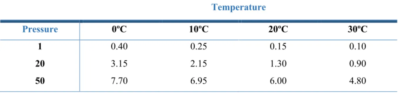
This upgrading technology is the most common used to remove CO2 from biogas. Water scrubbing employs water as a solvent for dissolving CO2 at elevated pressures, since solubility of this gas in water is higher than CH4 (0.035 kg CH4 per kg water at 17 ºC), particularly at lower temperatures
Biogas production and purification using membranes processes 8 as can be seen in Table 1.2.38,40 The effluent water that leaves the scrubber column is saturated with CO2 and can be regenerated using an desorption column and then pumped back to the absorption column. HPWS is an highly efficient process with high methane recovery (> 97%). The main drawbacks of this method are high energy consumption during water regeneration which leads to high operational costs.39
Table 1. 2. Solubility, in kg of CO2 per kg of water at different temperatures (Adapted from Dewil et al. (2008) 30)
Temperature
Pressure 0ºC 10ºC 20ºC 30ºC
1 0.40 0.25 0.15 0.10
20 3.15 2.15 1.30 0.90
50 7.70 6.95 6.00 4.80
Organic physical scrubbing (OPS)
The process of physical scrubbing is similar to water scrubbing, with the difference that the absorvent is an organic solvent, such as polyethylene glycol (PEG), methanol (CH3OH) and N-methyl pyrrolidone (NMP), to absorb CO2.38,39 Comparing to HPWS, this process is more efficient since CO2 shows higher solubilities in these organic solvents than in water. The solvents used can also be regenerated by heating or pressure reduce. Selexol® and Genosorb® are examples of commercially available PEG used in organic physical scrubbing.41 Although it has several advantages such as high methane recovery efficiency (> 97%) and elimination of organic compounds (such as H2S), the OPS operation process when compared to HPWS, requires more energy for the solvent regeneration and high operational costs since the costs of the organic solvents are significantly higher than water.39
Chemical scrubbing process (CSP)
Chemical absorption use amine-based solvents which have high affinity with certain components of a gas mixture.42 Carbon dioxide, in order to be absorbed in the liquid reacts chemically with the amine in the liquid.38 This reaction between the gas and the solvent is reversible, being possible solvent regeneration in a desorption column by heating the liquid using steam. Some of the most commonly used solvents are primary amines such as monoethanolamine (MEA), which is a widely used type of amine for CO2 capture, secondary amines such as diethanolamine (DEA) and tertiary amines such as methyldiethanolamine (MDEA).43 In order to achieve higher absorption capacities, a mixture of MDEA and piperazine (PZ), called as activated MDEA (AMDEA), was developed.39
In CSP methane losses are low (< 0.1%) since the chemical reaction is strongly selective.38 Despite this advantage, the corrosive properties of amines make this process disadvantageous. CSP is
Biogas production and purification using membranes processes 9 also energy intensive, mainly for amine regeneration and some part of the amines degrades or is emitted into the atmosphere, which can harm the environment since amines are toxic.44
1.3.1.2. Pressure Swing adsorption (PSA)
PSA is the most commonly method used in full scale for CO2 separation from CH4 and involves two principal steps, adsorption and desorption.45 This technology uses an adsorbent material, such as zeolites and activated carbon, that selectively adsorb and desorb the undesired gas components by the variation of pressure. This process take place in vertical columns filled by the adsorptive material as a molecular sieve.46 The separation of CO
2 occurs under high pressure (adsorption) and the gas with high affinity to the adsorbent remain sticked whereas the others pass. Desorption column allow solvent regeneration by pressure reduction. Through this method, CH4 recovery rate between 85-90 % can be achieved.47
However,CO2 separation through adsorption method is not considered attractive in large scale since high energy is required for the system, mainly for regeneration and the available adsorbents have low adsorption capacity and selectivity.43 Another fact that can be seen as a disadvantage is the fact that, in PSA, is necessary a primary step of H2S removal since this gas is considered toxic to the process and its adsorption is normally irreversible.39
1.3.1.3. Cryogenic separation
The biogas separation through cryogenic system operates under a very low temperature and high pressure conditions. These upgrading method is based on the principle that various gases liquefy under different temperature and pressure conditions.38 The CO
2 and CH4 boiling points are different, -165.5ºC and -78.2ºC at 1 atm, respectively. Therefore, is possible to separate these two gases by liquefying it. The main disadvantages of this process is the quantity of equipments used that leads to high capital and operational costs and high energy consumption.39
1.3.1.4. Membrane separation
Over the past 40 years, membrane separation processes have gained recognition and become part of current market, being one of the most used methods for landfill gas upgrading.38 Gas separation through membranes consists in using membranes as a selective barrier that transports more easily some gases of the feed mixture than the others due to the different chemical and physical properties of the membrane material and the permeating components (Figure 1.3).39
Biogas production and purification using membranes processes 10 Figure 1. 3. Schematic representation of membrane separation (Adapted from Mulder et al. (2003)48)
This process works at high pressure (20-40 bar) or at low pressure (8-10 bar) being possible to obtain 92-97% methane content.37 There are many advantages of membrane separation in biogas upgrading, where the most important include safety and simplicity of the operation, easy maintenance and operation without hazardous chemicals.49 Furthermore, from the economic point of view, biogas has the perfect composition for the separation to be advantageous through membrane processes, since the volume of gas is relatively low and carbon dioxide content is high.
In order to achieve a viable process, membranes must have a set of characteristics mainly high CO2 permeability and CO2/CH4 selectivity and also chemical and thermal resistance.50 Several type of membranes can be developed in order to achieve specific features and a separation with a high purity of CO2.43 For biogas purification there are three different types of membrane used: polymeric (organic membranes), inorganic or ceramic and mixed matrix membranes (MMMs) which are a combination of polymeric with inorganic fillers.39,51
Polymeric membranes
Nowadays, polymeric membranes are the most used for gas separation. These membranes are made from organic materials, such as polyimide (PI), polysulfone (PSf), cellulose acetate (CA) and polymethyl siloxane (PDMS).39 The use of these membranes for biogas upgrading should always undergo drying prior to membrane separation, since membrane materials are very susceptible to moisture content.51
In dense polymeric membranes, the transport of gases through the membrane is based on solution-diffusion mechanism. According to this mechanism, the permeation of molecules through the membrane is controlled by the relation of two major parameters, diffusivity coefficient and solubility coefficient of the different gases.52 Despite having high mechanical resistance, they possess low thermal and chemical stabilities as well as a trade-off between seletivity and permeability, which means that higher selectivities leads into lower permeabilities and vice-versa.53,54
Biogas production and purification using membranes processes 11
Inorganic membranes
Inorganic membranes are classified as zeolites membranes, ceramic membranes, carbon membranes, metallic membranes or glass membranes, depending on the production material.53 Normally they present a higher thermal and chemical stabilities than polymeric membranes. Furthermore, they present a higher selectivity, specially for carbon molecular sieves and zeolites. On the other hand, some inorganic membranes have some technical difficulties and problems, such as complicated manufacturing procedures, high manufacturing costs as well as low mechanical properties when compared with polymeric membranes.52
Mixed-matrix membranes (MMMs)
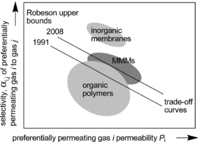
Mixed-matrix membranes (MMMs) were developed as an alternative to polymeric and inorganic membranes, combining the advantages and overcome the problems of each. These membranes consist of an inorganic filler (dispersed phase) incorporated into a polymeric matrix (continuous phase).53 The use of these two materials provides the possibility to the membranes to posses the high mechanical resistance and easy processability of polymeric membranes and the high separation performances of inorganic membranes, which results in a membrane with high separation performace with a potencial to overcome the trade-off for gas separation (Figure 1.4).53,55
Figure 1. 4. Schematic representation of the relationship between selectivity and permeability with the Robeson upper bound.53
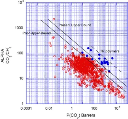
The correlation between permeability and selectivity was demonstrated first in 1991 by Robeson with an upper limit, through the analysis of various references about membrane gas separation studies and later updated in 2008. Therefore was possible to discover the relationship between permeability and selectivity that can be graphically represented as upper bound by the log of the separation factor as a function of the log of the higher permeable gas. The Robeson upper bound of 1991 was valid for a variety of gas pairs, including CO2/CH4 (Figure 1.5).54 However, the update performed in 2008 allow to introduce another gas pairs.56 The successful of MMMs preparation depends on the properties of
Biogas production and purification using membranes processes 12 polymer and inorganic filler used that affect membrane morphology and separations performance. If the affinity between the polymer and the inorganic filler is low, it can result in the formation of voids at the polymer-filler interface.53 Usually, polymers with highly selective properties lead to better separation performances.
Thus, glassy polymers with a high selectivity are preferred comparing to high permeable rubbery polymers with low selectivity.57 To choose the inorganic fillers is necessary to considere some properties, mainly their surface and chemical structure as well as particle size distribuition. There are two types of inorganic fillers, porous and non-porous. Porous inorganic fillers are the most used, since they possess high permeability and low selectivity than non-porous. Examples of porous inorganic fillers are zeolites, silica and carbon molecular sieves.58 As mentioned above, the polymer-filler interactions need to be strong but these materials have shown low compatibilities towards the polymer matrix.
These aspects may be crucial to discover new materials to help answer some of these challenges with high affinity to the polymer matrix, such as metal-organic frameworks (MOFs).59
Figure 1. 5. Upper bound correlation between CO2 and CH4.54
Ionic liquids (ILs)
In the last decade, ILs have gained interest as new functional materials to promote more efficient processes. They can be used in different applications, such as solvents for biological molecules, batteries and fuel cell or carbon dioxide capture processes.
ILs are salts composed of an organic cation and an organic or inorganic anion, which have a melting point lower than 100ºC instead of traditional salts that melts at much higher temperatures.60 The
Biogas production and purification using membranes processes 13 low melting point of ILs can be explained by the low intermolecular interactions, low aggregation of their asymmetrical ions and also their charges dislocation.61,62 These materials have another interesting preperties, such as high thermal and chemical stability, low flammability and low volatility. However, the main characteristic that make them very promising materials is the possibility to enhance their physical and chemical preperties only by changing the cation and anion in their structure. Thus, ionic liquids have been finding an increasing number of applications as “green” solvents. Examples of these applications are organic and chemical chemistry, energy, biotechnology separation processes.60,62,63 Nowadays, the use of ILs in separation processes is one of the most active areas of reaserch due to the reasons refered above but also because the good levels of solubility and selectivity of CO2 in these solvents when compared with other gases. For the last one, some studies have been done for the CO2 solubility in ILs where was concluded that the anion has a dominant role in CO2 solubility.63
Polymeric ionic liquids (PILs) and PIL/IL composite membranes
As referred above, ILs can be applied in a large number of applications. The use of ILs for functional polymers development allowed the appearance of polymeric ionic liquids (PIL)s.
Polymeric ionic liquids, also known as poly(ionic liquid)s or PILs, is a new class of polyelectrolites that results from the introduction of the functional groups associated to ILs into functional polymers. PILs combine the thermal stability and high CO2 selectivity of ionic liquids (ILs), with the common properties of polymers. Contrary to classic polyelectrolites that are soluble in water, most PILs are only soluble in polar organic solvents.60 Despite these advantages of using PILs, the low gas permeability and diffusivity through the polymer matrix achieved, led to the development of high performance CO2 separation membranes and different strategies have been explored using different membrane arragements, such as polymer/IL composite membranes, supported ionic liquid membranes, ion gel membranes and PIL-IL composite membranes.64
In PIL/IL composite membranes, the ILs are incorporated into PILs matrix. The development of PIL/IL membranes is an attractive strategy to obtain membranes that combine the best functionalities of both materials, which allow to obtain membranes with enhanced CO2 transport properties.65 In order to achieved the maximum CO2 separation is necessary to take into account the compatibility of both materials. Recently, the incorporation of nanofillers, such as MOFs, has gained interest to improve the CO2 separation performance of PIL-IL membranes.
Metal-organic frameworks (MOFs)
In the past two decades, MOFs have emerged as a new class of crystalline porous materials and as a potencial fillers in the polymer matrix.55 Their structure is composed of inorganic metal ions (or metal clusters) connected by means of ligands forming a three-dimentional structure.66
Biogas production and purification using membranes processes 14 MOFs have gained interest as inorganic fillers for MMMs due to their unique characteristics. In addition to their reasonable thermal and mechanical stabilities, the structure of these materials can be adapted to the desired application in terms of pore size and surface area, being possible to enhance their affinity towards different gases.59,67 In several studies is referred that these materials also reveal capacity for CO2 removal due to their adsorption selectivities and capacity to CO2 capture. These properties allow MOFs to have a high potencial where compared to the conventionally used microporous inorganic material such as zeolites.68 Generally, MOFs has higher porosity and surface area than zeolites, activated carbons and silica gel.66 Therefore, the challenge in using MOFs in MMMs is to choose the appropriate polymer/MOF combinations for a specific separation.
1.4.
Objectives of this thesis
The main objective of this thesis was the development and characterization of new mixed matrix membranes with metal organic frameworks, polymeric ionic liquids and free ionic liquids for the purification of biogas produced from a co-digestion system using an anaerobic co-digestion process.
The first part of this thesis consisted on biogas production through the operation of a single-stage anaerobic system at laboratorial scale treating a mixture of tannery and leachate, increasing the salinity overtime. The increase of salinity can affect negatively the reactor performance, being necessary to control this parameter. Therefore, it is important to study the adaptation of microbial culture to different salinities.
The second part of this work was to prepare and study two groups of new membranes to remove CO2 from a biogas stream. In the first group, PIL-IL membranes using two different PILs, Poly[pyr11][Tf2N] and Poly[pyr11][C(CN)3], four ILs, [C2MIM][Tf2N], [C2MIM][C(CN)3], [C2MIM][BETi] and [C4MIM][PF6] and three different solvents, acetone, acetonitrile and DMF, was prepared. In the second group, two MMMs were prepared, namely Poly[pyr11][C(CN)3]/40 [C2mim][C(CN)3] and Poly[pyr11][Tf2N]/40 [C2mim][BETi], with the the metal organic framework (MOF-5).
The membranes prepared were studied to evaluate if the incorporation of MOFs enhanced the membrane properties as well as the CO2/CH4 ideal selectivity and CO2 permeability when compared with the membranes composed only by the PIL-IL.
All membranes were characterized by different methods, namely scanning electron microscopy (SEM) to evaluate their morphology, fourier transform infrared spectroscopy (FTIR) to evaluate ILs and MOF incorporation in PIL, thermogravimetric analysis (TGA) to evaluate their thermal stability, contact angle to determine their hydrophilicity, mechanical properties to evaluate their resistance and flexibility and gas permeation experiments with pure gases (CO2 and CH4) at 30ºC.
Biogas production and purification using membranes processes 15
2.
Materials and methods
2.1.
Operation of a single-stage anaerobic digestion system
2.1.1. Materials
2.1.1.1. Substrate and inoculum
Leachate and tannery, used as substrates in this study, were provided by Koto, Slovenia. The wastes were previously characterized (see results section) and stored in a refrigerator at 4°C until needed to prepare the influent. The influent was prepared one time per week diluting the tannery with leachate in order to achieve the salinity required (5, 10 or 15 g Na+ L-1).
The upflow anaerobic sludge bed (UASB) reactor was inoculated with anaerobic granular sludge (30% of working volume) collected from a Biobed Expanded Granular Sludge Blanket (EGSB) reactor treating non saline brewery wastewater (Portugal).
2.1.1.2. Experimental Setup and operation
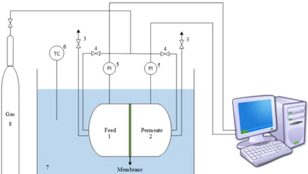
A single-stage AD system was operated during 61 days in continuous mode at lab-scale with 2.2 L of working volume. The overall system configuration of the UASB reactor is represented in Figure
2.1.
Figure 2. 1. Schematic representation of the single-stage anaerobic system: (1) Influent container; (2) UASB reactor; (3) Gas-liquid-solid separator; (4) pH/redox measure flask ; (5) KOH solution bottle; (6) Biogas container; (7) Clarified fermentation
Biogas production and purification using membranes processes 16 broth container; (8) Redox controller; (9) pH controller; (10) Gas flow meter; (11) peristaltic pump. Components not shown: water bath system.
The reactor was maintained at 30°C (mesophilic conditions) using a water bath system (CW-05G, Lab. Companion, Jeio Tech, Korea). The pH was automatically controlled 7.07 ± 0.09 by the automatic addition of potassium hydroxide (KOH) 5M. The upflow velocity was maintained at 2 m h-1 with a peristaltic pump (Watson-Marlow 323E/D) and the biogas production was measure through a flow meter (Bioprocess Control, Sweden).
Table 2. 1. Operational conditions used in the reactor. Leachate (%) Tanney (%) Sodium concentration (g Na+L-1) Time (d) pH HRT (d) OLR (gCODsoluble L-1d-1) 91 9 5 0-5 7 5 2.2 ± 0.3 6-18 7 3 2.6 ± 1.0 83 17 10 19-42 7 3 3.7 ± 0.1 74 26 15 43-61 7 3 3.7 ± 0.1
The reactor startup conditions were pH of 7.00, redox of -178 mV, HRT of 5 days and OLR of 2.2 ± 0.3 g COD L-1 d-1. After the initial acclimatization to the salinity, the HRT was changed to 3 days (maintaining the salinity) in order to increase the amount of wastewater treated and, consequently, the biogas production.
The conditions imposed on the reactor are presented in Table 2.1. The reactor was subjected at three different salinities (5, 10 and 15 g Na+ L-1), obtained through different ratios of leachate:tannery and corresponding to an OLR between 2.2 ± 0.3 and 3.7 ± 0.1 g COD L-1 d-1.
2.1.2. Analytical methods
In order to assess reactor stability, standard control parameters were monitored including the quantification of COD, proteins, total suspended solids (TSS) and volatile suspended solids (VSS), nutrients, organic acids (OA) and ions. Sampling (feed and reactor) was performed three times per week and centrifuged at 11.000 rpm during 3 minutes (Micro star 17, VWR, USA). The resulted supernatant was stored at -20ºC until further analysis. To determine TSS and VSS, samples were taken one time per week. In order to control the granular sludge, TSS and VSS samples were taken at various heights (H0, H1 and H2).
Chemical Oxygen Demand
COD is an indirect measurement that allows quantifying the amount of organic matter present in the sample. Through the colorimetric method, COD concentration was measured using Hach Lange kits
Biogas production and purification using membranes processes 17 of the concentration range 0-1000 g L-1 O
2. Previously, for soluble COD (SCOD) analysis the samples were pre-treated filtration with a 0.2 µm syringe filter and diluted according to the kit range. Contrarily to soluble COD analysis, the samples for total COD (TCOD) were not filtered. Samples were digested (Hach Lange HT 200S) at 148°C for 120 minutes. Lastly, after cooling at room temperature, COD concentration was measured using a spectrophometer (Hach Lange DR 2800).
Proteins
The protein content was determined according to a modified Lowry Protein Assay method.69 This colorimetric method is one of the most used to measure the concentration of proteins present in the sample and is based on two main reactions, one is the reaction of protein with copper under alkaline conditions and the other one is the reduction of the phosphomolybdic-phosphotungstic reagent by the copper-treated protein. The reagents used are described in Table 2.2. The protein content was determined in feed samples and reactor samples, previously centrifuged, filtered with a 0.2 µm syringe filter and diluted with milli-Q water. Briefly, 1.5 mL of solution C was added to 500 μL of the diluted samples, mixed in the vortex and incubated in the dark for 10 minutes at room temperature. After that, 150 μL of solution D was added, mixed in the vortex and incubated in the dark for 30 minutes at room temperature. Absorbance was measured at λ=750 nm (Hach Lange DR 2800 spectrophotometer) and total protein concentration was calculated through a standard calibration curve of bovine serum albumin (BSA 98%, pH 7.0, Sigma Aldrich) (0 - 100 mg L-1).
Table 2. 2. Reagents used in protein protocol.
Reagents Composition
Solution A 10g Na2CO3 + 0,1g C4H4KNaO6.4H2O + 500 mL NaOH 0,1M
Solution B 0,5g CuSO4.5H2O + 1drop H2SO4 + 100 mL H2O
Solution C Solution A + Solution B in a proportion of 50:1
Solution D Folin 50% (v/v)
Total suspended solids (TSS) and volatile suspended solids (VSS)
Total and volatile suspendend solids concentrations (TSS and VSS) were determined for influents and reactor broth once a week and in duplicate according to standard methods70. Firstly, the glass fibre filters (VWR, Glass fibre filters 21 mm) were weighed. After this each well-mixed samples was filtered in a vacuum pump (VARIAN - Filtration System), placed in aluminium dishes and dried up overnight at 105°C (Oven TR 60, Nabertherm, Soquimica). The weight of dried sample corresponded to the concentration of TSS. The dried sample was then reduced to ash throughout ignition in a oven (Nabertherm, Soquimica) for 2 hours at 550 °C. VSS concentration was achieved by the difference between the weight of the sample before and after the step at 550 °C.
Biogas production and purification using membranes processes 18
Nutrients
The concentration of nutrients (NH3-N and PO4-P) were obtained by a colorimetry method implemented in a continuous flow analyser (Skalar San ++, Skalar Analytical, Netherlands) with a standard calibration curve of ammonium chloride (NH4Cl 99%, Sigma) and ortho-phosphoric acid (H3PO4 85%, Panreac) at concentrations ranging from 4 to 20 mg L-1. The samples were previously centrifuged (Micro star 17, VWR, USA) and diluted with milli-Q water.
Organic acids analysis by High performance liquid chromatography (HPLC)
Organic acids (acetic, butyric, isobutyric, propionic, valeric and isovaleric acids) were quantified through high performance liquid chromatography (HPLC) using a Biorad Aminex HPX-87H column (300 x 7.8 mm) and a Biorad pre-column (125-0129 30 x 4.6 mm) coupled to an IR detector. The analysis was conducted at 30 °C with sulphuric acid (H2SO4 0.01 N) as eluent at a 0.5 mL min-1 flow rate. The concentrations of organic acids were calculated through a standard calibration curve (31 - 1000 mg L-1 of each organic acid). Sample preparation included the filtration using a syringe filter (0.2 μm pore size filter).
Gas analysis (GC)
In order to analysis the composition of the biogas produced, in terms of CH4, CO2, O2, N2 and H2 content, was used gas chromatography (GC). The GC (Angilent Technologies 7890B) was equipped with a TCD detector and 50 meters of CP-Molsieve 5A and 25 meters PoraBOND Q columns. The mobile phase was argon with 5 mL min-1 of flow rate. The temperatures of the injection port and the detector were 120 and 70ºC, respectively. Gas samples were collected in a syringe (100 µL) and injected as soon as possible into the equipment.
Ions
The sodium concentration was analysed by inductively coupled plasma-atomic emission spectrometry (ICP-AES). The ICP-AES Horiba Jobin-Yvon Ultima is equiped with a 1.00 m Czerny-Turner monochromator, a RF generator at 40.68 MHz.
The determination of chlorine concentration was performed by DIONEX (ICS3000). The system was composed by a IR-detector, a pre-column (Ionpac AG9-HC) and a column (Ionpac AS9-HC) at 25 °C. The eluent was NaCO3 (9 mM) with a flow rate of 1 mL min-1 using a standard concentration range of 10-100 mg L-1.
2.1.3. Parameters calculation
To assess the reactor performance, some parameters were calculated. The removal of organic matter was calculated using Equation 1, that relates the soluble COD in the substrate (feed) and in the reactor:
Biogas production and purification using membranes processes 19
𝐶𝑂𝐷$%&'()*=[𝑆𝐶𝑂𝐷]/%%0− [𝑆𝐶𝑂𝐷]$%)23'$
[𝑆𝐶𝑂𝐷]/%%0 × 100 (Equation 1)
To determine the CH4 produtivity were used the Equation 2 that takes into account the percentage of CH4 in the produced biogas, the biogas flow rate and the reactor volume. CH4 yield calculation (Equation 4) depends on the same parameters as productivity but also HRT and the difference between de VFA in the feed and in the reactor (∆𝑉𝐹𝐴), calculated using Equation 3.
𝐶𝐻> 𝑝𝑟𝑜𝑑𝑢𝑡𝑖𝑣𝑖𝑡𝑦 = %𝐶𝐻> 100 × 𝑄KLM 𝑉$%)23'$ , in L 𝐶𝐻> 𝐿 ST 𝑑ST (Equation 2) ∆𝑉𝐹𝐴 = 𝑉𝐹𝐴/%%0− 𝑉𝐹𝐴$%)23'$, 𝑖𝑛 𝑔 𝐶𝑂𝐷 𝐿ST (Equation 3) 𝐶𝐻> 𝑦𝑖𝑒𝑙𝑑 = %𝐶𝐻> 100 × 𝑄Y)Z ∆𝑉𝐹𝐴 × 𝑉$%)23'$× 𝐻𝑅𝑇, 𝑖𝑛 L 𝐶𝐻> 𝑔K]^ST (Equation 4)
Biogas production and purification using membranes processes 20
2.2.
Biogas upgrading using MMMs with MOFs
2.2.1. Materials
Mixed matrix membranes (MMMs) were prepared using two different polymeric ionic liquids (PIL)- poly(diallylmethylammonium)bis(trifluoromethylsulfonyl) imide, PIL Tf2N and PIL C(CN)3, four ionic liquids, namely,1-ethyl-3-methylimidazolium bis(trifluoromethylsulfonyl)imide ([C2MIM][Tf2N], 1-ethyl-3-methylimidazolium tricyanomethanide ([C2MIM][C(CN)3]), 1-ethyl-3-methylimidazolium bis (pentafluoroethylsulfonyl) imide ([C2MIM][BETi]) and 1-butyl-3-methylimidazolium hexafluorophosphate ([C4MIM][PF6]) and the metal-organic framework (MOF-5). Properties of the ILs used were determined and are shown in Table 2.3.
Acetone, acetonitrile and N,N dimethylformamide (DMF) were used as solvents.
Table 2. 3. Properties results of the ionic liquids used.
The PILs used contain the same polycation, pyrrolidinium ([pyr11]) and two different counter-anions, [Tf2N] and [C(CN)3]. These PILs were synthesized by an anion exchange reaction using the commercially available polymers lithium bis(trifluoromethylsulfonyl)imide (99 %) and sodium tricyanomethanide (98 %) following an established procedure71, obtaining a white solid, PIL Tf
2N and PIL C(CN)3, respectively. The polymers were then whashed with milli-Q water and dried at 60ºC until a constant weight was achieved.
Methane (CH4) (Praxair, USA) with 99.5% of purity and carbon dioxide (CO2) (Praxair, USA) with 99.998% of purity were used in gas permeation tests.
MOF-5
MOF-5, also known as IRMOF-1 is the most studied MOF with promising industrialization results. The structure of MOF-5 is composed of Zn4O as metal clusters connected by 1.4 – benzenedicaboxylate (BDC) as linear linkers.72 The main characteristics of MOF-5 are high thermostability (up to 400 ºC), high porosity and high adsorption capacity for CO2. Several zinc-based MOF possess high specific surface area, tunable pore size and large accessible pore volume, which make them ideal adsorbents.73,74 This MOF also belongs to a class of nanoporous coordination polymers
Ionic Liquid wt % of water Molecular weight (g.mol-1) Density(g.cm3) 30ºC Viscosity (mPa.s) 30ºC [C2MIM][Tf2N] 0.19 391.31 1.517 26.172 [C2MIM][C(CN)3] 0.50 229.28 1.030 11.468 [C2MIM][BETi] 0.31 491.32 1.590 55.951 [C4MIM][PF6] 2.20 284.18 1.356 72.725
Biogas production and purification using membranes processes 21 (IRMOFs) characterized by interchangeable organic likers, allowing manipulation of pore size and surface area through the specific ligand selection.75
Figure 2. 2. Structure of MOF-5. 76
2.2.2. Methods
2.2.2.1. MOF-5 synthesis and characterization
For the synthesis of MOF-5, 2.2 g of zinc nitrate hexahydrate, Zn(NO3)2.6H2O
(Sigma-Aldrich,USA, purity 99.99%), was mixed with 0.92 g of terephthalic acid, H2BDC (Sigma-Aldrich, USA, purity 98%) in 100 mL of N,N-Dimethylformamide, DMF (Carlo Erba, France, purity 99.8%) and 2.7 ml of distilled water. The solution obtained was stirred for a sufficient time until complete dissolution and then transferred to an Teflon autoclave and introduced into a high temperature oven (modelo) for 48 hours at 120°C. After cooling at room temperature, the crystals were washed with DMF and dried for 12 hours at 150°C in the oven obtaining about 0.446 g of MOF-5.
In Table 2.4 are identified the characteristics and the structure of MOF-5.
Table 2. 4. Chemical and physical properties of MOF-5
MOF Molecular
formula
BET Surface area (m2/g)
Pore size
(nm) Particle size (µm)
MOF-5 Zn4O(C8H4O4)3 3000 77 0.8 77 1-2 78
Powder X-Ray Diffraction
Powder X-Ray diffraction or PXRD is a commom technique that allows the measurement of diffraction pattern of crystalline materials being possible to verify its composition, purity and structure. In the scope of this thesis, PXRD data were collected to confirm the crystalline structure of MOF-5. Said spectrum was obtained using a MiniFlex II bentchtop diffractometer (Rigaku Corporation,
Japan) with CuKa radiation operating at 30 kV and 15 mA and the measuremens for the MOF-5 were carried out between 2º and 70º (2q) with a step of 0.02º according to Ming et al. 2014.79