iii
Yevhen Doloshytskyy
Licenciado em Ciências de Engenharia Mecânica
Electro-Optical/Infrared sensor turret integration
on an aircraft - structural impact on LOCKHEED
MARTIN C-130H and design methodology
Dissertação para obtenção do Grau de Mestre em
Engenharia Mecânica
Orientador: João Mário Burguete Botelho Cardoso, Professor Auxiliar, Faculdade de
Ciências e Tecnologia - Universidade Nova de Lisboa
Co-orientador:
João Rui Franco Duarte, Engenheiro de Projeto Estrutural, OGMA -
Ind-ústria Aeronáutica de Portugal. S.A
Júri:
Presidente: Prof. Doutor Daniel Cardoso Vaz
Arguente: Mestre Rui Manuel Roma de Jesus
. Pereira
Vogal: Prof. Doutor João Mário Burguete .
Electro-Optical/Infrared sensor turret integration on an aircraft - structural
im-pact on LOCKHEED MARTIN C-130H and design methodology
Copyright © Yevhen Doloshytskyy, Faculdade de Ciências e Tecnologia, Universidade Nova de Lisboa.
Dissertação apresentada à Faculdade de Ciências e Tecnologia da Universidade Nova de Lisboa para a obtenção do grau de Mestre em Engenharia Mecânica
Setembro 2015
Electro-Optical/Infrared sensor turret integration on an
air-craft - structural impact on LOCKHEED MARTIN C-130H
Acknowledgments
The development of this thesis was possible due to support of many people to whom I extent my gratitude:
To Eng .João Rui Duarte, for his support and comprehension.
To Professor João Cardoso for his guidance and support during the project.
To Professor António Mourão, for making this project possible.
To Delfim Costa for his companionship and support during the last years.
To my friends for all the comprehension and support.
And most importantly to my family, to whom I owe everything.
Abstract
The growing need to patrol and survey large maritime and terrestrial areas increased the need to integrate external sensors on aircraft in order to accomplish those patrols at increasingly higher altitudes, longer range and not depending upon vehicle type.
The main focus of this work is to elaborate a practical, simple, effective and efficient methodology for the aircraft modification procedure resulting from the integration of an Elec-tro-Optical/Infra-Red (EO/IR) turret through a support structure. The importance of the devel-opment of a good methodology relies on the correct management of project variables as time, available resources and project complexity. The key is to deliver a proper tool for a project de-sign team that will be used to create a solution that fulfils all technical, non-technical and certi-fication requirements present in this field of transportation. The created methodology is inde-pendent of two main inputs: sensor model and aircraft model definition, and therefore it is in-tended to deliver the results for different projects besides the one that was presented in this work as a case study. This particular case study presents the development of a structure support for FLIR STAR SAPHIRE III turret integration on the front lower fuselage bulkhead (radome) of the LOCKHEED MARTIN C-130 H. Development of the case study focuses on the study of local structural analysis through the use of Finite Element Method (FEM).
Development of this Dissertation resulted in a cooperation between Faculty of Science and Technology - Universidade Nova de Lisboa and the company OGMA - Indústria Aeronáutica de Portugal
Resumo
A crescente necessidade de reconhecimento e vigilância de grandes áreas terrestres e marítimas implicou o desenvolvimento da integração de sensores EO/IR exteriores em aerona-ves de forma a efetuar o patrulhamento a altitudes cada vez mais altas, de maior alcance e atra-vés de vários tipos de veículos.
O grande foco deste trabalho passa pela elaboração de uma metodologia de um projeto de modificações de uma aeronave prática, simples, clara, eficiente e eficaz resultante do estudo da integração de uma torreta de um sensor Electro-Ótico/Infravermelho. A correta definição de uma metodologia é de grande importância de forma a obter uma correta gestão das variáveis de projeto como o tempo, alocação de recursos e a complexidade do projeto. O objetivo centra-se em desenvolver uma ferramenta útil para uma equipa de projeto de forma a obter uma solução final que cumpre requisitos técnicos, não técnicos e requisitos de certificação, presente neste tipo de indústria. A metodologia desenvolvida é independente tanto do modelo do sensor a ins-talar como a aeronave a ser modificada, de forma a poder ser empregue em projetos diferentes do caso presente neste trabalho. O caso de estudo apresenta (através do uso da metodologia) o desenvolvimento de uma estrutura de suporte para a torreta do sensor FLIR STAR SAPHIRE III. Esta estrutura é especificamente desenvolvida para a aeronave LOCKHEED MARTIN C-130 H. O desenvolvimento do caso de estudo é focado na análise estrutural através da análise de elementos finitos.
O desenvolvimento desta Dissertação resulta da cooperação entre a Faculdade de Ciên-cias e Tecnologia - Universidade Nova de Lisboa e a empresa OGMA - Indústria Aeronáutica de Portugal, S.A
List of Contents
1 INTRODUCTION ... 1
1.1 OBJECTIVES AND STRUCTURE ...1
1.2 MOTIVATION ...4
2 INSIGHT OF EO/IR SENSORS ... 9
3 MODIFICATION DESIGN PROCEDURE... 13
4 FEASIBILITY ANALYSIS OF TURRET INTEGRATION ON DIFFERENT AIRCRAFT LOCATIONS ... 23
4.1 AIRCRAFT CHARACTERISTICS AND LOCATIONS ... 23
4.2 SELECTION CRITERIA AND RESPECTIVE TIERS OF SIGNIFICANCE ... 24
4.3 CRITERIA INTERDEPENDENCE ... 26
4.4 LOCATION VIABILITY ANALYSIS ... 27
4.5 LOCATION VIABILITY CONCLUSIONS ... 29
5 STATE OF THE ART: AIRFRAME AND STRUCTURAL MODIFICATION. ... 31
5.1 HISTORICAL BACKGROUND AND BASIC PRINCIPLES ... 31
5.2 FINITE ELEMENT METHOD ... 33
5.3 AIRFRAME BREAKDOWN ... 37
5.4 AIRCRAFT STRUCTURE MATERIALS ... 39
5.5 AIRCRAFT LOADS ... 39
5.6 STRUCTURAL ANALYSIS ... 42
5.6.1 Static analysis ... 42
5.6.2 Buckling and Crippling ... 43
5.7 WEIGHT AND BALANCE ... 45
6 CASE STUDY: FLIR STAR SAPHIRE III INTEGRATION ON LOCKHEED MARTIN C-130H FRONT BULKHEAD ... 49
6.1 PURPOSE OF CHANGE ... 49
6.2 REQUIREMENTS ... 49
6.2.1 Certification Requirements ... 49
6.3 FAILURE CRITERIA ... 51
6.3.1 Material yield strength ... 51
6.3.2 Buckling ... 52
6.3.3 Crippling ... 52
6.4 MODELLING ... 53
6.4.1 Material Properties ... 53
6.4.2 Bulkhead beam Sections ... 53
6.4.3 Web ... 56
6.4.4 Geometric simplifications ... 56
6.4.5 Modelling and Meshing Validation ... 56
6.4.6 Structure Development ... 62
6.5 STRUCTURAL LOADS AND BOUNDARY CONDITIONS ... 66
6.5.1 Structural Loads ... 66
6.5.2 Boundary Conditions ... 68
6.6 POST-PROCESS AND BEAM SECTION CHARACTERIZATION. ... 69
6.6.1 VMES, Buckling and Crippling Considerations ... 69
6.6.2 Ultimate load conditions ... 69
6.6.3 Limit load conditions ... 74
6.6.4 Structural Part Strength Result ... 77
6.6.5 Structural Part Deformation Result ... 78
6.6.6 Other miscellaneous results ... 79
6.7 WEIGHT AND BALANCE ... 79
6.7.1 Weight impact ... 79
6.7.2 Balance verification ... 81
7 METHODOLOGY DEFINITION ... 83
8 CONCLUSION ... 91
8.1 CONCLUDING REMARKS ... 91
8.2 MAIN CONCERNS AND FUTURE CONSIDERATIONS ... 92
9 BIBLIOGRAPHY ... 95
APPENDIX A ... 99
E01-H/E02-H ... 105
E03-H ... 109
E04-H ... 112
List of Figures
FIG.1-1IRON TRIANGLE ADAPTATION[2]. ... 1
FIG.1-2LOCKHEEDMARTINC-130 MAIN CHARACTERISTICS[4] ... 3
FIG.1-3FRAMEWORK OF THE PROJECT DEVELOPMENT FOCUS... 3
FIG.1-4EASA-REGULATION ... 5
FIG.1-5MAIN MILESTONES DURING THE DEVELOPMENT OF A MODIFICATION DESIGN... 6
FIG.2-1-IMAGE CAPTURED BY EO SENSOR OF THE L-3WESCAMMX-15HDI[7] ... 10
FIG.2-2IMAGE CAPTURED BY U.S.NAVY LOCKHEED P-3ORION DURING SEARCH & RESCUE MISSION ... 11
FIG.2-3-EXAMPLE OF A EO/IR SENSOR TURRET [9] ... 11
FIG.3-1-MODIFICATION DESIGN OVERVIEW OF THE TURRET MODIFICATION PROJECT. ... 13
FIG.3-2-MODIFICATION DESIGN DIVIDED IN SEVERAL DOMAINS ... 14
FIG.3-3-DIFFERENCE BETWEEN INTERACTION AMONG DIFFERENT DOMAINS IN AXIOMATIC DESIGN AND THE PROJECT IN STUDY ... 15
FIG.3-4INTERACTION BETWEEN FUNCTIONAL,CERTIFICATION AND PHYSICAL DOMAINS ... 19
FIG.3-5FIRST APPROACH TO THE METHODOLOGY OF PRELIMINAR ANALYSIS ... 21
FIG.4-1LOCKHEEDMARTINC-130H DURING LANDING [4]. ... 23
FIG.4-2TURRET INTEGRATION COORDINATES IDENTIFICATION ... 30
FIG.5-1-COMPARISON BOARD OF THE ANALYSIS METHODS INVOLVING PROJECT COMPLEXITY. ... 32
FIG.5-2-LOCKHEEDMARTINC-130 WITH THE RADOME REMOVED. ... 33
FIG.5-31D MODEL (A);2D MODEL (B);3D MODEL (C) OF A I SECTION TYPE BEAM [29] ... 35
FIG.5-4ILLUSTRATION OF DIFFERENT SUB ASSEMBLIES IN AN AIRCRAFT. ... 38
FIG.5-5REPRESENTATION OF LINEAR AND NONLINEAR ANALYSIS RELATION [36]. ... 42
FIG.5-6COLUMN END-FIXITY CONDITIONS [40] ... 44
FIG.5-7EXAMPLE OF BUCKLING (LEFT) AND CRIPPLING (RIGHT) PHENOMENA OF I-SECTION BEAM ... 45
FIG.5-8CRIPPLING STRESS (FCC) OF ALUMINIUM EXTRUSION ALLOYS [39] ... 45
FIG.5-9WEIGHT AND BALANCE VERIFICATION PROCEDURE ... 47
FIG.6-1-BULKHEAD PARTS BREAKDOWN ... 54
FIG.6-2-WEATHER ANTENNA PARTS BREAKDOWN ... 55
FIG.6-3-CAD MODELLING OF THE C-130H FRONT FUSELAGE BULKHEAD (LEFT); DE-ICING AND ANTI -ICING TUBING (RIGHT) ... 56
FIG.6-4MODELLING SIMPLIFICATION INTO FEA SOFTWARE ... 57
FIG.6-5SOLUTION APPROXIMATION ERROR IN ORDER TO ELEMENT NUMBER IN 1D ELEMENTS TYPE ... 58
FIG.6-6REPRESENTATION OF THE SELECTED 1D ELEMENT FOR MESHING VALIDATION ... 59
FIG.6-8EVOLUTION OF TENSILE PROPAGATION DUE TO DECREASE OF ELEMENT SIZE [ M] ... 60
FIG.6-9SOLUTION APPROXIMATION ERROR IN ORDER TO ELEMENT NUMBER IN 2D ELEMENTS TYPE ... 61
FIG.6-10EVIDENCE OF POINT OF SINGULARITY IN MESH VALIDATION ANALYSIS. ... 62
FIG.6-11EXAMPLE OF BEAM188 CROSS SECTION MESH ... 62
FIG.6-12GENERAL DIMENSIONS OF THE SUPPORT STRUCTURE [M] ... 63
FIG.6-13SUPPORT STRUCTURE BREAKDOWN ... 64
FIG.6-14SUPPORT STRUCTURE RADOME FITTING ... 64
FIG.6-15CHANNEL-TYPE EXTRUDED BEAM CHARACTERIZATION (LEFT) AND L-TYPE EXTRUDED BEAM CHARACTERIZATION (RIGHT). ... 64
FIG.6-16REPRESENTATION OF FORCE APPLICATION LOCATIONS AND RESPECTIVE FORCES (RIGHT) AND THEIR GEOMETRIC CHARACTERISTICS (LEFT). ... 68
FIG.6-17MAIN LONGITUNAL SUPPORT BEAMS OF LOWER FRONT FUSELAGE. ... 69
FIG.6-18STRESS DISTRIBUTION OF E01-H/E02-H IN LOAD CASE 1 ... 70
FIG.6-19STRESS DISTRIBUTION OF E03-H IN LOAD CASE 1 ... 71
FIG.6-20STRESS DISTRIBUTION OF E04-H IN LOAD CASE 1 ... 71
FIG.6-21STRESS DISTRIBUTION OF E05-Q/E06-Q IN LOAD CASE 1 ... 72
FIG.6-22STRESS DISTRIBUTION OF E07-V/E08-V IN LOAD CASE 5 ... 73
FIG.6-23-WEB STRESS DISTRIBUTION DURING ULTIMATE CONDITIONS. ... 73
FIG.6-24KEY STRUCTURAL ELEMENT CONNECTIONS ... 74
FIG.6-25SHEAR FLOW DISTRIBUTION ALONG L-BEAM SECTION... 75
FIG.6-26FINAL SOLUTION CRITICAL TENSILE ZONE... 77
FIG.6-27REPRESENTATION OF THE MOST CRITICAL DEFORMATION WHICH IS VERIFIED IN YZ ... 78
FIG.6-28AIRCRAFT BALANCE REFERENCE SYSTEM ... 79
FIG.6-29CENTER OF GRAVITY LIMITATIONS ... 82
List of Tables
TABLE 2-1TYPES OF IR SENSORS... 10TABLE 2-2COMPARION TABLE OF DIFFERENT EO/IR MODELS HIGHLIGHTING THE CHOSEN FOR THIS PROJECT. ... 12
TABLE 4-1DSM OF SELECTION CRITERIA FOR OPTIMUM LOCATION ANALYSIS ... 27
TABLE 4-2LOCATION VIABILITY RATING SYSTEM. ... 27
TABLE 4-3VIABILITY COMPARISON BOARD OF VARIOUS LOCATIONS ON THE CONSIDERED AIRCRAFT MODEL. ... 29
TABLE 5-3TYPES OF QUASI-STATIC LOADS APPLIED ON AN AIRCRAFT ... 40
TABLE 5-4TYPES OF DYNAMIC LOADS APPLIED ON AN AIRCRAFT ... 41
TABLE 6-1SUGGESTION OF THE CERTIFICATION COMPLIANCE MATRIX ... 50
TABLE 6-2SELECTED MATERIAL PROPERTIES ... 53
TABLE 6-3BEAM AND BEAM SECTION IDENTIFICATION OF THE BULKHEAD ... 54
TABLE 6-4BEAM AND BEAM SECTION IDENTIFICATION OF THE WEATHER RADAR SUPPORT ... 55
TABLE 6-5PROPERTIES OF WEB PANEL. ... 56
TABLE 6-6WEATHER RADAR CHARACTERIZATION ... 57
TABLE 6-7 RELATION BETWEEN ELEMENT SIZE AND RELATIVE ERROR IN 1D ELEMENT ... 58
TABLE 6-8RELATION BETWEEN ELEMENT SIZE AND RELATIVE ERROR IN 2D ELEMENT ... 61
TABLE 6-9CHANNEL BEAM AVAILABLE ON STRUCTURAL REPAIR MANUAL ... 65
TABLE 6-10L-TYPE BEAM AVAILABLE ON STRUCTURAL REPAIR MANUAL ... 65
TABLE 6-11LIMIT CONDITIONS LOAD CASES APPLIED ... 67
TABLE 6-12ULTIMATE CONDITIONS LOAD CASES APPLIED ... 68
TABLE 6-13APPLIED FORCES ON FIXATION POINTS ... 68
TABLE 6-14CHOSEN PARTNO FOR THE E01-H/E02-H COMPOSITION ... 70
TABLE 6-15CHOSEN PARTNO FOR THE E03-H COMPOSITION ... 70
TABLE 6-16CHOSEN PARTNO FOR THE E04-H COMPOSITION ... 71
TABLE 6-17CHOSEN PARTNO FOR THE E05-Q/E06-Q COMPOSITION ... 72
TABLE 6-18CHOSEN PARTNO FOR THE E017-V/E08-V COMPOSITION ... 73
TABLE 6-19LIMIT LOAD CASE 5 FOR E09-H/E10-H/E11-H/E12-H ... 74
TABLE 6-20COMPARISON RATIO OF L-BEAM TYPE BEAM CANDIDATES... 76
TABLE 6-21STRESS, RESUME OF FEM RESULT FOR EACH ULTIMATE CONDITION LOAD CASE ... 77
TABLE 6-22MODAL ANALYSIS RESULTS ... 79
TABLE 6-23AIRCAFT CG MODIFICATION DUE TO TUEER INTEGRATION ... 80
6-24LIST OF REMOVED ITEM FROM AIRCRAFT MODIFICATION ... 80
TABLE 6-25LIST OF INSTALLED ITEMS IN AIRCRAFT MODIFICATION ... 80
TABLE 6-26AIRCRAFT MODIFICATION OVERALL IMPACT ... 81
TABLE 6-27IMPACT OF OPERATIONAL, PAYLOAD AND FUEL WEIGHT ON AIRCRAFT ... 81
TABLE 9-1GEOMETRIC CONSIDERATIONS AND BUCKLING TENSION OF CHANNEL SECTIONS FOR E01-H/E02-H ... 105
TABLE 9-2GEOMETRIC CONSIDERATIONS AND MAXIMUM CRIPPLING STRESS ... 105
TABLE 9-3LOAD CASE 1-E01-H/E02-H ... 106
TABLE 9-4LOAD CASE 2-E01-H/E02-H ... 106
TABLE 9-5LOAD CASE 3-E01-H/E02-H ... 107
TABLE 9-6LOAD CASE 4-E01-H/E02-H ... 107
TABLE 9-7LOAD CASE 5-E01-H/E02-H ... 108
TABLE 9-10LOAD CASE 1-E03-H ... 109 TABLE 9-11LOAD CASE 2-E03-H ... 110 TABLE 9-12LOAD CASE 3-E03-H ... 110 TABLE 9-13LOAD CASE 4-E03-H ... 111 TABLE 9-14LOAD CASE 5-E03-H ... 111 TABLE 9-15LOAD CASE 6-E03-H ... 112 TABLE 9-16LOAD CASE 1-E04-H ... 112 TABLE 9-17LOAD CASE 2-E04-H ... 113 TABLE 9-18LOAD CASE 3-E04-H ... 113 TABLE 9-19LOAD CASE 4-E04-H ... 114 TABLE 9-20LOAD CASE 5-E04-H ... 114 TABLE 9-21LOAD CASE 6-E04-H ... 115 TABLE 9-22GEOMETRIC CONSIDERATIONS AND BUCKLING TENSION OF CHANNEL SECTIONS FOR
Acronims and nomeclature
AC - Air Conditioning
APF - Aerodynamic Pressure Force
APU - Auxiliar Power Unit
b/t = ratio between width (b) and thickness (t) of a C-channel section.
BEW - Basic Empty Weight
BEM - Basic Empty Moment
c = End fixity coefficient
CCM - Certification Compliance Matrix
CG - Center of Gravity
= CG position with respect to MAC length
CS - Certification Specification
CVE - Compliance Verification Engineer.
DAF - Dynamic Amplification Factor
DOA - Design Organization Approval.
DOF - Degree of Freedom
DSM - Design Structural Matrix
E = Modulus of Elasticity
EASA - European Aviation Safety Agency
EMC - Electromagnetic compatibility
EMA - Experimental Modal Analysis
EO - Electro-optical
Fcc - Critical crippling Stress
FEA - Finite Element Analysis
FEM - Finite Element Method
G - Universal gravitational constant
I - Moment of Inertia
IR - Infrared
IPB - Internal Parts Breakdown
k = Number of stress evels considered in the analysis
L = Effective length
LEMAC - Leading Edge of Mean Aerodynamic Chord arm
MAC - Mean Aerodynamic Chord
MLW - Maximum Landing Weight
MTOW - Maximum Take-off Weight.
MOC - Mean Of Compliance
MS - Margin of Safety
MZFW - Maximum Zero Fuel Weight
NA - Neutral Axis
NHAA - Negative high angle of attack
= Number of loading cycles at stress level
NLAA - Negative low a [1]ngle of attack
OEW - Operating Empty Weight
= Critical Buckling Load
PHAA - Positive high angle of attack
PLAA - Positive low angle of attack
= First moment of inertia along x
equivalent stress
= Normal stress in plane 1 and in direction 1
= Shear stress in plane 2 and direction 3
t = thickness
TC - Type Certificate
STC - Supplemental Type Certificate
VMES - Von Mises Equivalent Stress
= Shear Stress
= Shearing deformation
= Natural Frequency
1
Introduction
1.1 Objectives and structure
In the following development of this Master Thesis, the underlying purpose is to develop a methodology for the integration of a Electro-Optical (EO) and Infrared (IR) sensor turret in a military type aircraft. This project is related to the branch of aeronautics and its elaboration re-sults from a cooperation between the Faculty of Science and Technology - Universidade Nova de Lisboa and OGMA - Indústria Aeronáutica de Portugal, S.A.
Integration of EO/IR sensor turret on an aircraft presents three major areas of study: structural impact, aerodynamic impact and system integration impact. This project is focused on the structural impact of sensor turret integration. Following a brief analysis of what is an EO/IR sensor, a complete methodology is developed in order to elaborate a Preliminary Design of a structural solution for integration of sensors of this nature on an aircraft. Nerveless, this work is conducted simultaneously with aerodynamic impact study byCosta [1], whose results will be considered further in this work.
Developing a methodology for a project design is often related to the perfect balance be-tween cost, deadline and scope of work. The calibration and establishment of each aspect di-rectly influences the two major factors that will define a project, expected quality result and the resources available with the time and cost invested in this project. Thus, usually a project design team must define the expected result, trying to achieve it with all of the relative factors.
Carrying out this work, this thesis is divided in several sequential milestones distributed along 8 chapters:
EO/IR sensors breakdown (Chapter 2)
Modification design overview (Chapter 3)
Feasibility analysis of turret installation on a military aircraft (Chapter 4)
State of the art of theoretic assumptions during the modification project analysis (Chapter 5)
Modification requirements settlement for the project - case study (Chapter 6)
Project design process - case study (Chapter 6)
Structure analysis of the final solution -case study (Chapter 6)
Turret integration methodology definition (Chapter 7)
Final remarks and conclusions about the future work to be done (Chapter 8)
Among the presented sensors in Chapter 2 that resulted from a market study survey, the sensor to be studied and that is considered in this project is the one that is most common among the installations in these type of aircraft model. The vehicle type to be studied is airborne, thus, the aircraft model to be considered is LOCKHEED MARTIN C-130 H (general characteristics on Fig. 1-2). C-130 is itself a compound of numerous variants. The "H" variant was chosen for this subject due to its popularity and its great abundance in this market. Due to the fact that Por-tuguese Air Force has 3 C-130H and 3 C130H-30 [3] (extended modification of "H" variant nicknamed as Super-Hercules) in its fleet 3, is probably also one of decisive factors to engage the "H" variant.
This chapter will focus only on the preliminary design of FLIR STAR SAPHIRE III sup-port structure in the front bulkhead of the considered aircraft model. Concluding the chapter, the consideration of the EO/IR sensor model can be varied but the technical specification of the air-craft model makes it somehow difficult to adapt to other vehicle of the same nature. However, the methodology that is developed is to be adapted and considered for similar aircraft models. During the project design process, it is intended to create a support structure that connects the aircraft and the EO/IR sensor turret support plate, as defined in Fig. 1-3
Being concluded the Case Study, comes the time to define the output of this project in Chapter 7, Methodology definition. The focus of this methodology is gathered in detailing the Preliminary design of the project, and defining the needed procedure at each step. Finally, Chapter 8 will held the main project conclusions and suggestions for further work. Concluding, the final objectives of this project are:
To develop an universal feasibility analysis of EO/IR sensor turret installation location for any aircraft model;
To develop a support structure for integration of FLIR STAR SAPHIRE III on LOCKHEED MARTIN C-130 H;
Fig. 1-2 LOCKHEED MARTIN C-130 main characteristics[4]
To develop a practical, simple and effective methodology that can deliver a pre-view of the structural impact analysis and the development of a support structure for the EO/IR turret in an aircraft.
1.2 Motivation
During the last three decades, the rising demand to fulfil some of the needs of civil and military entities led to the growing and development of the external sensor technology. Nowa-days, this external sensor market is wide enough to offer the right solution in accordance with the mission purpose and the vehicle type (land, airborne or maritime) in which these sensors are mounted. The process of integrating one of these sensors on an airborne vehicle is a joint ven-ture between technical certification and design project.
Certification reveals to be a fundamental milestone in airborne transportation in order to guarantee the compliance of numerous safety and environmental requirements worldwide. In aviation, safety depends greatly on 3 factors [5]: men (pilots, maintenance mechanics, air traffic controllers and other personnel that is involved in this industry), the environment (external fac-tors that can, or cannot, influence the flight conditions), and the machine (understood as the air-craft in which the flight is performed, its operational status and airworthiness). Operational status of an aircraft is understood as the quality of its operational behaviour, as airworthiness is possession of the necessary requirements for flying in safe conditions, within allowable limits (clear definition found in Italian RAI-ENAC Technical Regulations).
In accordance with Regulation Committee (CE) 748/2012, OGMA is a Design Organiza-tion Approval (DOA) entity. A DOA entity is authorized to perform maintenance and modifi-cation in Large Aircrafts (Certifimodifi-cation Specifimodifi-cation 25) and Light Aircrafts (Certifimodifi-cation Specification 23). These maintenance and modification are authorized in avionic installations; electrical systems, structures and interiors, among others.
Acceptable Means of Compliance and Guidance Material - Part 21 is relative to airwor-thiness, in which occurs the certification of all design and maintenance projects. Part 21 is the branch of certification which is the focus of this study, more specifically sub part B,D,E and M (Type Certification; Changes; Repairs).
The procedure of an aircraft modification approval depends largely from its modification type: Minor or Major. It is considered that a modification is Minor if: it has a negligible effect on aircrafts mass or its Centre of Gravity (CG); no modification to the original airframe is re-quired (not considering possible local reinforcements). Otherwise, the modification is rated as Major. A DOA entity is normally authorized to design and approve a Minor modification to be made. In case of a Major modification, however, a DOA entity is required to apply for a Sup-plemental Type Certificate (STC). In order to understand the nature of an STC document, one must first understand the meaning of a Type Certificate (TC):
TC - Issued by the regulator (EASA). An aircraft model which is allowed in European airspace has a document which states that the aircraft was manufac-tured according to a design which complies with airworthiness requirements. This document contains information about the aircraft performance category, maximum weight limits, engine models, minimum crew, requirements of the Cer-tification State; maximum passengers and other operating limitations.
STC - Issued by the regulator (EASA). Document which states the approval of a Major modification in compliance with airworthiness and what are the changes to the operating limitations present in the original TC document of an aircraft model. TC also holds any new certification requirements to be met or reviewed after this modification.
From a preliminary analysis to other similar or not aircraft modification projects, it is suggested that the modification is rated Major. It is important to highlight the word "suggestion" once the definition of the modification type can only be done by an experienced member of the Design Team.
This work embraces a modification of an aircraft with Maximum Take Off Weight (MTOW) of about 79 380 kg. Thus, this project will be referred to the certification of Large Aircrafts (CS-25) which is related to any aircraft which MTOW > 5670 kg. Certification of an aircraft in this field requires the accomplishment of numerous Certification Requirements (CS) through study of various static (strength and structural stress) and dynamic (fatigue and damage tolerance) analysis. In the planning of an aircraft modification design project, one must follow a structure of well defined procedures adopted by an DOA entity.
Preliminary design, which is the core focus of this project, relies in creating a solution for the turret support structure, its analysis and justification of several CS and non-CS requirements defined for the modification. This work relies in justification of these requirements by static
The study of all the described phenomena will be done recurring to an Finite Element Analysis (FEA) software. FEA is an analysis method approximation to a complex problem, with a complex geometric domain by dividing this domain into finite number of simpler sub do-mains, called finite elements. Further, the analysis of each element and their respective interre-lation is understood based on theoretic assumptions and governing equations depending on the type of analysis and on FEA software in use. FEA reveals to be suited for far more complex problems then analytic approximation and not as costly as experimental analysis. In accordance with the necessary project design procedures of the support structure, all justification and calcu-lation is approached from a conservative way, in order to guarantee a satisfactory safety factor.
2
Insight of EO/IR sensors
In this chapter, a robust approach is proposed on electro-optical (EO) and infrared sensors (IR), their fundamentals and their respective market use. A sensor is defined as an object that detects signals and information of the surrounding environment. The EO and IR capabilities of a sensor settle the spectral band, namely the interval of different types of information which the sensor receives. For the purpose of this particular study, these sensors are part of airborne ob-servation systems. Depending on the application, several sensor types can be integrated in a tur-ret that is fixed to the aircraft, which is the case. Target phenomenology often dominates the choice of spectral band of use by the sensor, but not entirely. The band choice is also influenced by vagaries of atmospheric transmission and scattering [6].
EO/IR systems are greatly dependent on either target reflection by outer radiation (solar, moonlight or artificial) or the radiation of the target itself. Namely, a majority of EO/IR systems do not apply radiation directly at a target (using a standard video-camera with an integrated flashlight in dark environment can be taken as an example). Therefore, these systems are called passive [6].
On the contrary, IR sensors group is defined by equipments which capture the radiation that is emitted by a certain target. These sensors generally operate on a waveband between 0.7-14 m. This is understood as a wide interval in which there is a number of different sub-classes of IR sensors [1]. Fig. 2-12 is an example of an image captured by an IR sensor. The image was captured by an U.S. Navy Lockheed P-3 Orion during search and rescue mission of an Egyptian ferry Al Salam Baccaccio in 1998. At the rear of the ferry, the visible white dots are the crew and passengers to be rescued.[8]
IR sensor class Operation Waveband [ m]
Near-Infrared (NIR) 0.7-1.1
Shortwave-Infrared (SWIR) 1.1-3
Midwave-Infrared (MWIR) 3-5
Longwave-Infrared 8-14
Nowadays, most of EO/IR sensors on the market are fit do adapt to either ground, mari-time or airborne vehicles. Particularizing the case, once integrated on an aircraft these sensors can provide a wide range of applications. Intelligence, Surveillance and Reconnaissance (ISR); border-coastal patrol; and ground force protection are the most common missions of these sys-tems in military purpose activities. A EO/IR sensor is divided into different subparts like Opera-tor Console and Turret, this last one particularly important for the purpose of this study. The
Fig. 2-1 - Image captured by EO sensor of the L-3 WESCAM MX-15HDI [7]
which integration on the aircraft is the output expected in this dissertation. An example of a EO/IR turret is shown on Fig. 2-3.
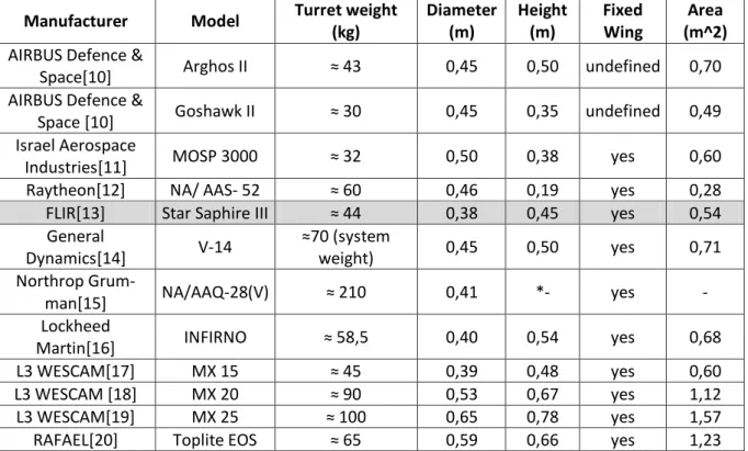
Currently, the market supply of EO/IR turret is surprisingly wide with more than 15 man-ufacturers found, including LOCKHEED MARTIN, L-3 WESCAM, FLIR, and others. From the research on the available products in the category of EO/IR turrets, a comparison is made be-tween the models and their main characteristics. At this point, urges the issue of defining what are truly important characteristics of a EO/IR sensor turret for the purpose of this study.
Consulting various available turret data-sheets on the market, specifications like sensor capability, resolution and zoom ratio were outward to the importance of this project. Thus, the important characteristics to be taken into consideration are general dimensions, geometry and weight of each turret model. Table 2-2 presents the main considered models, their relevant
char-Fig. 2-2 Image captured by U.S. Navy LOCKHEED MARTIN P-3 Orion during search & rescue mission
acteristics and a brief comparison. Verifying the already existing EO/IR sensor integrations for this aircraft model, one specific model came up as the most utilized, FLIR STAR SAPHIRE III.
Manufacturer Model Turret weight (kg) Diameter (m) Height (m) Fixed Wing Area (m^2)
AIRBUS Defence &
Space[10] Arghos II ≈ 43 0,45 0,50 undefined 0,70
AIRBUS Defence &
Space [10] Goshawk II ≈ 30 0,45 0,35 undefined 0,49
Israel Aerospace
Industries[11] MOSP 3000 ≈ 32 0,50 0,38 yes 0,60
Raytheon[12] NA/ AAS- 52 ≈ 60 0,46 0,19 yes 0,28
FLIR[13] Star Saphire III ≈ 44 0,38 0,45 yes 0,54
General
Dynamics[14] V-14
≈70 (system
weight) 0,45 0,50 yes 0,71
Northrop
Grum-man[15] NA/AAQ-28(V) ≈ 210 0,41 *- yes -
Lockheed
Martin[16] INFIRNO ≈ 58,5 0,40 0,54 yes 0,68
L3 WESCAM[17] MX 15 ≈ 45 0,39 0,48 yes 0,60
L3 WESCAM [18] MX 20 ≈ 90 0,53 0,67 yes 1,12
L3 WESCAM[19] MX 25 ≈ 100 0,65 0,78 yes 1,57
RAFAEL[20] Toplite EOS ≈ 65 0,59 0,66 yes 1,23
In all of the presented information about FLIR STAR SAPHIRE III[13], it is important to highlight that the equipment is qualified for MIL-STD-810 and MIL-STD-461. MIL is a United States Military Standard for equipment certification. Further contractual, design and qualifica-tion procedure should be in compliance with certificaqualifica-tions presented above.
MIL-STD-810 - equipment verified to be able to sustain the limit conditions which it will experience during service life (environmental stress, possible equipment defects, among others);
MIL-STD-461 - electromagnetic compatibility (EMC) in either energy reception or propagation. EMC settles the possibility of various equipments within a small perimeter whose functionality can occur in parallel without unwanted effects.
3
Modification Design Procedure
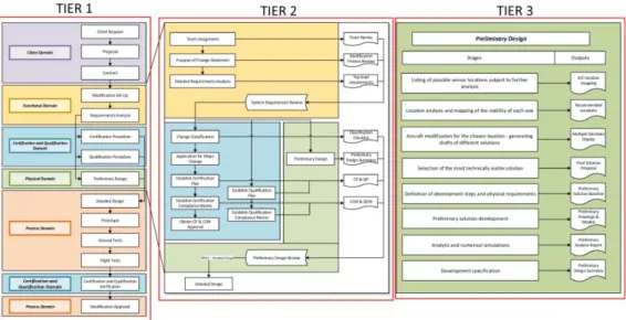
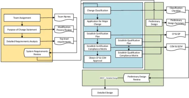
Normally, a DOA entity has a developed Modification Design plan which it follows in case of a modification project for a civilian aircraft. A Modification Design plan document is usually a flowchart or a compound of flowcharts with well established guidelines in accordance with the regulator procedures. The modification project in this particular study is not of a civil-ian type, but military. In cases of a military type modification, there are no defined procedures with a regulator to be followed. Normally, a DOA entity has the regulator privileges to proceed in its will in this type of modification. Taking as an example, in a military and state aircraft modification project, change approval and change modification can be done entirely by a DOA entity. It is up to the client to accept or to not accept the modification procedures to be made. However, a military type modification can be conducted in accordance with a civilian type pro-cedure which is commonly accepted by a given client. Thus, the DOA entity Modification De-sign plan based on civilian type modification is particularized for this project. During this chap-ter, this particularization is explained in three tiers of detail, which can be observed in Fig. 3-1, where this tiers are divided in columns. The focus of this study will set on Preliminary Design and its development, but before exploring it, an understanding of the whole process is needed.
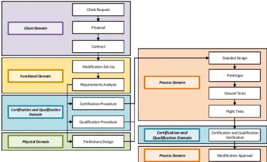
Beginning with the top level tier of detail, usually a modification project is di-vided into several steps of procedure which are often sequential, as shown on Fig. 3-2. These steps are referred as domains, each one of them being characteristics of certain type of procedure. The act of evoking the "domain" characterization is intended to re-call the Axiomatic Design theory for a better understanding and segregation of the Modification Design plan. Axiomatic Design is a systems design methodology that uses matrix methods to systematically analyse the transformation of customer needs in func-tional requirements, design parameters, and process variables[21]. Axiomatic Design is particularly useful for this type of projects because it allows to define simply what is needed (Costumer Domain), what it needs to do (Functional Domain), how it is suppose to look (Physical Domain) and how to create it (Process Domain). The left side of Fig. 3-2 shows an example of interaction between different domains in common Axiomatic Design project. After a brief observation it is clear that the normal process follows a se-quential order. However, the same is not applied on this particular project, as can be ob-served on the right side of the same Fig. 3-3. During the Preliminary Design phase, there is a number of decisions to be made during the process elaboration that recur to the Functional Domain. Thus, during the Preliminary Design is witnessed a constant in-teraction between these two domains, Functional and Physical.
The nature of this particular project and this particular field of engineering requires the consideration of an extra domain, regarding Certification and Qualification process which isn't referred in Axiomatic Design methodology. The steps that are part of this domain occur in a parallel time significance with the physical domain.
Naturally, a certain domain represents a set of tasks regarding to a specific nature. Fol-lowing is explained each domain principles:
Client Domain
First contact with the client is established with the purpose to determine the costumer overall needs (in this particular case, a turret) and to settle the contractual agreement.
Client Request - beginning with initial meetings; defining future negotiation dates (meet-ing schedule) and fundamental objectives of the modification project. Definition by the client of the aircraft model to be customized. If the client does not has yet a specific turret model to be installed, one will be suggested by the design team.
Proposal - negotiation about the first outline of the project to the client, its general steps and the raw order price (modification project minimum and the maximum budget limits).
Contract - purpose of making the project official. A scope of work is defined to establish main milestones and the predicted overall project time.
Functional Domain
What does turret has to perform? It's main functionalities, requirements and main cau-tions to take in account.
Modification Set-Up - The modification process begins with a project team assignment. The custom procedures involve the verification of previous projects of this nature made on the aircraft model. A minute must be elaborated about a detailed reason, description of change, and the main concerns to be accounted.
Requirements Analysis - estimating the needed requirements for the outcome project. Those requirements are of various natures as contractual, regulatory, functional, operational and performance requirements which the modifications interferes with.
Certification and Qualification Domain
The aviation sector contains a strict procedure regarding to modifications, taking in ac-count various types of procedure in accordance of a present situation followed by the monitor-ing of the regulator.
Certification procedure - Preparation of the change certification procedure. Activities are established in order to demonstrate the compliance with the Certification Specification in accor-dance to aircraft's airworthiness and other safety parameters. Appropriate means of compliance are set to justify the involved requirements.
Qualification Procedure - This section bounds to classify and certify client requirements other than relative to airworthiness. Taking as an example a client requirement of a specific exterior airplane painting or relative.
Certification and Qualification Validation Verification - An assurance of the certification is made. Follows the action of confirming if the certification status still complies with the estab-lished certification.
As can be observed, there is a recurrence to the Certification and Qualification Domain during the procedure of the Process Domain, specifically between the Flight Tests and the Modification Approval. That once more implies the not so sequential behaviour of this project.
Physical Domain
First steps toward solution development. At this point, most of the decisive steps are to be made with the interaction of Functional Domain as is seen forward.
Process Domain
Comes the detailed development, decisive tests and the needed specification for the modification action.
Detailed Design - Begins the creation of the necessary documentation in order to actually perform the modification. The following documentation includes models and installation draw-ings, material, product and process specifications. The necessary procedures and reports are also developed in this step.
Prototype - Materialising the solution. A procedure is made for the prototype to be sub-ject for the future tests.
Ground Tests - Performing the required ground tests (if applicable).
Flight Tests - Performing the required flight tests (if applicable).
Modification Approval - Follows the final steps of modification procedure. A final ap-proval of the client is expected. All the needed operational, maintenance and regulation docu-mentation are presented to the involved entities in the project.
From the descriptions that were made above about the different domain contained in the Modification Plan, it may not be clear to acknowledge the complexity and the scope of each step. The time length of this thesis cannot cover in detail all the domains, and so, it is necessary to focus on a particular area of the Modification Project. Thus, this study will cover in detail the Preliminary Design, part of Physical Domain. Nevertheless, to completely understand the Pre-liminary Domain, it is yet necessary to understand and explore the Functional, Physical, Certi-fication and QualiCerti-fication domains.
The Fig. 3-4, is a close-up of Fig. 3-1, highlighting the Functional (yellow), Physical (green) and Certification and Qualification (blue) domains showing some of compound steps. This figure contains the second tier of detail of Fig. 3-1 and as shown, some of these steps result in an output documentation. The whole of outputs from a domain can result in an important milestone. This milestone sets if the objectives of the process during this domain are achieved, resulting in the fact that all of the requirements are met to proceed to the next step. Beginning with the more detailed view of procedure in the following domains:
Functional Domain
Purpose of Change Statement - a creation of an abstract to justify, state the main reasons and proceeding the modification to be made.
Detailed Requirements Analysis - the action of gathering the different types of require-ments to be met in this project. At this point, the list of requirerequire-ments that is the output in this step are not definitive and the future meeting with the client may establish new requirements.
System Requirements Review - marked as the milestone of the Functional Domain. This may not be necessary in some projects where the initial requirements are well established on the Detailed Requirements Analysis. This milestone concerns such topics as qualification and client requirements.
Certification and Qualification Domain
Change Classification - in a civilian type modification, a checklist (referred by the regu-lator) is completed in order to verify that the modification is Major. (significant/non-significant/substantial). As referred before, in case of a military type modification, the change classification and approval can be done entirely by an DOA entity.
Application for Major Change - In cases of a civil type modification, the checklist filled in the previous step is presented to the regulator. In case of a military or state type modification, this step is not necessary. Follows the filling of the EASA form FO.TCHH.0031
Establish Certification Plan - The Change description is defined; Certification Basis, Pro-gram Schedule and respective responsibilities. Certification Basis is a sub-document which de-fined the Certification Specification (CS) to be evaluated in this modification (CS-25 in this par-ticular case), among other types of protection requirements. The complexity of the specific modification may involve the collaboration of a Type Certificate Holder (which is usually the regulator). The result of this step is the Certification Plan document, which may be updated along the process.
Establish Certification Compliance Matrix (CCM) - Once the CS document is defined (in this case CS-25) comes the time to define specifically the requirements applicable to this modi-fication and the respective means of compliance. Means of compliance are a set of 8 types of justification of a requirement. The different MC (Means of Compliance) are the following[22]:
MC0 - Compliance Statement: rationalization and allusion based on previous and/or existing similar modifications on the market.
MC2 - Calculation/Analysis: implication of use of structural, fatigue and other types of analysis.
MC3 - Safety Assessment: associating methods like Fault Tree Analysis (deductive procedure used to determine the various combinations of hardware, software and human failures that could cause undesired consequences [23]) among other failure predicting methods.
MC5/MC6 - Ground Tests/Flight Test: Functional tests performed on the ground/air with possible electromagnetic interference tests to be performed.
MC7 - Inspection by Specialist: only performed by a Compliance Verification En-gineer in case of a mandatory visual confirmation of the modification quality result.
MC9 - Equipment Qualification: common certification of used equipment on the given modification by the recognition of one of 3 document types: Technical Standard Order (TSO), European Technical Standard Order (ETSO) and Parts Manufacturer Ap-proval (PMA).
Means of Compliance 4 (Laboratory Tests) and 8 (Simulation) are not considered in this project as they are not currently used by the DOA entity.
Physical Domain
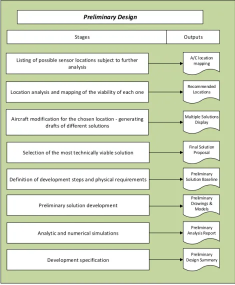
Preliminary Design - Specified steps in Fig. 3-5.
Preliminary Design Review - Documentation of the final support structure. At this point, the developed solution has already fulfilled the requirements stated in CCM and ready for further test procedure and production development specification.
As referred, Fig. 3-4shows the interaction between Functional, Certification and Qualification and Physical domains, being this last two interconnected in a parallel set in order to generate the expected outputs. As an example of this kind of interaction, the CCM is one of the most important documents for this particular study. It will expose the most critical requirements to be verified (consulting CS 25 Am. 16) and how can they be justified (M.O.C). As verified in the following chapters, once the resulting CCM is set-tled, the requirements that can be justified by MC 2 will be subject to the validation.
Preliminary Design
Listing of possible sensor locations subject to further analysis
Location analysis and mapping of the viability of each one
Aircraft modification for the chosen location - generating drafts of different solutions
Selection of the most technically viable solution
Definition of development steps and physical requirements
Analytic and numerical simulations
Development specification
A/C location mapping
Recommended Locations
Multiple Solutions Display
Final Solution Proposal
Preliminary Solution Baseline
Preliminary Drawings & Models
Preliminary Analysis Report
Preliminary Design Summary
Stages Outputs
Preliminary solution development
4
Feasibility analysis of turret integration
on different aircraft locations
4.1 Aircraft characteristics and locations
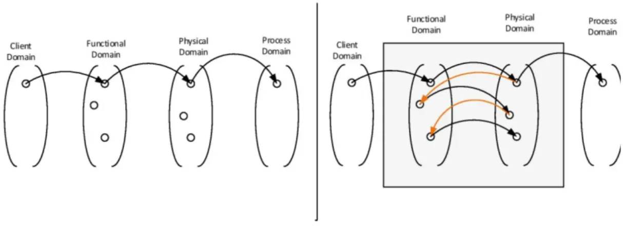
With a length of 29.78 m, height of 11,65 m and a wingspread of 40,41 m [24], the four-engine turboprop C-130H is a part of the C-130 family which is one of most popular cargo and ground support aircrafts in the military sector to this day, servicing more than 65 operators worldwide [4]. On the Fig. 4-1, a U.S. Air Force C-130H is shown.
At preliminary analysis, the aircraft itself gives the impression of a great availability and liberty in choosing a location to integrate the system. However, the process itself reveals to be far more complex. Consulting several maintenance manuals, structural repair manuals and a IPB of the aircraft, the integration of the sensor turret reveals itself dependent on several criteria, varying the viability of these in accordance with a given area of the airplane. Thus, the solution lies in dividing the aircraft's body in 17 areas and analyze each area individually and inde-pendently. Following, a representation of the respective segmentation can be consulted in [Ap-pendix A].
4.2 Selection criteria and respective tiers of significance
In the process of selection of the optimal location on the aircraft to install a sensor turret, urges the need to create a selection and validation process in order to apply this method in any airplane model and any sensor turret model, regarding only to their respective characteristics. During the selection of the necessary and sufficient criteria, it is necessary obtain a result where all the criteria selected are in fact independent of one another and in case they are not, what is their magnitude of importance and interrelation. The final criteria which should be considered for the selection of the optimal location are the following:
1. Sensor´s sight range - It was determined as one of the major criterion for the system. From an operational point of view, it is mandatory that the sensor oper-ates within its total range of sight capabilities.
2. Interference with other parts - This criterion includes every kind of interfer-ence that may occur. It was considered to be high priority since one must analyse:
Antennas (distance);
Vibrations induced on other parts;
Influence in airflow;
Contact with other components;
Internal geometry (structural interferences);
3. Possible damage to the sensor - Possible damage to the sensor implies a short-age to the device´s longevity, which creates the need for regular maintenance. Implies that the modification lose its purpose in a client´s point of view. 4. Pressurized areas of the aircraft - Delimitates the implementation in
pressur-ized areas by the need of an additional external structure in these areas. Prefer-ence given to the non pressurized areas of the aircraft by the simplicity of integra-tion.
5. Sensor's Characteristics:
A - Aerodynamic impact - can be responsible for certain change in the per-formance characteristics of the aircraft. Although it is not a mandatory factor, in can rule out some options.
6. Structure´s integrity - in a first approach to the issue, one must consider the fra-gility of the aircraft's local structure since it gives an approximate idea of how difficult the modification is.
7. Modification complexity - criterion that regards to the eventual cost and size of the whole process of the modification. It is a gathering of the most important is-sues taken in the consideration for the choice of the location.
Once the essential criteria are defined, it is important to analyse how each of this criteria will affect the decision, in what way, and if there is an consideration priority of their usage. As an example, should the criterion 7 be studied before criterion 1? Is criterion 6 deterrent in con-sidering some locations as viable? The first issue to consider is the magnitude of importance of each criterion in a relative scale of comparison. Thus, these 8 criteria are divided in 3 groups with different importance value on the selection process.
The first group and the most important, is a whole of criteria that are critical to the proc-ess. By these means, this criteria preclude any type of consideration if one of them is violated. Penurious sight range in a certain location, for example, is a clear indicator that the sensor can-not be considered on installation in that particular area, otherwise, the purpose of its installation is corrupted. Thus, the criterion 1 is constituent of the first group of importance. This aircraft´s model in study, as well as any other existing models, has a complex structure with numerous external and internal components. Some of these components are of extreme importance. Their relocation or considering a respective contact or proximity to the turret can be prohibitive, thus it is important to verify and assure that the installation of the turret in a specific location does not interfere with the correct functioning of other components vital to the aircraft's operability. So, the criterion 2 is also to be considered in the first group of importance. The last criterion to be considered for this group of the higher importance is the possible damage that a turret may suffer in being located in certain areas of the aircraft. Limiting turret´s life cycle is not a viable option by placing it in a location that can induce a high probability in collision with rocks or a vibration that causes severe fatigue to the turret's structure, taking these factors example.
become deteriorative to aircraft´s operation stability and performance in either aerodynamic or structural way due to sensor's specifications. Thus, this criterion must be taken in account with a due importance.
Looking at the not yet considered criteria, 6 and 7, urges the need to interpret their impor-tance. An aircraft´s structural integrity is not linear. It can be greater in some areas then in other due to the local stresses or applied forces. Thus, combining the possibility of a turret installation with the structural integrity factor results in a decision of how to proceed to the next step and the needed requirements. Not being decisive or restraining, this criterion hampers some deci-sions to be made. Last but not least, the criterion 7 can be understood as an aggregation of all the decisions made in other criterions considered previously. This criterion is without any doubt, the least important factor to be considered in this selection process. Below, is presented the summary of the division in 3 respective tiers of importance:
Tier 1 - Criteria that preclude the location's viability:
1 - Sensor's sight range;
2 - Interference with other parts;
3 - Possible damage to the sensor;
Tier 2 - Criteria that restrain the location´s viability:
4 - Pressurized area of the aircraft;
5A - Sensor's characteristics - aerodynamic impact;
5B - Sensor´s characteristics - structural impact;
Tier 3 - Criteria that hamper the location´s viability:
6 - Structure´s integrity;
7 - Modification's complexity;
4.3 Criteria interdependence
depend-thesis of a system[25]. In this study, DSM serves the purpose of analysing the independence between criteria, which is a desirable outcome.
The dependency between a group of criteria is not a positive factor to be accounted. The purpose of the existence of a certain amount of the criteria in a decision making is to enclosure all the possible scenario that this decision may affect. Thus, it is important that two different criteria do not take in account the same scenario, or else, the change of circumstances of a given scenario affect two or more criteria, which isn´t effective. That is why it is important to guaran-tee that the location criteria are independent or at least just have one-way dependency. The DSM for this study is set up as follows. It can be verified that the only criteria that are affected by other criteria are criterion 6 and 7, which, being the least important, do not affect signifi-cantly the selection process. The DSM presented below (Table 4-1) also verifies that the seg-mentation in tiers is well defined.
4.4 Location Viability analysis
At this point, all 17 possible turret installation locations are identified, as much as the 8 selection criteria, their tiers of importance and respective interdependence. Thus, surges the time to proceed for the selection process itself, which has a procedure as follows: each one of 17 locations is analysed in accordance with the criteria defined above. Table 4-2, defines the rating procedure of a given location with respect to a particular criterion.
Green: the location meets the criteria Yellow: the location is adequable to the criteria. Red: The location does not meet the criteria
The following Table 4-3, is the result of the rating procedure of all of the 17 locations. The rating itself is made in accordance with the research of all the necessary information made in the company's internal documents and the aircraft's fabricant manual and maintenance guides.
Table 4-1 DSM of selection criteria for optimum location analysis
The detailed analysis that led to each classification result that follows are shown in APPENDIX B. As can be verified, on bottom of every location analysis column (defined by respective iden-tifying letters) is the number sums the total of green dots of that particular location rating. The more green dots a location has, the more suitable it is for the turret integration. In case of classi-fying a given location as red in accordance of a given criterion, that location is no longer valid for the modification project and so it is discarded.
Looking particularly at the criterion 2, it is possible to verify that each location is ana-lysed with respect to existent sub-criteria. The rating that is shown on the line of criterion 2 is the one accounted for the total rating and so, it reflects the ratings made on sub-criteria. If one of sub-criteria is rated red, the criterion 2 is consequently rated red and thus, discarded. For a criterion 2 to be rated green, all of the respective sub-criterion must be rated green as a neces-sary condition.
As can be verified, the lines represent the considered group of criteria for this modifica-tion project. These criteria are already divided in the respective tiers. The rating procedure is made from the top line to the bottom to respect the result of DSM matrix about the need to fol-low a certain procedure order. It is important to mention that the criteria present in this evalua-tion procedure do not take in account criteria that might be addressed by the will of the cos-tumer. Criteria like redundancy (duplication of components in electronic or mechanical equip-ment so that a given operation can continue following failure of a part) and possibility of a dy-namic turret support system (articulated arm with retracting mechanism can be taken as an ex-ample) are to be considered if the costumer requires so.
4.5 Location viability conclusions
The consideration of the main candidate locations for the turret installation rise some fi-nal observations and concerns that are referred following:
Recommended locations
A - Considered the most favourable location regarding the possibility of turret damage. This location provides good visibility and the non-pressurized location is a plus. Relocation of glideslope no.1 and no.2 is required. Special attention must be given to aerodynamic impact given the proximity to the search radar.
B - The proximity to the nose landing gear system is the major cause of concern. The in-tegration of the turret in this location requires the creation of an external geometry to involve the support structure. This location limits the turret maximum size to be installed. There are possible damage possibilities and good overall visibility
Alternative locations
C - Increased damage probability due to nose landing gear. This location is in a pressur-ized area, which requires the creation of an external structure.
D/G - Possible influence on AC system and APU system intake. Creation of an external geometry is required.
I - Closeness to the ground must be taken in account. This location is a compound of a great number of sensors. Minimum proximity to the turret must be considered.
P - Favourable location if redundancy criterion is to be considered (installation of two turret systems in each side of the aircraft is an example). Implies the creation of a considerable external structure which can interfere with the flow on horizontal stabilizer.
Q - Modification of a fuel tank is required. Reduction in fuel storage and consequently aircraft's operation range are factors to be considered. Also a favourable location in considera-tion of redundancy criterion.
Once it is settled that the location to be studied under this work is A, it is important to ac-knowledge what are the antennas that need to be relocated and a suggestive solution for the needed modification. Glidescope no.1 and no.2 are auxiliary landing antennas that assist the pilot on the landing procedure. If a relocation of these antennas is to be made, their most com-mon new location becomes the location C, just in front of front landing gear. It is of extreme importance to verify that the antenna maintain their central position (BL 0) in order to perform properly.
Identification of a given location on an aircraft is usually done by aircraft station coordi-nate system. This system is settled by 3 coordicoordi-nates which are Fuselage Station (FS), Water Line (WL) and Buttock Line (BL). The turret integration will be applied on location A, which is settled in Fuselage Station 93. The following coordinates of this location will be explored in more details in next chapters.
5
State of the art: Airframe and Structural
Modification.
5.1 Historical background and basic principles
In order to fully understand and follow the structural analysis procedures of the modifica-tion project in course, it is necessary to have a percepmodifica-tion of the origin of this field of study. Historically speaking, alike the beginning of most of scientific disciplines, the origin of struc-tural analysis happened with the gathering of various elements of knowledge, evolving from the structure discipline formation in the first half of XIX century, in France. Louis Henri Navier (1785-1836) made the first and greatest steps toward the creation of this field of study. Follow-ing him were other great minds like Karl Culman (1821-1881), James Clerk Maxwell (1831-1879) and Otto Mohr (1835 - 1918), among others [26]
Structural analysis can be understood as an attempt to describe the reality of the behav-iour of a system from a structural perspective, it's boundaries and physical functionality. In its most basic definition, a structural analysis of a given system is no more than the examination of different components or elements that are a part of that particular system. Therefore urges the need to study the interdependence and relative importance of each element, loads applied on each of them and the resultant behaviour. Structural analysis can differ in its purpose, of course, with the characteristics of each system , element geometry and the desired output parameters. When performing the structural analysis one is often looking for the limits. Geometry limits to support a specific load, or the limit load to maintain the displacement below the possible danger conditions. In a practical point of view, structural analysis can be viewed as an analysis which inputs are: structural loads, geometry, boundary conditions and material properties. The ex-pected outputs are: support reactions, local element stress and the resulting displacements.
accu-racy of its results. The use of accelerometers and extensometers provide precise data that are often considered as the absolute results of a given experiment. Analytical method has a variety of approaches including mechanics of materials and elastic theory, however it is limited to rela-tively simple case studies. On the other hand, numerical approach is the answer for far more complex case studies where the option of experimental analysis is just too expensive. Numerical analysis involves the consideration of models which a certain FEA software is working with. Taking as an example, ANSYS Mechanical APDL considers the Timochenko Beam Model for 1D elements.
In a direct comparison between experimental and numerical approximations, the [27] re-fers that FEM (Finite Element Method of numerical approximation) provides the basis for a di-rect analysis of complex engineering structures, however, it is generally accepted that EMA (Experimental Modal Analysis) provides more realistic description of the dynamic behaviour of the given structure. The following Fig. 5-1summarizes the comparison of the 3 alternatives in approximation of structural analysis.
Considering the complexity of the following case study, analytical approach is by far a constraining option once the time required for the method and the result error approach are con-siderable. Of course, experimental approach to every case study is the option that will provide the most trustful results, however the costs involving this method make it unfeasible. Hence, comes the numerical method of approach, specifically Finite Element Method., which is one of approximations in the numerical analysis.
5.2 Finite Element Method
In order to deliver a proper major modification methodology (being the real purpose of the present work), one must perform a case study in order to come across all the possible out-comes. A case study is no more than the procedure of a particular problem which is relevant to the study. As for this project, the analysis of all the loads applied on the LOCKHEED MARTIN HERCULES C-130 front fuselage section, particularly the front bulkhead, is the case study to be followed. Fig. 5-2 shows the front bulkhead of the aircraft, as a result of radome removal.
FEM can be simply described as an approximation to a complex problem, with a com-plex geometric domain, by dividing this domain into a finite number of simpler sub domains, called finite elements. The action of dividing a complex domain into smaller simpler domains is called the discretization of the domain. The process of dividing a domain into a number of finite domains and the solving of governing equations will always be matched by a numerical mesh discretization error, which is decreased with the action of increasing sub domains [28]. It is as-sumed that no user error or geometry simplification error is made during the procedure of case study.
After the mesh discretization, each one of the sub domains, or elements, is taken into ac-count as an independent geometric region. Algebraic equations are developed using governing and boundary condition equations in order to describe the behaviour of the collection of these elements called finite element mesh. Physically speaking, this algebraic equations tend to de-scribe the variables that are responsible for the respective behaviour of these connection nodes. Shared nodes result in the process of assembly of the different element properties into a global system of equations, which have the form as stated in 5.1.
F = Global applied load
K = Stiffness matrix
u = Primary variable
(5.1)
As stated, the basic understanding of a FEM analysis method is the evaluation of problem variable as stress, displacement or temperature gradient in each finite element normally de-scribed by the material properties. These material properties can be thickness; coefficient of thermal expansion, density, elasticity modulus, Poisson's ratio; shear modulus, among others. From a practical point of view, one must consider the following milestones in the process of FEA analysis:
1. Defining the problem geometry (possibility of symmetry or anti-symmetry ge-ometries).
2. Defining element type (1D, 2D or 3D); 3. Defining the material properties;
4. Meshing the geometry and evaluation of element behaviour. A mesh refinement can be required;
5. Defining boundary conditions and applied forces; 6. Post-Processor;
1 - The preliminary analysis of the geometry of a given object defined as the problem is crucial for the following steps in FEA. By analysing the geometry, one must consider possible simplifications in modelling the geometry on a FEA software. This choice can be dependent on the expected precision of the results but also depends on the user expertise to predict what sim-plifications will not corrupt the solution precision at all.
![Fig. 1-2 LOCKHEED MARTIN C-130 main characteristics[4]](https://thumb-eu.123doks.com/thumbv2/123dok_br/16550985.737152/27.892.190.708.143.483/fig-lockheed-martin-c-main-characteristics.webp)
![Fig. 2-1 - Image captured by EO sensor of the L-3 WESCAM MX-15HDI [7]](https://thumb-eu.123doks.com/thumbv2/123dok_br/16550985.737152/34.892.253.639.142.357/fig-image-captured-eo-sensor-wescam-mx-hdi.webp)
![Fig. 2-3 - Example of an EO/IR sensor turret [9]](https://thumb-eu.123doks.com/thumbv2/123dok_br/16550985.737152/35.892.252.646.196.502/fig-example-eo-ir-sensor-turret.webp)
![Fig. 4-1 LOCKHEED MARTIN C-130H during landing [4].](https://thumb-eu.123doks.com/thumbv2/123dok_br/16550985.737152/47.892.248.648.563.812/fig-lockheed-martin-c-h-landing.webp)
