Universidade de Aveiro 2008
Departamento de Engenharia Mecânica
CAETANO FILIPE
COSTA DE NORONHA
FERREIRA
NAVEGAÇÃO AUTÓNOMA E LOCALIZAÇÃO EM
TEMPO REAL PARA UM ROBOT MÓVEL COM
PERCEPÇÃO MULTI-SENSORIAL
AUTONOMOUS NAVIGATION AND
MULTI-SENSORIAL REAL-TIME LOCALIZATION FOR A
MOBILE ROBOT
Universidade de Aveiro 2008
Departamento de Engenharia Mecânica
CAETANO FILIPE
COSTA DE NORONHA
FERREIRA
NAVEGAÇÃO AUTÓNOMA E LOCALIZAÇÃO EM
TEMPO REAL PARA UM ROBOT MÓVEL COM
PERCEPÇÃO MULTI-SENSORIAL
AUTONOMOUS NAVIGATION AND
MULTI-SENSORIAL REAL-TIME LOCALIZATION FOR A
MOBILE ROBOT
Dissertação apresentada à Universidade de Aveiro para cumprimento dos requisitos necessários à obtenção do grau de Doutor em Engenharia Mecânica, realizada sob a orientação científica do Dr. Vitor Manuel Ferreira dos Santos, Professor Associado do Departamento de Engenharia Mecânica da
Universidade de Aveiro da Universidade de Aveiro e de Jorge Manuel Miranda Dias, Professor Associado do Departamento de Engenharia Electrotécnica e Computadores da Universidade de Coimbra.
Apoio financeiro da Universidade de Aveiro no ambito duma bolsa de Doutoramento cedida através do Instituto de Investigação.
Apoio financeiro para a impressão do documento da tese obtido da Fundação para a Ciência e a Tecnologia no âmbito do Programa de Apoio a Execução Gráfica de Teses de Doutoramento (PAEGTD)
o júri
presidente Prof. Dr. Aníbal Guimarães da Costa professor catedrático da Universidade de Aveiro Prof. Dr. José Joaquim de Almeida Grácio professor catedrático da Universidade de Aveiro
Prof. Dr. Pedro Manuel Urbano de Almeida Lima
professor associado com agregação do Instituto Superior Técnico da Universidade Técnica de Lisboa
Prof. Dr. Urbano José Carreira Nunes
professor associado com agregação da Faculdade de Ciências e Tecnologia da Universidade de Coimbra
Prof. Dr. Jorge Manuel Miranda Dias
professor associado da Faculdade de Ciências e Tecnologia da Universidade de Coimbra Prof. Dr. Vítor Manuel Ferreira dos Santos
professor associado da Universidade de Aveiro
Prof. Dr. António Manuel Ferreira Mendes Lopes
professor auxiliar da Faculdade de Engenharia da Universidade do Porto Prof. Dr. Jorge Augusto Fernandes Ferreira
acknowledgements The conception and execution of any task is never the result of the effort of a lone individual. It is instead, fruit of the explicit and implicit contributions of many persons. This thesis is not an exception to this rule. It is therefore with great satisfaction that I thank all who have in some or the other way acted to allow me to complete this work.
Firstly, I wish to thank Prof. Vítor Santos, my academic supervisor and scientific guide over the course of the master’s and the phd program. I thank him for the faith that he reposed in me, for the patience and support that he showed me throughout the course of my association with him and for his cracking-of-the-whip and personal effort in this final phase, without which, the end of this chapter in my life would have been further delayed.
I thank Prof. Jorge Dias, my co-supervisor for the important insights and critical evaluations that he provided at various critical phases of my work. I also thank him for the support that he provided me in the form of a research fellowship that enabled me to wrap-up this work.
I thank Prof. José Grácio, for the invitation to enroll in the master’s program at Aveiro; at the time an unplanned event for me, and one that kicked off my association with this department, university and city. I also thank him for his efforts in arranging the necessary funding in the form of a Phd fellowship from the University of Aveiro.
Finally, I thank my family and the friends who supported me over this period for showing understanding and patience even when news was not forthcoming from me and when my spirits were not at their brightest. I shall remember all of them individually for the company that they provided me and for the care that I received.
palavras-chave Navegação autónoma, localização, integração multi-sensorial, dados binários, cadeias de Markov, alinhamento de sequências.
resumo O principio por detrás da proposta desta tese é a navegação de ambientes utilizando uma sequência de instruções condicionadas nas observações feitas pelo robô. Esta sequência é denominada como uma 'missão de navegação'. A interacção com um robô através de missões permitirá uma interface mais eficaz com humanos e a navegação de ambientes de maior escala e duma forma mais simplificada. No entanto, esta abordagem abre problemas novos no que diz respeito à forma como os dados sensoriais devem ser
representados e utilizados. Neste trabalho representações binárias foram introduzidas para facilitar a integração dos dados multi-sensoriais, a dimensionalidade da qual foi reduzida através da utilização de Misturas de Distribuições de tipo Bernoulli. Foi também aplicada a técnica de cadeias de Markov ocultas (Hidden Markov Models), que contou com o desenvolvimento e a utilização dum modelo de cadeia de Markov original, esta que consegue explorar a informação contextual da sequência da missão. Uma aplicação que surgiu da aplicação do método de localização foi a criação de representações topologicas do ambiente sem ter que previamente recorrer à criação de mapas geométricos. Outras contribuições incluem a aplicação de métodos para a extracção de propriedades locais em imagens e o desenvolvimento de
keywords Autonomous navigation, localization, multi-sensorial integration, binary features, Markov chains, hidden Markov models, sequence matching.
abstract This thesis evaluates the requisites for the specification of mobile robot 'Missions' for navigation within environments that are typically used by human beings. The principal idea behind the proposal of this thesis was to allow localization and navigation by providing a sequence of instructions, the execution of each instruction being conditional on the expected sensor data. This approach to navigation is expected to lead to new applications which will include the autonomous navigation of environments of very large scale. It is also expected to lead to a more intuitive interaction between mobile robots and humans. However, the concept of the navigation Mission opens up new problems namely in the way in which the sequence of instructions and the expected observations are to be represented.
To solve this problem, binary features were used to integrate observations from multiple sensors, the dimensionality of which was reduced by modelling the binary data as a Finite Mixture Model comprised of Bernoulli distributions. Another original contribution was the modification of the Markov Chains used in Hidden Markov Models to enable the use of the sequential context in which the expected observations are specified in the navigation Mission. The localization method that was developed enabled the direct creation of a topological representation of an environment without recourse to an intermediate geometric map. Other contributions include developments that were made in the characterisation of images through the application of local features and of laser range scans through the creation of original features based on the scan contour and free-area properties.
Contents
1 Introduction 1
1.1 Problem Description . . . 3
1.2 Taxonomy of Maps used for Robot Navigation . . . 4
1.2.1 ’Maps represent sensory and motion events...’ . . . 7
1.2.2 Geometric Maps . . . 9
1.2.3 Topological Maps . . . 10
1.2.4 Hybrid Maps . . . 11
1.3 Representing Places sequentially along a Path . . . 13
1.3.1 Some Previous Work . . . 14
1.3.2 Individual Place Recognition and the temporal context of Places . . . 16
1.3.3 Modelling the Sequence as a Topological Path . . . 19
1.3.4 The Place of the ’Lost’ Robot . . . 19
1.3.5 A hierarchy of representations . . . 20
1.4 Proposed Organization of this Thesis . . . 21
1.4.1 Place Recognition using a single View . . . 23
1.4.2 Place Recognition using the context of the View Sequence . . . 25
1.4.3 The Lost View . . . 27
1.5 Summary . . . 27
2 A Model to Represent Individual Views 29 2.1 Introduction . . . 29
2.2 Using Features to represent Places . . . 30
2.2.1 Multiple Feature Integration . . . 34
2.2.2 Using Features in Binary Form . . . 37
2.3 Integration of Binary Features . . . 39
2.3.1 Formulation of the Bernoulli Mixture Model, BMM . . . 39
2.3.2 An Application of Bernoulli Mixtures to a Toy Problem. . . 42
2.4 Real Features for Place Recognition . . . 43
2.4.1 Bernoulli Mixture Model applied to View sequences from a Single Sensor 48 2.4.2 Bernoulli Mixture Model applied to View Sequences with Multiple Sensors 52 2.4.3 Bernoulli Mixture Model applied with a Prior View Probability Model . . 55
2.5 An Insight into the Information Provided by Multi-feature Views . . . 58
2.6 Summary . . . 60 i
3 Sequential Context of Views on a Path 63
3.1 Introduction . . . 63
3.2 Sequence Matching using Hidden Markov Models . . . 65
3.2.1 Application of HMMs to Robot Localisation problems . . . 67
3.2.2 Application of HMMs to problems unrelated to Robot Localisation . . . 67
3.3 HMMs applied to Place Recognition in the Reference Sequence . . . 69
3.3.1 Modifying the Graph of States for Place Recognition . . . 71
3.3.2 Applying the HMM on the Reference sequence . . . 73
3.3.3 Estimating the likely sequence of Places . . . 79
3.4 Experiments and results . . . 80
3.5 The Reference Sequence as a Compact Representation of a Path. . . 82
3.6 Summary . . . 85
4 Merging Topological Paths to create Maps 87 4.1 Introduction . . . 87
4.2 Place recognition along a Single Sequence of Views - a review . . . 89
4.3 Simultaneously localisation in Multiple Sequences of Views . . . 92
4.3.1 CalculatingP (s) when using a Single Observation . . . 94
4.3.2 CalculatingP (s) when using an observation sequence . . . 95
4.4 Merging Topological Paths . . . 97
4.4.1 Identification of Merge Candidates - Measuring View Similarity . . . 101
4.4.2 Path Merging - Verifying Reference Sequence Overlap . . . 102
4.5 Experiments . . . 105
4.6 Further Discussion . . . 116
4.7 Summary . . . 117
5 System Integration and User Interfaces 119 5.1 Introduction . . . 119
5.2 The Hierarchical System Architecture . . . 119
5.2.1 The Control layer and the Robot Motion Control layer . . . 122
5.2.2 The Tactical layer . . . 126
5.2.3 Strategic or Interactive layer . . . 128
5.2.4 Integration with CARMEN . . . 128
5.3 Program Interface and User Interaction . . . 129
5.3.1 Environment Familiarisation Interface . . . 129
5.3.2 Localisation Interface . . . 131
5.4 Summary . . . 133
6 Conclusions and Perspectives for Future Work 135 6.1 Introduction . . . 135
6.2 Contributions of this Thesis . . . 136
6.2.1 Conversion into Binary Features . . . 136
CONTENTS iii
6.2.3 Scalability and Usability Improvements . . . 137
6.2.4 Improvements in Feature Detection . . . 140
6.3 Publications . . . 140
6.4 Perspectives for Future Work . . . 141
6.4.1 The promise of Improved Feature detection . . . 142
6.4.2 Further Development for the Integration of Binary Features . . . 143
6.4.3 The specification of Robot Motion behaviours. . . 145
6.4.4 Using Simpler Models for Path representation . . . 145
6.4.5 Creating Compact and Efficient Representations . . . 146
6.5 Closing Comments . . . 148
A Fast Extraction of Local Image Features 149 A.1 Local Image Features . . . 150
A.2 Scale Invariant Feature Transforms, SIFT . . . 151
A.3 Modifications to improve SIFT in Image Sequences . . . 153
A.4 Other Properties of the SIFT implementation . . . 154
B Extraction of 2D Laser Features 157 B.1 Extraction of Wall-like features . . . 158
B.2 Extraction of Doors or Door-like Features . . . 161
B.3 Scan Boundary Features . . . 162
B.4 Hu Moment Features . . . 163
C Description of a Robot Mission 165 C.1 The Set of Robot Motion behaviors . . . 166
C.2 Mission Specification using Strings . . . 167
List of Figures
1.1 Sequential communication of expected observations to reach a goal. . . 4
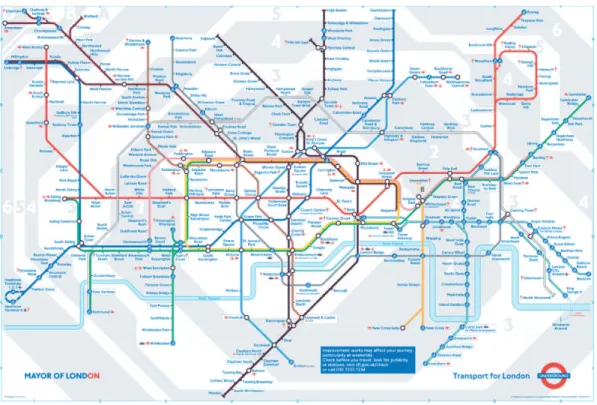
1.2 The ’official’ map of the London Underground . . . 5
1.3 The Geographical layout of the London Underground . . . 6
1.4 The Geographical Map of London with the layout of the Tube included . . . 6
1.5 A Schematic of the Spatial Semantic Hierarchy [Kuipers 00]. Closed-headed arrows represent dependencies, open-headed arrows represent potential informa-tion flow without dependency. . . 12
1.6 Illustration of a LAMP Mission . . . 15
1.7 Sample Layout of a corridor with places set next to Landmarks . . . 17
1.8 Representation of the Topological Path in the form of Graph . . . 19
1.9 A hierarchy of representations . . . 21
1.10 Recovering the Reference Sequence View index using a Single View . . . 24
1.11 A schematic of the Place recognition procedure using the context of the Refer-ence SequRefer-ence. . . 26
2.1 Creating Binary Features from Sensor Views . . . 37
2.2 Toy FIM to demonstrate the working of the Bernoulli Mixture Model . . . 44
2.3 The Robuter platform at the Dept of Mech. Eng., Aveiro . . . 44
2.4 Representative scans from a Reference Sequence of 118 scans taken along a Hallway . . . 46
2.5 Representative images from a Reference Sequence of 67 images. . . 47
2.6 Explaining the non-inclusion of features not visible during Place Recognition . . 50
2.7 Place Recognition Results for features from a single Camera using Bernoulli Mixture models . . . 53
2.8 Representative Image from a Reference Sequence of 118 images taken by Cam-era #1 along a hallway . . . 54
2.9 Representative Images from a Reference Sequence of 118 images taken by Cam-era #2 along a corridor . . . 54
2.10 The Feature Incidence Matrix for a Reference Sequence of 118 Views the Hallway 55 2.11 Place Recognition Results For different Sensor Combinations using Bernoulli Mixture models . . . 56
2.12 Illustrating the Prior Distribution across the Views of the Reference Sequence . . 57 v
2.13 Overview of Place Recognition Results For Different Sensor Combinations using Bernoulli Mixture Model . . . 59 2.14 An Information theory view of the Place-Recognition information offered by
each view . . . 60 3.1 Using an HMM to evaluate the current robot position at time ’t’ . . . 66 3.2 Rabiner’s [Rabiner 89], description of problems for HMMs. . . 67 3.3 The Markov Chain behind the sampled Reference Sequence . . . 69 3.4 The Single Step Transition matrix for the Places along the Topological Path . . . 70 3.5 The modified Markov Chain for Place Recognition . . . 73 3.6 An Example of Profile HMMs used for Protein Alignment . . . 73 3.7 Illustration of the robot Motion Model . . . 75 3.8 Observation Probability Matrix and Transition Probability Matrix for the
Com-plete Markov Chain used in the HMM . . . 77 3.9 The 4 steps of the Viterbi Algorithm . . . 79 3.10 A schematic of the Algorithms used to perform place recognition . . . 80 3.11 Comparison of place recognition with and without recourse to HMMs-Varied
light conditions. . . 81 3.12 Comparing Place Recognition with and without HMMs . . . 83 3.13 Representative images from Camera #1 and Camera #2 for the Reference
Se-quence of a Hallway . . . 84
4.1 Sensory events in the topological are represented using a conditional distribution, where
the experiment of viewing a particular sensory event is conditional on the particular state
of the environment(O1, . . . , O5are sensory events). . . 90
4.2 Description of the Environment Familiarisation and Place recognition tasks. . . . 90
4.3 A schematic for the comparison with multiple trajectories (sections of different
Refer-ence SequRefer-ences or Topological Paths). . . 93
4.4 Viewing the Global topological map as a collection of multiple, non-overlapping paths . . . 100 4.5 Example of View similarity calculation in the literature . . . 102 4.6 View similarity matrices are shown for experiments described later in section 4.5.
The similarity (lighter indicates greater similarity) between views is calculated using a metric based on the number features that the views have in common after having reduced the dimensionality of the feature space using the Bernoulli Mix-ture Model. In this figure white values in the matrix indicate greater similarity and black indicate no similarity. . . 103
4.7 Merging of Segments of a data Sequence with the topological representation of another
Path. . . 104
4.8 The layout of 2 sequences to be merged . . . 107 4.9 Experiments in the Merging of Topological Paths - 2 Reference Sequences . . . . 108 4.10 The layout of 8 sequences to be merged . . . 110 4.11 Representative images from distinct Reference Sequences - Camera #1 . . . 112
LIST OF FIGURES vii 4.12 Representative images from distinct Reference Sequences - Camera2 . . . 113 4.13 The pairwise comparison of Sequences to generate merging hypothesis. . . 114 4.14 Experiment 2: The variation inP (s) over the path taken by the robot . . . 115 5.1 An overview of the general architecture of the robot system . . . 120 5.2 The Low Level Robot Architecture . . . 122 5.3 The Robuter platform at the Dept of Mech. Eng., Aveiro . . . 124 5.4 The Segway Robotic Mobile Platform (RMP) and the sensor platform. . . 125 5.5 The Tactical layer in the Robot Architecture . . . 126 5.6 Inter-process communication using CARMEN . . . 129 5.7 Program Interface for Environment Familiarisation . . . 130 5.8 Program Interfaces for place recognition . . . 132 6.1 Representation of long outdoor path using a FIM. . . 138 6.2 Graph model of the Topological path . . . 139 6.3 Depiction of merging of topological paths. . . 139 6.4 Depiction of compacting of Reference sequences. . . 139 6.5 Viewing perception as a transmission of a single bit across a noisy, non-symmetric
binary channel. . . 143 6.6 HMM model that follows the Mealy Model with Explicit state duration, from
[Mitchell 95a] . . . 146 6.7 [Comparative] definition of the Sequential Machine Learning Problem [Schuster 99].147 A.1 A KD-Tree created from a set of 3-Dimensional point . . . 152 B.1 Illustration of Line Fusion using the iterative-end-point-fit Algorithm . . . 159 B.2 Classification of Passable and non-passable doors using Range Scan Data . . . . 161 B.3 Classification of Doors into Passable and non-passable using range scan data . . 161 C.1 Examples of the Behaviours available for the mission . . . 165 C.2 Creating a mission of plan view of a path semantically . . . 168 C.3 Creating a mission semantically: Plan view of path to be taken by the robot to
enter a room . . . 169 C.4 Feasible behaviours while Robot is in front of a door . . . 169 C.5 Feasible behaviours when Robot ’sees’ a distinctive scene . . . 170
Nomenclature
αc The mixture component coefficient for componentc.
αreg The weighting proportion of the motion model estimate for the prior probability of the
next place-recognition.
λ The parameter set,hN, M, {πi}, {aij}, {bi(n)}i, of the Hidden Markov Model.
L The likelihood of a [conditional] event.
V The FIM, or the complete set of views/vectors as collected during the Environment-Familiarisation stage.
π The initial probability distribution over the hidden states of the Hidden Markov Model. πi The initial probability distribution for the hidden statei of the Hidden Markov Model.
Q
Represents the product operator.
PK
k=1 Represents the sum operator with the indexk varying from 1 to K.
Θ Represents the complete parameters of the Mixture model.
Θ∗ The Mixture Model parameters obtained after terminating the EM algorithm.
Θc A single componentc of the Mixture Model.
aij The probability of transiting from [hidden] statei to state j in the Hidden Markov Model.
bi(n) The observation or emission probability for the symbol biat the placen within the Hidden
Markov Model.
bi,j(Ot) The observation or emission probability for the symbol Ot at the transitioni, j within
the Hidden Markov Model.
C a constant, represents the total number of components in the BMM. c an index, represents a component in the BMM.
F A single [named] feature in a view/vector. ix
H(Vk/K) The conditional information between the distribution of Vk, given thatK is known.
I(Vk : K) The mutual information between the distribution of VkandK.
j An index, employed to denote a particular feature,j.
K A constant, typically indicating the number of Views in the original sampled Reference Sequence.
k An index, employed to denote a particular view,k.
k∗ The estimated place as obtained by applying the Max-likelihood criteria to the Belief over
the indices of the Reference Sequence.
Ks A constant, indicating the number of Views in the original sampled Reference Sequence,
s.
ks An index, employed to denote a particular view from Reference Sequences, ks.
M The number of [hidden] states in the Hidden Markov Model.
N The number of [visible] Observations/symbols in the Hidden Markov Model.
P (Vobs/Θc) The similarity between the observation Vobs and the component c of the Mixture
model.
P (Vk/Vobs) The probability of the currently observed view/vector Vobsbeing matched to View/vector
VkinV, the Reference Sequence.
P (Vobs/Θ) The probability distribution of the observation Vobs over all the components of the
Mixture model.
T The total number of Observations in the Hidden Markov Model.
t The variable indicating the Observation number in the Hidden Markov Model, t varies from {0. . .T}.
Vk A single view/vector with an index k within the FIM, V, composed of multi-sensorial
features.
Vobs The currently visible View/vector with the features that are currently observable.
Z Hidden or incomplete data in a Mixture Mode.
zk The vector from MatrixZ corresponding to the View/vector Vk.
zkc The value of the MatrixZ corresponding to the View/vector Vkand componentc. jVk Value of the Feature ’j’ in the View/vector Vkof the Reference Sequence.
LIST OF FIGURES xi
jVobs Value of the Feature ’j’ in the observed View/vector Vobs.
jΘc The value corresponding to Feature ’j’ of Bernoulli Mixture Model Component ’c’.
#traj length of trajectory, number of views in the trajectory.
Camera #1 Camera looking forward in direction of motion. Camera #2 Camera looking laterally to one side of robot.
LRF SICK Laser Range Finder facing forward in direction of motion. BMM Bernoulli Mixture Model.
costj costj is a penalty term for featurej with values between 0 and 1.
EM Expectation Maximisation method as applied to evaluate the parameters of the BMM. H(S) The entropy of the random variable S.
log() Represents the log operator.
Chapter 1
Introduction
Over the last two decades there has been enormous progress in the field of robot navigation, with techniques being borrowed from fields as diverse as biology, signal processing and data-mining, to name a few, to solve the problems of Map-building and robot localisation. With improvements in the computational power that is available on modern PCs and reductions in the cost and in the size of components, the past few years have seen an acceleration in the attempts to apply the lessons learned within University research laboratories to solve real world problems involving autonomous vehicles. Such attempts involve assembling a host of technologies to create complex albeit reliable systems. This endeavour is expected to continue over the foreseeable future with an ever greater emphasis on the simplification of the machine interface with humans and with other machines.
Autonomous Robot Navigation is an ongoing and still a difficult problem to solve. Although advances in the science of localization and mapping accompanied by great improvements in computing hardware have yielded satisfactory results for small to medium indoor environments, substantial challenges remain.
According to [Filliat 03] basic map-based navigation depends on three processes
• Map-learning: the process of memorizing the data acquired by the robot during explo-ration in a suitable representation.
• Localisation: the process of deriving the current position of the robot within the map. 1
• Path planning: the process of choosing a course of action to reach a goal, given the current position. The definition of ’path planning’ varies with the time horizon and the nature of the motion or action that must be planned for.
Amongst the authoritative reviews of the process of creation of maps, Sebastian Thrun’s [Thrun 02a] ’Robotic Mapping: A Survey’ counts as a still valid and relevant introduction. As Thrun mentions, most of the successful state of the art methods in Localisation and Mapping are probabilistic in nature, albeit some methods are less overt than others in the representation of the uncertainties that affect sensing and robot control. In a similar vein Fox et al. [Fox 03], attempt to classify the well known approaches in mobile robot navigation focusing on the differences in the models that are used to represent the environment and the position of the robot. As a result of the legacy of ultrasound range sensors, many of the more successful maps still are actually probabilistic representations of free-space boundaries.
This thesis applies a selection of techniques that are borrowed from other disciplines to ad-dress the problems facing robot localization. These techniques are meant to aid mobile robots in the navigation of environments that are habitually frequented by human beings.
Localisation methods place the robot at that place (or at more than one place) in the envi-ronment which best explains its current sensor data. The choice of the Localisation method is usually a function of the type of map that is used.
We have addressed a particular type of localisation problem: positioning the robot somewhere along a known path. The information that the robot is given about its environment, the map, is given to it in sequential form, corresponding to the things that it will sense if it moves down the correct path.
By keeping the planning and the execution of robot motion out of the purview of the work described in this thesis, focus has been retained on the creation of a representation of the envi-ronment and on the localisation of the robot within this representation.
Our idea for robot localisation and the outline of the proposed solution are described in the next section. This description of the problem will be followed by a section that attempts to provide another way of looking at maps that have been described in the literature. This review
1.1. PROBLEM DESCRIPTION 3 focuses on maps from the perspective of map events. Section 1.3 will provide a backdrop for a more detailed description of the problem that this thesis addresses. The section 1.4 introduces the main ideas that will be tackled in the remainder of the document and presents a brief layout of the thesis document.
1.1
Problem Description
Imagine a situation in which our friend Juliana is journeying, by car, to a meeting at a house in the country. Juliana stops at a petrol station to ask for directions. The clerk at the petrol station provides Juliana with a sequence of descriptions of the environment that she will encounter as she progresses from a known landmark, say, the petrol station, to her final goal, as in Fig. 1.1. The clerk also provides Juliana with a sequence of instructions that Juliana must execute, instructions that are concomitant on the things that she will see as she successfully makes her way to her goal, the house.
The clerk tells Juliana that a little down the road, after passing the petrol station, she will come across a road junction. The road junction, is like many that Juliana might have previously come across. Our guide does tell her that this intersection is special because a bridge will be visible from it and because there will be some conspicuous trees that will be visible to the her right-hand side. Juliana is instructed to turn right at this junction and drive a few hundred meters till she arrives at her destination, at the house.
This sequential way of providing an agent with the expected observations against which the agent can localize itself and perform the required actions is associated with the execution of a definite mission or program. It does not require that the representation of the complete environ-ment be provided at once and the actions that must be performed at each step are dependent on the observations.
Applications for such a way of representing the environment would include, for example, interfaces of social robots that interact with humans, receiving and relaying environment maps in a way that is more intuitive and efficacious to the completion of a mission. If Juliana came to be substituted with a computer that guides and runs the vehicle, a petrol station clerk (or a virtual
...you will reach an intersection, where… 1. You should see a bridge ahead 2. You should see trees on your right
Turn right at the intersection
You will arrive at the house
..after passing a petrol station...
Figure 1.1: A sequential conveying of expected observations might be sufficient to successfully navigate along the Path. This is similar to the way instructions are given to people to allow them to complete a task or mission, in this case, arrive at the house.
clerk as the case may be) might still be able to provide a sequential description of a path and the instructions that are required to complete the mission.
Guiding a robot by providing only a sequence of expected sensor data opens a whole new set of possible applications that could involve a more intuitive interaction with humans. Such a concept, however, opens up new problems, namely in the question of how the sequence is to be represented and how data association is to take place.
This thesis seeks to contribute to the discussion of how to best exploit the sequential descrip-tion of a environment to effectively perform localisadescrip-tion.
1.2
Taxonomy of Maps used for Robot Navigation
The map of the London Underground, seen in Fig. 1.2, is one of the most recognizable maps around. This map is instantly associated with the Metropolitan rail road and it has been adopted as a template by urban rail transport planners the world over. The purpose of such a map is to help travellers plan their journeys. The map is remarkable for the ease with which passengers can identify stations lying on the same line, plan transfers to other lines and evaluate the cost of the complete trip.
1.2. TAXONOMY OF MAPS USED FOR ROBOT NAVIGATION 5
Figure 1.2: The ’official’ map of the London Underground.
In the Fig. 1.2, along each line, the map indicates the names of the stations and the order of appearance of the stations. At most, the map maintains the proportions of the distances between stations lying on the same line. It has information about the bus and train services that users can access upon exiting a station. This map does not seek to accurately represent the distances between stations and the overall layout of the stations with respect to each other. This topological map of the underground does not reveal how far, geographically, a station on one line is from any other station on the same or on a different line. Also, the map provides information only on events occurring at certain finite number of places, the stations. Information about places lying between stations is non-existent.
There are applications for which this map is not the most appropriate representation of the tube network. For example, to a first time visitor to London, the Fig. 1.2 might not be sufficiently informative to decide whether it is worth just walking between a pair of stations, rather than wait for the next train that is delayed. The same map might, like-wise, not be an appropriate map for maintenance and emergency services.
Figure 1.3: The geographical layout of the London Underground.
Figure 1.4: The actual geographical map of the London Underground with Surface features included.
1.2. TAXONOMY OF MAPS USED FOR ROBOT NAVIGATION 7 For these users, a geographical map of the tube, like the one shown in Fig. 1.3, would be far more helpful. Such a metric map lays out the stations and the lines according to their geograph-ical coordinates. This a map allows comparisons to be made of the distance between every pair of stations and of points lying on the lines, in between the stations. Additional information, such as ground-level features can be added to this new geographical map can also be represented in the same coordinate system, as depicted in Fig. 1.4.
The geographically accurate maps seen in Figs. 1.3 and 1.4 include large regions that are not covered by the underground network (and hence are not useful to commuters). The additional information has also resulted in lines that are difficult to follow, visually, and the accompanying text is sometimes small or uncomfortably positioned.
The additional information provided by the geometric or metric map improves the usability of the map by non-passengers. However, it is not the most useful map for commuters who simply want to execute a journey from station ’A’ to station ’B’ within the London Underground system. This example is an demonstration of a situation involving localisation where sequential, topological representation of the environment is more useful than precise metric positioning.
1.2.1
’Maps represent sensory and motion events...’
From the point of view of the theory of probability, maps represent events that can occur when a robot interacts with the environment. This interaction typically includes the motion of the robot and the sensing that can take place at any position. In other words, a map is a set of features, from a sample space of sensor events and a set of positions which the robot can occupy, a sample
space of positions. Brief definitions of Sets, Sample Spaces and Events are included below.
Set: A set, A, is an aggregate or collection of objects. The members of the set A are called the elements ofA, or ∈ A and, if x is not an element of A, x /∈ A...’ [Hines 90]
Experiments and Sample Spaces: Sensing the environment is the execution of an
experi-ment whose outcome cannot be predicted with certainty, being thus denoted as a random exper-iment. Despite the fact that the outcomes cannot be predicted with certainty, it is still possible to identify the set of possible outcomes, known as the Sensory Sample Space of the experiment.
Depending on the type of outcomes, Sample Spaces can be classified as discrete and continuous. Robot motion can also be viewed as another experiment wherein the outcome of a particular robot motion cannot be predicted with certainty.
Events: An event is the outcome of an experiment. Static maps contain events that can be
sensed by the complement of sensors that the robot possesses. Sensory events can be simple, such as detecting whether a particular region in the environment is free or occupied, or complex, e.g. the detection of a particular 2D pattern from observed data that is acquired at multiple positions. Motion events are very summarily addressed in the course of this document.
Over the sections 1.2.2 through 1.2.4, three types of environment representations are re-viewed with a view to scrutinize the differences that exist at the level of the representation of sensed events. In this review, relatively little attention has been given to methods that are used to create the maps and to the events that populate the map. For a discussion along these lines [Thrun 02a] provides an useful comparison.
An important point of discussion is the idea of Robot-centered versus World-centered repre-sentations of the environment. At the time of building maps of the environment most methods transform what the robot has sensed (which, by definition, is the robot-centered representation) into a centered representations, using the estimate of the position of the robot in the world-centered representation. Range sensors, for example, return a sample of distances to the nearest obstacles along some finite number of directions, thus returning robot-centered representations of the robot’s neighbourhood.
Events on a geometric or topological map are usually termed, sometimes interchangeably, as landmarks, objects or features. These landmarks and features are sensory events the robot can identify, segment and recognize. The selection of the landmarks or features is a very relevant topic while discussing maps and a wide range of features and landmarks have been used within such maps. In robot platforms equipped with cameras local image features such as edges, cor-ners, have been used. Topological maps have also included parametric groups of 2D and 3D point clouds produced by range finders and stereo cameras. The events might be all inserted into the same space of events or in different spaces.
1.2. TAXONOMY OF MAPS USED FOR ROBOT NAVIGATION 9
1.2.2
Geometric Maps
World-centered or geo-referenced representations lead to maps such as the geometrical map of the Underground shown in Fig. 1.4 where all the features are inserted in the same coordinate system. Geometric maps allow the calculation of the distance that separates any two features that are included in the map. When used by robots equipped with range scanning sensors, geo-metric maps frequently include ’distance’ events: i.e. the features that are represented must have definite coordinates and the robot must posses sensors that can measure the distance to the source coordinates of these features. In fact, as the first robots were equipped mainly with sonar and laser range sensors, geometric maps were used early on [Elfes 87].
Since geometric maps are, by their very nature, world-centered distributions, the robot-centered data must be translated and rotated appropriately in order to be incorporated into the world-centered representation. This incorporation procedure is usually performed by creating a physical model of the behaviour of the sensor in the environment and by making convenient assumptions about how to associate the different measurements.
In order to account for sensor noise and to allow an easy update of the map when new data becomes available, there occurred a shift towards discrete representations, to the so-called occu-pancy maps or evidence grids. Given the nature of range sensors in use, the limited computing and memory available and the need to map ever larger indoor spaces, the maps started out as a deterministic 2-D representations of the extents of the sensed open space. These were quickly improved to incorporate the uncertainty in sensor readings and the resultant inconsistencies that are bound to occur when the robot passes through the same stretch of environment multiple times. Representing only the free-space boundaries in a geometric map or a single type of feature within a map presents both advantages and drawbacks. The advantages are the lower level of complexity required to register and incorporate the data from a single sensor. This is an im-portant advantage since the sensor models may be very different and since the data from each sensor-centered representation must later be incorporated into a common map. The drawbacks of such maps are that the reduced variety of local regions in the maps results in a poor capability to determine how to register the sensor-centered data gathered at any instant with the map. This
re-sults in an increase in situations that suffer from the well-known problem of aliasing and from the general difficulty of data-association between the sensor-centered measurements and the world-centered representations. Additionally, in an effort to make the localisation of the robot tractable, non-linear motion equations are frequently linearised resulting in a gradual accumulation of an unbounded positioning error.
The Expectation Maximisation (EM) technique and other incremental mapping techniques have been applied to reduce the severity of these problems. Further evolution of the method might improve on the techniques required to perform registration. Other methods might also add to the capability of adding new features to the map and to the capacity to create, maintain and use larger maps effectively.
Geometric Maps enforce a consistency on the distances between every pair of places by defining a single coordinate system. If a sensory event must be represented in the geometric map, it must first be possible to represent it within the coordinate system of the map. This step ensures that the joint probability distribution of the events will be valid and that putting together sensed events from different sensors will result in consistent probability distributions. Therefore, data fusion requires the registration of the various sensors into the same single coordinate system within which all the features will be represented.
1.2.3
Topological Maps
Topological maps, on the other hand, need not have a consistent coordinate system in which all the map sensory events are represented. Topological mapping methods might use information about free-space boundaries or obstacle locations and in some cases local metric maps might be created and used in order to communicate results or interact with operators, e.g. [Silver 04] or to improve the place-recognition capability of the robot. The latter approach allows the use of place-recognition capabilities developed within the context of geometric maps, to create compact graph representations of the overall environment, appropriate for the creation of maps for larger environment [Thrun 98]. While geometric mapping is still popular, some researchers increas-ingly feel the need to adopt mapping techniques for what are called Large-scale environments.
1.2. TAXONOMY OF MAPS USED FOR ROBOT NAVIGATION 11 Large-scale environments are defined as environments that cannot be observed all at once, using the sensors that the robot is equipped with [Savelli 05]. For this the drawback attributed above to geometric map-building methods must be addressed.
One such popular approach is to use a metric map created using range sensors and reduce it to a one-dimensional representation using a Generalised Voronoi Diagram. Such a method, while not having to store the range measurements within the topological map, results in the storage of a ’high-level’ feature which can be easily sensed from the range scan sensor data [Choset 01], [Silver 04].
Increasingly, alternative methods have been developed to create Topological maps for nav-igation and Localisation. An important class of such methods are termed as appearance-based or view-based methods. In [Ulrich 00], Ulrich and Nourbakhsh, histograms are used as features to mark places in the environment. A distance metric based on the Jeffrey divergence between histograms is utilized as a metric and a set of adjacency Maps are utilised to account for robot motion. A generation of new methods for creating topological maps succeeded the seminal work called Topological SLAM by Choset and Nagatani [Choset 01].
Since topological maps typically contain sparser information than metric maps, they must contain better data-association methods, either in the form of a richer map-feature set or in the form of better global localisation algorithms.
In the context of a topological map for mobile robots, places are distinctive points in the environment that the robot can occupy or has previously occupied, at least once. The topological map can also specify whether a transition between a pair of places is possible and can include additional information regarding these possible transitions.
1.2.4
Hybrid Maps
Hybrid approaches to map-building are usually employed in applications that require the charac-teristics and advantages of both geometric and topological maps.
By definition, hybrid mapping would include a geometric representation and a topological representation, that is usually linked in some way to the geometric one. One of the earliest and
Figure 1.5: A Schematic of the Spatial Semantic Hierarchy [Kuipers 00]. Closed-headed ar-rows represent dependencies, open-headed arar-rows represent potential information flow without dependency.
possibly one of the most well known approaches in this category is the Spatial Semantic Hierar-chy or the SSH developed by Ben Kuipers [Kuipers 00]. The SSH, shown in Fig. 1.5, is described as ’a model of knowledge of large-scale space consisting of multiple interacting representations, both qualitative and quantitative’. The representation of the environment is maintained in the form of a hierarchy of maps each of which allows some abstraction of the perception and in-teraction of the robot with the environment. These hierarchical’levels’ include a Causal layer, a Control layer, a Topological layer and a possible (if enough information is available) a high-level Metrical layer. The advantages gained from using SSH or similar hierarchical model of repre-sentations is that incomplete information or uncertainty in the information is handled in different forms depending on which particular Localisation or navigation problem is to be solved. Lo-cal metric maps help to perform place recognition, [middle-level] topologiLo-cal maps help create consistent maps in the face of challenges such as loop-closing problems, and the global metric maps maintain an overall consistency in the global position of the robot. Savelli and Kuipers [Savelli 05], utilise a probabilistic modelling of motions behaviours to move the SSH from a rule
1.3. REPRESENTING PLACES SEQUENTIALLY ALONG A PATH 13 based method to a graph-based topological map framework based on Bayesian networks.
There are also attempts to utilize graph-based approaches to solve particular problems that appear at the time of creation of metric maps. Methods such as [Folkesson 04], use graphical methods to maintain hypothesis for map expansion and closure, i.e. graph-like methods are used to maintain multiple map hypothesis of the main map which is geometrical.
There are works that enhance the applicability of metric maps and the ability of users to interact with these such as representing individual objects. In [Limketkai 05], Limketkai et. al. store the representation of objects (some of which might also be used by persons) using a technique called Random Markov networks.
As in the case described in the section on topological maps, in certain mobile robot systems, there is a need to maintain local geometrical maps around certain regions. The reason for main-taining these maps however is not to perform place recognition, but to allow better and faster planning of trajectories and re utilization of the map by robots equipped with different sensor configurations [Konolige 04].
1.3
Representing Places sequentially along a Path
A Mission, from the Latin Missum, refers to persons sent or appointed to perform any service; a delegation; an embassy. In the context of mobile robot navigation, a mission can be defined as
an ordered series of descriptions and instructions given to a robot that will take it from one place in the environment to another.
In the context of this work, a Mission consists of a sequential description of situations and motion behaviours that the robot will sense along the way. We refer to the sequence of descrip-tions as the Reference Sequence. When a sequence of behaviours or acdescrip-tions are needed to move the robot from a point, A, to another, B, are added to the Reference Sequence, a robot Mission is defined.
The Mission is communicated to the robot in the form of a string of motion behaviours that are concomitant on the expected observation. Initial development of the specification of such mission strings was based on previously developed work [Santos 01] and is described in
Appendix C. The lack of previous experience with semantic representations and has led us to concentrate on the sequential representation of sensor information.
Thus, instead of manually creating a mission string and communicating it to the robot, the robot is driven along a path during an Environment or Path familiarisation phase. Since the motion of the robot has not been integrated into the representation of the environment, we will normally deal only with the Reference Sequence in the remainder of the thesis. It is our opinion that motion behaviours could be inserted into this Reference Sequence at a later stage to create a Mission if the capability of the system to recognise places and localise itself is verified.
Two distinct questions must be answered for a Reference Sequence to be specified in the form of a sequential description of the environment. These are:
1. How are observations represented in the Reference Sequence?
2. How can the sequential description of observations improve the localisation within the Reference Sequence?
These are questions for which, answers will be sought, over the course of the next two chap-ters. The exploitation of information, that is implicit in the sequential description of sensor data, that results in better place recognition is the key element that differentiates the approach described in this work from other map-building approaches in the literature.
1.3.1
Some Previous Work
The genesis of our attempt to navigate along a path by localising the robot within a Reference Sequence lies in previous work. A mission programming tool was developed for use on the robot platform at the Mobile Robotics and Automation Laboratory (LAR) of the Department of Mechanical Engineering, of the University of Aveiro [Santos 01]. This tool, the Language for Autonomous Mission Planning (LAMP) [Santos 01] could be used by an operator to set up a mission, using a qualitative description of the topology of the environment. The kernel feature of LAMP is that a robot mission may be planned and executed by utilizing the approximate position and layout of entities to trigger the beginning and the end of individual phases of the mission.
1.3. REPRESENTING PLACES SEQUENTIALLY ALONG A PATH 15 Although odometry is utilised to execute individual stages of the mission, the initialisation and termination of each stage resets the odometry effectively removing any accumulated error. Individual stages are set up either as closed loop feedback or as open loops. This method partially obviates the necessity of the robot knowing where exactly it is in the environment. LAMP still required a boot-strapping localisation procedure.
LAMP allows the environment to be described in terms of obstacles that the robot will sense around itself as it executes the various stages of its mission. The robot motions that can be in-cluded in a LAMP mission include: wall following, obstacle avoidance, in-place turning, execut-ing a short trajectory in open-loop mode and crossexecut-ing narrow openexecut-ings. An illustrative mission comprising of 11 mission stages and the plan view of the result of each stage is described in Fig.1.6.
1. MOVP MV 2 0 PS 2 USL 500 SEN 1
2. MOVE LV 0 AV 10 ANL 90 3. MOVP MV 20 USL 1000 SEN 1 4. MOVE LV 0 AV 10 ANL 90 5. MOVE LV 20 DIL 1500 6. CROSS
7. MOVE LV 10 USL 3 00 SEN 1 8. MOVE AV 2 0 ANL 90
9. MOVP MV 2 0 PS 2 USL 500 SEN 1
10. MOVE AV 20 ANL 90
11. MOVP MV 20 PS 1 USL 300 SEN 1
Figure 1.6: A navigation mission with associated LAMP code.
LAMP served to demonstrate the concept that the sequential description of the expected perception could be used to trigger the start and end of a sequence of motion behaviours that
could propel the robot from the beginning to the end of a mission. It does suffer, however, from limited sensory capabilities that, in turn, limit its application in real-world environments.
LAMP handles its single feature in a trivial manner with the sonar sensors indicating the presence or absence of an obstacle. Its inability to handle more than one type of feature means that it cannot be applied to more conventional robot platform navigating robustly within a real-world environment. An expansion of the method to include multiple sensors would have to include more sophisticated methods to integrate the different features.
The application of LAMP-like methods would be much enhanced if realistic methods to create LAMP missions were developed and if vision and range scan features were used within the missions to provide robust robot localisation capabilities.
1.3.2
Individual Place Recognition and the temporal context of Places
Consider a hypothetical robot equipped with a special sensor that allows it to identify certain environmental features. With the aid of this sensor our robot can identify doors, corners and walls. To keep this exposition simple, it is assumed that the robot can sense these landmarks only if they lie close to it.
Supposing our robot is lead on a sightseeing tour of a building. At regular intervals of time our robot looks around, identifies the landmarks that are in sight and records the sighting in a table. The sequential description of what the robot found on the path has been represented in Table 1.1 and a plan-map of a section of the environment would appear similar to Fig. 1.7.
If the description of the observations seen from places 1 through 10 in the environment de-scribed in Table 1.1, were provided sequentially to a robot we would denote it as the Reference Sequence. Each place is associated with particular landmarks and with a motion behaviour. By correctly identifying the place at which it finds itself, the robot can recover the actions that are required to get it to the next way point/place. If the actions that led the robot from each place to the next place were added to the Reference Sequence we would obtain a robot mission. A mission that would allow the robot to move from the starting place 1 to the final place 10 would have been created.
1.3. REPRESENTING PLACES SEQUENTIALLY ALONG A PATH 17
Place with Abrupt Corner Landmak
Place with Door Landmak
Place with Other Intersting Landmark
Figure 1.7: The figure illustrates a sequence of places, in a corridor, where each place is recog-nised because of the landmarks perceived at that place.
Table 1.1: Table of Places included in the Reference Sequence for the path depicted in Fig. 1.7.
1 2 3 4 5 6 7 8 9 10
Corner Landmark 0 1 0 0 0 0 0 0 0 0
Door landmark 0 0 1 1 0 1 0 1 1 0
Our hypothetical robot has the ability to distinguish between a limited number of landmarks. As a result it is not always possible to accurately distinguish one place from every other places. In particular, using a single observation, it is impossible to distinguish between the various ’door’ places, because the doors are ambiguous landmarks (and the same applies to the walls). In the context of the mobile robotic Localisation problem, this challenge is commonly referred to as ’perceptual aliasing’.
There is another problem, one that has not been described in this example, the problem of ’Scene Variability’, in which the same landmark appears differently at different times, either because of changing observation conditions, noisy sensor readings or as a result of the robot moving within dynamic environment (moving objects or changing nature of the objects).
The problems of perceptual aliasing and scene variability can be diminished by using a larger set of landmarks or by using combinations of landmarks, such that each combination of land-marks is unique. Unless a sufficient number of unique landland-marks are available, it is going to be difficult to increase the size of the map whilst simultaneously ensuring reliable place recognition. A logical improvement to using a single observation of landmarks would be to observe the order in which multiple observations of landmarks are made by the robot. In practice, the cost of implementing algorithms to identify different and unique landmarks is high, and the twin prob-lems of scene variability and place aliasing is so common, that virtually all localisation algo-rithms make inferences from observing multiple observations. This accumulation of information is done in two ways.
The most common method is to utilise an estimation filter to accumulate the information gained by observing a sequence of observations. At the time of each observation, the evidence gathered over the multiple previous observations are added to the current observation in the form of a prior probability.
The other approach is to gather the combinations of features that are viewed while travelling along a path to create larger, and hopefully more unique combinations of landmarks. Such an approach can be utilised all the time as in the topological approach Kuipers [Kuipers 02] or occasionally, when there is a greater risk of place aliasing, such as when applied to the problem of loop closure while map building [Newman 06].
1.3. REPRESENTING PLACES SEQUENTIALLY ALONG A PATH 19
1.3.3
Modelling the Sequence as a Topological Path
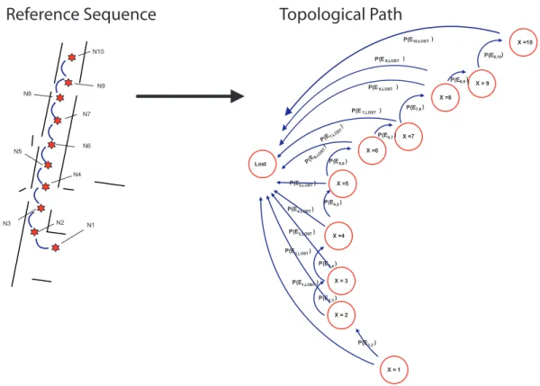
Reference Sequence
Topological Path
N1 N2 N3 N4 N7 N6 N5 N8 N9 N10 X = 1 X = 2 X = 3 X =4 X =5 X =6 X =7 Lost P(E2,3 ) P(E3,4 ) P(E4,5 ) P(E5,6 ) P(E6,7 ) P(E1,2 ) P(E2,LOST ) P(E3,LOST ) P(E4,LOST ) P(E5,LOST ) P(E1,LOST ) P(E7,LOS T ) P(E6, LOST ) X =8 X = 9 ) X =10 P(E7,8 ) P(E8,9 ) P(E9,10 ) P(E10,LOST ) P(E 9,LOST ) P(E 7,LOST ) P(E 9,LOST )
Figure 1.8: Representation of the Topological path as a Graph of Places arranged sequentially. The graph itself is created from a sequence of sequentially obtained sensor views.
Within the scope of the discussion from the last sections, a graph of places denotes an ordered set of places, along a path in the environment, at each of which the robot perception is defined. Importantly, the places that are represented in these graphs are not identified by their physical position in a common coordinate system. Some perception or landmark is associated with each place in the Topological path as seen in Fig. 1.8.
Localising the robot in the path and consequently in the graph of places that represents the Topological Path entails estimating the place that is currently occupied by the robot.
1.3.4
The Place of the ’Lost’ Robot
The Reference Sequence is created by sampling the environment, which is a discrete procedure. It is not possible to take observations continuously and often it is not very feasible to sample the
environment at very high rates. Doing so would seriously limit the size of the environment that can be usefully represented.
In this work, a definition of the Place of the Lost Robot (no relationship with Isaac Asimov’s Little Lost Robot), or theLost_P lace was found to be useful. The Lost_P lace represents the positions in the environment at which the robot does not know what combination of landmarks can be seen.
In the graph of places, theLost_P lace, has also been added to the previously defined places. The Place of the Lost Robot is useful in two distinct situations: in the first, the robot has simply no recollection of a particular combination of features currently in view because of the problem of sampling. In the second situation, an unintended maneuver, or a substantial change in the environment results in the robot not recognising a place that is represented in the Reference Sequence.
Thus, theLost_P lace represents all the possible places that the robot might encounter in the environment that are not represented in the graph of places and the locations in the environment that fall outside this path.
In the literature, recognition at places that are difficult to identify is often done by attempting some sort of back-tracking. In this thesis, behaviours to recover from a failure to localise are not implemented and the robot simply declares itself as lost. In other words, when a robot is at a Lost_P lace it is expected to eventually stop and declare itself as being ’lost’.
1.3.5
A hierarchy of representations
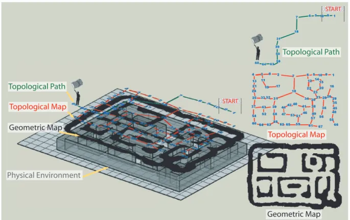
The proposal of the Reference Sequence as a representation of a topological path can be viewed in the context of map building algorithms that have been described in the literature. As a repre-sentation of the environment, the Reference Sequence contains the least amount of information. The hybrid geometric and topological maps presented by Thrun in [Thrun 02b] have been used as a comparison to our approach. The different amounts of information that are maintained by different representations can be viewed as giving rise to a hierarchy as seen in Fig. 1.9. As seen in the figure, the higher we move up the hierarchy, lesser is the information that is
1.4. PROPOSED ORGANIZATION OF THIS THESIS 21 60 64 6358 50 31 39 18 7 6 510 9 1 START START Geometric Map Physical Environment Topological Map Topological Path Geometric Map Topological Map Topological Path
Figure 1.9: Navigating the environment along a topological path can be looked at as a repre-sentation containing lower information as compared to a complete geometric or even a complete topological representation of the physical environment.
maintained.
The geometric map attempts to represent all the information that can be extracted by the sensors within a single joint probability distribution. This joint probability distribution is broken up resulting in the graph structure of the topological map where the perception is stored at the various nodes of the graph. The Reference Sequence maintains information pertaining to only a single path in the global topological map.
1.4
Proposed Organization of this Thesis
This thesis document is chapter-wise organised according to three successive objectives of 1) de-signing an un-biased place recognition method, 2) making use of the sequential context in which place recognition takes place and 3) modification of these techniques to improve the usability of
the methods.
When the robot navigates the environment using the Reference Sequence, a number of sources of uncertainty must be dealt with. There is uncertainty in the process of detection of the land-marks (due to noise and different perception conditions) and there is uncertainty in the accuracy of the motion along the Reference Sequence (due to dynamic environments). As compared to the term ’landmarks’, ’features’ are a more generalized form of representing the properties of current scene, since it avoids certain semantic difficulties that are associated with the use of the term, Landmark. A feature is taken to mean any artifact or property that can be extracted from a sensor view, be it from a Laser Range Scan or from an image or any other sensor data. This def-inition opens the way to using multiple features extracted from data from different sensors. Any feature that is chosen must be relatively robust to changes in the conditions of the observation. This thesis has made use of robust features that are extracted from images and from Laser Range scans.
Chapter 2 presents an algorithm to perform context-independent, non-informative prior, place recognition using a Bernoulli Mixture Model. In chapter 3, place recognition results are shown to improve when the currently observed view is compared with each view in Reference Sequence in the context of appearance with respect previous observations. In chapter 4, the problem of cre-ating topological maps from individual Reference Sequences (topological paths) is considered. Chapter 5 begins with the description of the complete system as implemented on two robots and lays out the architecture of the system and a brief description of the applications and libraries that were developed. Finally, chapter 6 lists the main contributions of this thesis and the resul-tant articles that were accepted at peer-reviewed conferences and journals. The close of this last chapter also provides an opportunity to present issues that were addressed but which could be solved in useful time and which now indicate the direction for future work.
In the remainder of this section, the proposal for place recognition using sequences of views from multiple sensors is described.
1.4. PROPOSED ORGANIZATION OF THIS THESIS 23
1.4.1
Place Recognition using a single View
A key issue of using a method based on features is the choice of the frame of reference. The fact that features must be extracted from a number of different sensors and pooled into a single set of multi-sensorial feature forces us to choose between choosing a single common frame of reference or ignoring the ordering and position information that the features possess within the frame of reference. The features extracted from an image or from a Laser range scan, each have their frame of reference. The ordering of the features in the coordinate system of the frame of reference of the sensor can provide substantial information to aid the matching of a view.
Because the features to be integrated are very different from each other, a registration or sensor calibration procedure would be required to integrate each additional type of feature. Ad-ditionally, it would be impossible to integrate features that provide bearing/distance from the robot with other features that have no such obvious property. Also, because features from dif-ferent sensors will not be inserted within a common coordinate system, the ordering information within a single view has been completely ignored while integrating the different features. If a need arises to include the information about the ordering between two or more features, this ordering can be explicitly included in the form of additional features.
The term ’Perception’ is used to signify both, the act of perceiving or sensing the world and also the result of this sensing. Given some sort of environment representation, robot Localisation involves using the ’Current View’ to help determine the likely ’Current Position’.
A schematic for such place recognition from a Single View is shown in Fig. 1.10. This figure depicts an Environment or Path Familiarisation stage at left in which a sequence of views are collected together. Each view is an index that refers to a particular place along the path taken by the robot during the Environment Familiarisation stage. Place recognition or localisation involves the recovery of this index by the comparison of the current observation with all the views in the Reference Sequence.
The current view is compared with each of the views in the Reference Sequence through a comparison of the features that appear in the views, using an appropriate algorithm. In order to be able to use the information from the sequence as efficiently as possible, it is important
St
e
p 1
: P
at
h
Fa
m
iliar
iza
tion
St
e
p 2
: P
lac
e
Re
cog
n
itio
n
Cu
rre
n
t V
iew
(image
s + sc
ans)
?
Se
q
uenc
e o
f S
ampled V
iew
s/
Re
fer
enc
e V
iew S
equ
enc
e
?
?
ST AR T F ig u re 1 .1 0 : T h e im ag e ill u st ra te s th e re co v er y o f th e Re fe re n ce S eq u en ce V ie w in d ex u si n g a S in g le V ie w . T h e so lu tio n in v o lv es re g is te rin g th e cu rr en t se n so r d at a w ith a p re v io u sl y g at h er ed se q u en ce o f V ie w s to fi n d th e b es t ’fi t’ o r ’m at ch ’.1.4. PROPOSED ORGANIZATION OF THIS THESIS 25 that the algorithm provide an unbiased estimate of the distance between the current view and each of the views in the Reference Sequence. When large numbers of features are employed to represent a view, it becomes increasingly difficult to design and use a metric that provides unbiased distances between views. This problem, often referred to as the curse of dimensionality [Bellman 61], results in the failure of matching. Given a noisy observation, it is more probable that any random view will be closer to the current view than the actual corresponding view in the Reference Sequence. For a distance metric to provide un-biased results on the high-dimensional feature data, some sort of dimensionality reduction is imperative.
The algorithm described by us, in chapter 2, as a solution to this problem is the reduction of the dimensionality of the ’space of features’ using a Bernoulli Mixture Model.
An important assumption that is required throughout the work described in this thesis is that the initial Environment Familiarisation stage must be performed in an environment that is as reliable as possible. In subsequent travel through the environment, statistical treatment of differences in perception allow the robot to handle changes in the environment.
1.4.2
Place Recognition using the context of the View Sequence
As was mentioned in section 1.3.2, despite the use of a large number of features, the twin prob-lems of scene variability and place aliasing implies that it might not always be possible to cor-rectly and uniquely identify a place using a single observation.
A better way would be to make an inference inference of the position of the robot in the Reference Sequence after collecting observations over a finite number of positions, as shown in Fig. 1.11. This approach would still utilize the distance metric used in the case of a single view and would still require dimensionality reduction methods to be able to make unbiased estimates using a large number of features. Such a scheme could improve the performance of the method by using a Prior Probability to favour the chances of matching latter observations based on the estimation results of previous observations.
Utilizing multiple views implies that the motion of the robot must be taken into account in some way. In this work, a simple model for robot motion has been employed to consider the

![Figure 1.5: A Schematic of the Spatial Semantic Hierarchy [Kuipers 00]. Closed-headed ar- ar-rows represent dependencies, open-headed arar-rows represent potential information flow without dependency.](https://thumb-eu.123doks.com/thumbv2/123dok_br/15823528.1082096/40.892.298.613.147.489/schematic-semantic-hierarchy-represent-dependencies-represent-information-dependency.webp)