AUTOMATION OF FLIGHT SIMULATOR PLATFORM IN IMMERSIVE
VIRTUAL REALITY
Alejandro R. Garcia RAMIREZ1, Alexandre A. dos REIS1, Marcelo G. GOMES-‐FERREIRA1, Altino CORDEIRO NETO1 and Amanda HAASE1.
1 Universidade do Estado de Santa Catarina
ABSTRACT
The development of new and complex aircraft stimulates, more and more, the development of flight simulators. A flight simulator reproduces the dynamic model behavior of an aircraft, so the user can interact with the Simulator more realistically. Due to the relevance of the theme, the Group of Ergonomic Researches in Design of the Department of Design of UDESC carried out the project and mechanical production of a robotic platform with six degrees of freedom (6 DOF) for the study of a flight Simulator in immersive virtual reality. This study deals with the automation of the platform developed in order to make the movements of the flight simulator feasible in an environment of immersive virtual reality. With this purpose the technologies applied are described and the results achieved have been presented up to the present stage of development. The research envisages improving the standards of movement generated by flight simulators.
KEY WORDS
Parallel robots, movement platform, flight simulator, virtual reality.
1. INTRODUCTION
A flight simulator is a machine used to train pilots that provides the environment and experience of how to fly an aircraft (Mac, 2009 apud Rebelo, 2010). With this purpose, it reproduces the dynamic model of an aircraft and allows a more realistic interaction between the pilot and the simulator.
Many inventions form part of the history and evolution of this technology, as the Sanders’ Teacher, presented in 1910 (Haward, 1910), the trainer of Billings and the Antoinette Learning Barrel, developed in France, just to mention a few examples.
Later, the development of new and complex aircraft required the development of simulators to evolve, propitiating the development of more complex hardware and providing greater power of processing and precision to the simulators. However, only at the beginning of the age of digital simulation, supported by a new generation of computers that do the digital and parallel processing, the simulators are able to meet the increasing challenges of the area (Page, 2009). Another important aspect was the evolution of robotics, which came to contribute towards the development of complex cinematic structures that allow a better understanding of aircraft operations. Therefore, serial and parallel manipulators began to be constructed together with the
design of the current flight simulators. Several factors such as the development of the aeronautical industry in the 1960s, the increasing cost of training pilots and the need to test new equipment, stimulated the inception of researches of design of mechanisms with a great variety of movements. Today we can currently find sophisticated simulators, such as the NADS trainer, developed by the University of IOWA (Merlet, 2006).
In particular, parallel robots, also known as hexapods, are mechanisms of closed framework that present an excellent performance in metrics, like precision, strictness and capacity of manipulating heavy loads. For these reasons they are used in several industrial applications and also in flight simulators (Merlet, 2006).
Stewart (1965) suggested that the simulator should have a parallel mechanical structure in which the mobile element of the manipulator would have a triangular structure with vertexes connected by spherical joints. Although the article by Stewart had been essential for the development of flight simulators, only the platform conceived by Gough has practical applications. However, ironically, Gough’s platform is now called Stewart’s platform. Other authors make reference to the platform as Stewart-‐Gough (Dasguptaa and Mruthyunjayab, 2000). Currently, flight simulators use Gough’s principle and the architecture of Cappel’s platform (Merlet, 2006).
2. THE PROJECT
The Group of Ergonomic Researches in Design at UDESC, made a detailed study of data on existing platforms, mechanisms, control and software materials, among other essential components for the development of a platform with six degrees of freedom (6 DOF), focused on the production of a flight simulator. The six degrees of freedom allow the emulation of the rotating movements of an airplane (rolling, pitch and yaw), as well as the displacements in the Cartesian system of coordinates (x, y, z).
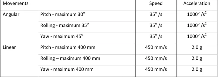
Based on the technical specifications of similar designs, the necessary technical requirements were determined for the adequate operation of the platform, such as the maximum static load (estimated in 150 kg) and limits of movements, according to Table 1 (Reis et. al, 2009).
The feasibility studies would define the option per pneumatic motors or based on electric engines, considering: the initial cost of the components; energy consumption and facility of maintenance of both the systems, whereby all of the parameters offer good advantage to the system based on electric engines, which is corroborated by international producers of small platforms (Reis et. al, 2009).
Movements Speed Acceleration
Pitch -‐ maximum 30o 35o /s 1000o /s2 Rolling -‐ maximum 35o 35o /s 1000o /s2 Angular Yaw -‐ maximum 45o 35o /s 1000o /s2 Pitch -‐ maximum 400 mm 450 mm/s 2.0 g Rolling – maximum 400 mm 450 mm/s 2.0 g Linear Yaw -‐ maximum 400 mm 450 mm/s 2.0 g
It was necessary to integrate six servomotors, connected to a servodrive, which manages them, promoting the interface with the flight simulation software. Servomotors are used in the most diverse industrial applications on elevated dynamics, torque control, and the precision of speed and positioning are necessary requisites. These comprise a servodrive, a programmable processor equipment that commands a servomotor in speed, torque, direction of rotation and axis positioning.
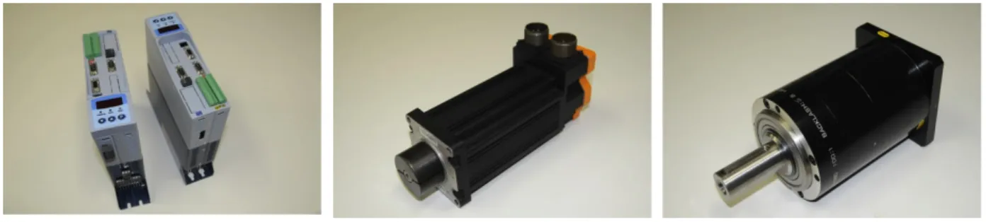
The chosen servodrive for the platform was the model SCA050004T2223POEPZ, Figure 1, and as servomotor the model SWA-‐40-‐2,6-‐30 B5 IP65 230, Figure 2, which has a torque of 2.6 Nm and maximum speed of rotation of 3000 RPM, both devices are marketed by WEG Automação. With the need for higher torque and lower speed, a reducer with a ratio corresponding to 1:100 was also adopted, increasing the torque to 260 Nm and reducing the speed to 30 RPM, i.e. 180o/s, exceeding significantly the speed established as a minimum technical requirement of 35o/s. With this purpose, the equipment selected was the planetary reducer model PE155-‐100, of the industry Apex Dynamics Brasil, Figure 3.
Figure 1. Servodrives. Figure 2. Servomotor. Figure 3. Reducer.
The platform was digitally designed, Figure 4, after defining and acquiring the components of the motor system, based on reverse engineering of the existing platforms. Later on, the robotic platform was built with six degrees of freedom, Figure 5.
Figure 4. Platform: Digital model Figure 5. Platform
3. AUTOMATION
In order to execute the movements of the platform, controlled by computer, a system formed, basically, by a flight simulator (software), a personal computer PC, an electrical interface, and the six interconnected servoconverters SCA-‐05, was projected, Figure 6. Six servomotors complete the system.
Figure 6. Components of the automated system
The basic objective is to allow the control of platform movements via personal computer (master). With this purpose, the physical connection of the servoconverters (slaves) was done initially through a network of RS485 equipment. MODBUS was the data communication protocol chosen, which is popular in industrial applications and has an open code. The speed of communication between the PC controller and the servoconverters was defined as 57,600 Kbps, considering the specifications of the WEG Automation equipment used. The servoconverters have an embedded firmware that allows the transmission control/reception of data by serial interface, that enables the receipt of the data sent by the master (PC), as well as the return of the data it requests.
The Elipse SCADA software (www.elipse.com.br) was used as a high-‐level interface to do the initial validation of the platform movements. Figure 7 allows the visualization of the main screen of the test program developed. It is possible to observe on screen the current position of each axis, as well as define and control the desired movements.
Figure 7. Main screen of the software developed
The first tests of the platform combined altitude and yaw movements. The results were satisfactory and allowed to improve the mechanical system design in order to guarantee better integrity of the platform movements.
To give continuity to the automation project, a dedicated controller was acquired that allows to control of movements with a high communication speed rate (1 Mbps), through a CANOpen interface, replacing the MODBUS network.
Key
Mestre = Master Terminação = Termination Barramento = Busbar
3.1. DEDICATED CONTROLLER
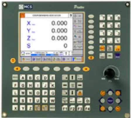
The Proteo CNC controller (MCS Engenharia), chosen as the dedicated interface between the PC and the platform, is based on the Ethernet network, which minimizes wiring and makes its application in large machines flexible. It has a CPU of 32 bits and a color VGA LCD (Liquid Crystal), Figure 8. Proteo allows the generation of positioning trajectories, with synchronized speeds and accelerations through a technique known as interpolation of movements.
Figure 8. Dedicated Proteo CNC Controller
The following steps consist of synchronizing the outputs of the Microsoft Flight Simulator (http://www.microsoft.com/games/flightsimulatorx/) with the platform through the CANOpen communication network managed by CNC Proteo.
4. CONCLUSIONS
Flight simulators reproduce the dynamic model of an aircraft allowing a more realistic interaction between the pilot and simulator. The user, in physical contact with the simulator, experiences real sensations. However, the existing simulators do not consider the strengths related to the efforts of the pilots in actual flights, and conflicting perceptions may cause nauseas. Therefore, the objective of this research is to develop a 6 DOF flight simulator platform to generate movements to promote strengths that are sufficient to prevent contradictory stimulus in the pilot.
This article describes the platform of movements being developed by the Group of Ergonomic Research in Design of UDESC. The platform is still not operational, because for such it depends on the complete implantation of the automation project, already initiated and with preliminary results, as described. However, the results achieved are significant, as the methods put into practice let the first platform movements were performed with success. It is important to note that many of the technological applications involved in the project are unprecedented in Brazil, despite being based on developments for some time practiced in research centers and in international production, so resulting in innovation.
5. ACNOWLEDGEMENTS
This article communicates the partial results of the project "R&D of ergonomic solutions for the design of flight simulators in a virtual reality immersive environment", research maintained by the Department of Design of UDESC, focused on the ergonomic aspects involved in the Technologies of Virtual Reality, funded by CNPq, by FAPESC (Foundation of Support to Scientific and Technological Research of the State of Santa Catarina) and resources from the Research Support Program at UDESC.
6. REFERENCES
[Dasguptaa00] Dasguptaa, B., Mruthyunjayab, T. S. The Stewart platform manipulator: a review. Mechanism and Machine Theory (35), 2000 p.35-‐40.
[Haward10] Haward, D. M. The Sanders Teacher. Flight Vol 2 No. 50 December 10, 1910 p. 1006-‐ 1007.
[Merlet06] Merlet, J. P. Parallel Robots Springer: Holanda, 2006.
[Page09] PAGE, R. L. Brief history of flight simulation. R.L. Page and Associates, (2009).
[Rebelo10] Rebelo, D. R. Automação, Integração de dados e Instrumentação de um Simulador de Vôo. Monografia. Universidade Federal de Minas Gerais. Curso de Graduação em Engenharia de Controle e Automação, (2010).
[Reis09] Reis, Alexandre A. dos., Gomes-‐Ferreira, Marcelo G., Brodbeck, Fábio et. al. Ergonomic Aspects in Virtual Reality Immersive Environment: the design process on Flight Simulators. In: Int. Conf. on Integration of Design, Engineering and Management for Innovation IDEMI'09, 2009, Porto.
[Stewart65] Stewart, D. A platform with 6 degrees of freedom. Proc. of the Institution of mechanical engineers, 180, 1965 (Part 1, 15): 371–386.