INSTITUTO DE INVESTIGAÇÃO E FORMAÇÃO AVANÇADA
ÉVORA, Abril 2016
ORIENTADORES:Professor Doutor Manuel Collares-Pereira Engº João Farinha Mendes
Tese apresentada à Universidade de Évora
para obtenção do Grau de Doutor em Engenharia Mecatrónica e Energia
Especialidade:Energia e Ambiente
Luís Guerreiro
ENERGY OPTIMIZATION OF A
CONCENTRATED SOLAR POWER
PLANT WITH THERMAL STORAGE
i
"You miss 100% of the shots you don't take" - W. Gretzky"Start by doing what's necessary, then do what's possible, and suddenly you are doing the
impossible" - Francisco de Assis
"Fall down seven times, get up eight times" - 七転び八起き
ii
Energy Optimization of a Concentrated Solar Power
plant with Thermal Storage
Abstract
One of the most relevant problems to solve at a planetary scale is the access to an affordable clean source of energy as CO2 equivalent emissions should be reduced significantly. Some
authors aim for a zero emissions target for 2050. Renewable energies will play a leading role in this energy transition, and solar energy with storage is a promising technology exploring a renewable and worldwide available resource.
Within the present thesis component development like a new thermal storage thermocline tank design or having latent heat storage capability are technological developments that have been pursued and analyzed on a system perspective basis, focusing on reducing the LCOE value of a commercial STE plant using TRNSYS software. Material research with molten salts mixtures and cement based materials has been performed at lab scale. A fully validation should occur through a 13 partners pan-European H2020 project called NEWSOL which has been developed supported on the laboratory data obtained.
Moreover, incorporation of local available material, “modern slag” from an old mine of Alentejo region, was also studied. The material could be used as an aggregate incorporated into calcium aluminate cement (CAC) or as filler. This would help to solve a local environmental complex problem related to soil, air and water pollution due to heavy metals and mining activity in Mina de São Domingos, Southeast of Portugal.
The integration of these results underlies a broad energy transition model, a proposal is presented in this thesis, with the aim to foster development towards a sustainable usage of resources and promote clean technologies especially in the energy sector. This model can be locally adapted depending on the pattern of existing industries. The goal is to achieve a smooth transition into a clean tech energy society in line with the target of achieving zero emissions for 2050.
Keywords: Solar Thermal Electricity; Energy Storage; Molten Salts; Cement based mixtures; Thermocline tank design
iii
Optimização
Energética
de
uma
Central
de
Concentração Solar com Armazenamento de Energia
Resumo
Um dos problemas mais relevantes a resolver a uma escala planetária é o acesso, com um custo moderado, a fontes limpas de energia considerando que as emissões equivalentes de CO2 derão ser reduzidas drasticamente. Alguns autores ambicionam mesmo um objetivo de zero emissões em 2050. As energias renováveis irão desempenhar um papel preponderante nesta transição energética, sendo que a energia solar com armazenamento é uma tecnologia promissora que aproveita um recurso renovável e disponível em boa parte do Planeta.
Na presente tese foi realizado o desenvolvimento de componentes nomeadamente o design que um novo tanque do tipo termocline, ou de novos elementos recorrendo ao calor latente, desenvolvimentos tecnológicos que foram analizados de uma perspectiva de sistema, dando o enfoque na redução do custo nivelado da electricidade (LCOE) para uma planta Termosolar usando o software TRNSYS. Foi também realizada investigação em laboratório ao nível dos materiais com várias misturas de sais fundidos inclusivé em contacto directo com materiais de base cimenticia. Uma validação completa deverá ocorrer no projeto NEWSOL do programa H2020 que reúne um consórcio de 13 parceiros europeus e que foi preparado e submetido tendo por base os resultados laboratoriais obtidos.
Adicionalmente, incorporação de material disponível (escória de minério) de uma mina abandonada da região do Alentejo foi outro dos aspectos estudados. Verificou-se que este material poderá ser utilizado como agregado num ligante do tipo cimento de aluminato de cálcio (CAC) ou como “filler”. Este re-aproveitamento resolveria um problema ambiental complexo derivado do elevado conteúdo de metais pesados resultantes da actividade de mineração e que actualamente provocam poluição do solo, água e ar na área da Mina de São Domingos, Sudeste de Portugal.
Estes progressos deverão ser integrados num modelo de transição energética mais amplo. Na presente tese, uma proposta concreta é apresentada, com o objectivo de incentivar o desenvolvimento na direção de uma utilização sustentável dos recursos e a promoção de tecnologias limpas nomeadamente no sector da energia. Este modelo poderá ser adaptado localmente dependendo do padrão de indústrias existente. O objectivo é atingir uma transição suave para uma sociedade de energias limpas em linha com o objectivo de atingir zero emissões de CO2 equivalente em 2050.
Palavras chave: Energia Solar Termoeléctrica; Armazenamento de Energia; Sais Fundidos; Misturas de base cimenticia; Concepção de tanque termocline
iv
Acknowledgements
This thesis is a landmark.
It was a trigger to connect to extraordinary people, to an extraordinary place beyond the Tagus (Alentejo), in a tremendous UNESCO heritage place (Evora) and following the path of megalithic builders who in 4000BC were already looking to the Sun and to the starts (Cromeleque dos Almendres).
The link is the Sun, brought to the Portuguese research community by the inspiring and wide scope knowledgeable Collares Pereira. Supervisor indeed, but much more beyond those borders, a real lighthouse in the landscape using Fresnel lens to concentrate the power of bright minds towards a sustainable development path. My special thanks to him, to Teresa and also to Farinha Mendes, one of the biggest enthusiasts of Solar Energy in Portugal.
A research work as this, is only possible with the support of many important colleagues and friends. For this work to come true, all the Renewable Energy chair members were important with no exemption. My warm regards to all of them specially the pioneers Diogo and João. For the experimental work LNEG (Teresa Diamantino), DLR (Michael Wittmann and Thomas Bauer), CSIC (Maria Alonso), Acciona (José Vera) and ENEA (Walter Gaggioli), all gave a valuable contribution that I am most indebted to. I also thank to the personnel at the UnivEvora, specially to Assunção, Célia and Ana for making things possible in a sometimes diffuse world. Important discussions and contributions also came from João, Sérgio, Ricardo and João, 4 enthusiasts of Solar Energy and its world of underlying possibilities. My Belém friends from ever, from the most Cota, to the least one, I always enjoyed your friendship and always will. I also acknowledge the support of the Portuguese National Science and Technology Foundation, also for supporting key research activities in Portugal like the Research Infrastructure Program, that will give an important contribution to the EMSP – Evora Molten Salt Platform, a bright landmark in Alentejo.
Finally, my most warm affection towards my family, Bruno, Carla, Pa2, Ma2, Du2, they are the reason for this path, its beginning and its end.
v
List of Figures
1.1 Renewable Energy used in Electricity Production in 2013, prediction for 2025 1 1.2 Scenarios for global CO2 eq emissions up to 2050 and 2060 4
1.3 Solar Direct Normal Irradiation Map 6
1.4 Process Applications using Concentrated Solar Power as an Energy source 6 1.5 Energy Storage Technologies, discharge time and power ratings 8
1.6 Project Participation in the period 2011/2015 13
2.1 Heat storage principles: sensible, latent and chemical heat 17
2.2 Sensible heat systems: large seasonal storage 18
2.3 Energy and Power density for batteries 19
2.4 Molten Salts mixtures investigated for STE 21
2.5 Storage Media for STE plants 21
2.6 Durability Model scheme 22
2.4 Molten Salts mixtures investigated for STE 21
2.5 Storage Media for STE plants 21
3.1 LTG scenario BAU versus historical data 1970-2010 24
3.2 Pillar 1: Resource re-distribution 26
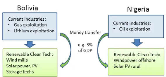
3.3 Pillar 2: funds transferred to clean tech projects, two national examples 27 3.4 Pillar 3: technological MEPS with energy targets 28 3.5 COP standard for heating and cooling applications, Top Runner Program 29
3.6 New CFLR-EM concept 30
3.4 Pillar 3: technological MEPS with energy targets 28
4.1 LFR XX SMS (a) concept (b) ray tracing 34
4.2 IAM Matrix with the optical characterization 34
4.3 Main features of the LFR XX SMS concept 35
4.4 Heat Transfer Media in the temperature range -50ºC to 650ºC 35
4.5 Yearly optical efficiency 37
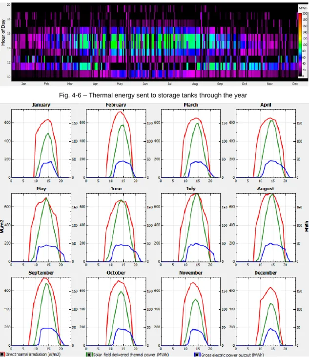
4.6 Thermal energy sent to storage tanks through the year 38 4.7 Yearly available resource, Thermal Power, Net electricity output 38 4.4 Heat Transfer Media in the temperature range -50ºC to 650ºC 35
4.5 Yearly optical efficiency 37
4.6 Thermal energy sent to storage tanks through the year 38
5.1 Test Loop, detail of the Collector field 43
5.2 Test Loop, layout 44
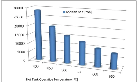
5.3 Storage Volume for different operating temperatures 45 5.4 Main Parameters measured for 8h period on 28/10/2013 46
5.5 DNI data during the test day, 23/09/2013 46
5.6 Energy gain and hourly efficiency 47
5.7 IAM longitudinal for the Parabolic Trough Collect 48
vi
6.1 Solar One, Thermocline Tank (a) vertical section (b) temperature profile 52 6.2 Thermocline Tank, efficiency depending on the ratio diameter to height 53 6.3 Thermocline Tank, new design cross section, with internal baffles 54 6.4 Thermocline Tank with an internal floating barrier 54 6.5 Thermocline Tank using oil as the heat transfer media 54 6.6 1-D simulated thermocline tank cycles (a) charging (b) discharging 55 6.7 HTLT cross section (a), cross section detail (b) 56 6.8 Filler material (a) container (b) aggregates used as filler 576.9 HTLT top view 57
6.10 Monitoring technologies: state of the art and breakthroughs 58 7.1 Overview of solid material selection (a) thermal conductivity, (b) cost 61 7.2 São Domingos mine, (a) Main pit cross section (“iron hat”), (b) Main pit, slag 63
7.4 SEM / XRD Analysis of “modern slag” 65
7.5 CPC type second stage concentrator reactor 66
7.6 Samples selected as filler 67
7.7 DSC Analysis: Filler testing in contact with Molten Salts (500h for 500ºC) 67 7.8 Mix subject to heating cycles (a) compressive (b) flexural strength 68 7.9 Heating cycles (a) mass loss (b) ultrasonic speed 69 7.10 Mechanical resistance (a) compressive (b) flexural 70
8.1 Chemical composition of CAC cement and BFS 74
8.2 Particle size distribution, CAC and BFS 75
8.3 XRD of anhydrous CAC with BFS and SSA aggregate 75
8.4 Bolomey curves for CAC and CAC+ mixtures 76
8.5 Bolomey curves for CAC and CAC+ mixtures 76
8.6 CAC and CAC+ cylindrical samples, in the oven (a), heating cycles (b) 77
8.7 Mass loss after 25, 50 and 75 cycles 78
8.8 XRD (a) and TG/DTA (b) after 1 and 7 days of mortar curing 79 8.9 CAC/CAC+ samples after heat cycles, compressive strength(a) ultra-sound (b) 79 8.10 CAC/CAC+ samples after heat cycles, dynamic elastic modulus 80 8.11 CAC/CAC+ samples, XRD (a) initial and after 25 cycles (b) 25, 50 and 75 cycles 81 8.12 CAC/CAC+ samples (a) cumulative porosity (b) pore volume 82 8.13 Microstructure before heat cycles (up) cement paste (down) oxide composition 83 8.14 Microstructure after heat cycles: (up) cement paste (down) oxide composition 83
vii
8.15 Paste aggregate interfacial zone size depending on aggregate type and size 84 9.1 Compressive strength of a concrete mix tested up to 500ºC and 2250 cycles 88 9.2 CAC+ concrete mix: (a) aggregate (b) CAC+ concrete sample in initial state 89 9.3 Samples CAC and CAC+ set in the oven in direct contact with molten salts 909.4 Samples CAC and CAC+, mass change 91
9.5 Samples CAC and CAC+, Compressive strength and ultra pulse velocity 91
9.6 Samples CAC and CAC+, Pore Diameter 91
9.7 Samples CAC and CAC+, XRD analysis 92
9.8 Samples CAC and CAC+, SEM after 25 cycles in direct contact with MS 92 9.9 Sample CAC+, (a) being prepared for SEM, (b) SEM analysis 93 9.10 Samples CAC+, SEM after 25 cycles (MS filling ITZ cement paste aggregate) 93 9.11 Samples CAC+: SEM Analysis (molten salts initial, 25 cycles, 50 cycles) 94 9.12 Samples CAC+ after MS exposure (initial, 25, 50 cycles): K and Na content 94 9.13 Samples CAC+ after MS exposure (initial, 25, 50 cycles): Si and Fe content 95 9.14 Samples CAC+ after MS exposure (initial, 25, 50 cycles): Al and Ca content 95 9.15 Samples CAC+ after MS exposure (25c.), SEM elemental analysis mapping 96 9.16 Sample CAC (coated and uncoated) after contact with MS, DSC analysis 96
10.1 Project PreFlexMS, activities 101
10.2 Project PreFlexMS, scope of UniEvora 102
10.3 EMSP, detail of the pipping layout in the scope of INNOVLFR 104
10.4 LATENT Concept 107
10.5 SOLSTICE, Concept 109
10.6 SOLSTICE, Activities 111
10.7 SOLSTICE Partners meetings for in depth definition of the work plan 113
10.8 SOLSTICE Organizational structure 113
viii
List of Tables
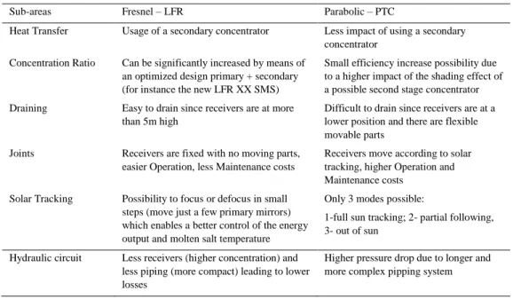
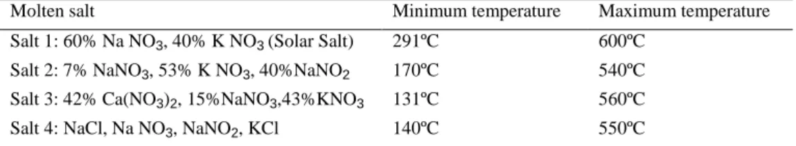
1.1 Publications resulting from work developed in this thesis 11 4.1 Comparison of Fresnel and PTC for usage with molten salts 33 4.2 Maximum and minimum stable operating temperatures for molten salts 35 4.3 Assumptions for the yearly calculation, case: no storage 36
4.4 Main Technical Data 37
4.5 Parametric analysis varying the solar multiple 38
4.6 Economic input data used for Levelized cost of energy (LCOE) calculation 39
4.7 LCOE calculation 39
5.1 Test Loop main characteristics 44
5.2 Merit of the usage of molten salts 44
5.3 Energy Storage for different operating temperatures 45
5.4 Test plan defined 45
7.1 Elemental characterization of the slag in weight 65
7.2 Samples, mix chemical composition 68
7.3 Samples analyzed with different types of aggregates 68
9.1 Concrete mixes comparison 88
9.2 Demonstration Projects 88
9.3 Test Plan 89
10.1 LATENT objectives 107
ix
Nomenclature
TES
E
Total thermal energy storage capacity [Wh]
OUT Cycle,
Cycle efficiency at design conditions [-]
OUT
P
Power output [W]
TES
t
Thermal storage capacity [h]
min , max
,
;
TESTES
Specific volume of the TES medium [g/m
3]
min , max
,
;
TESTES
c
c
Heat capacity of the TES medium [W/g* m
3]
return SF
T
,Return temperature of the solar field medium [◦C]
in SF
T
,Inlet temperature of the solar field medium [◦C]
HE
f
Heat exchanger efficiency factor, solar loop / storage loop [-]
p
c
Specific heat capacity of the molten salts [J/kg*K]
in
T
;
T
outReceiver temperature inlet / outlet [◦C]
loss OPT loss TH gain
E
E
E
;
_;
_Energy: gain / thermal loss / optical loss [kWh]
Ρ
Specific mass [kg/m
3]
ε
Bed porosity
T
Temperature [◦C]
t
Time [s]
Mass flow [kg/s]
A
Bed transversal area [m
2]
H
Volumetric heat transfer coefficient [W/(m
3.K)]
v
Fluid flow velocity (in axial direction) [m/s]
w/c
Water cement ratio [-]
c/s
Cement sand ratio [-]
x
C
Heat-cycle number [-]
E
Dynamic elastic modulus [GPa]
cp
Pulse propagation speed [m/s]
c
Density of concrete [kg/m
3]
Poisson coefficient [-]
Abbreviations
BAU
Business as usual
BAT
Best available technology
BFS
Blast furnace slag
CAC
Calcium aluminate cement mix
CAC+
Calcium aluminate cement mix plus slag
CAES
Compressed air energy storage
CAL
Calcareous based
CAPEX
Capital expenditures
CAT
Calcium aluminate based
CH
Calcium hydroxide
CLFR-EM
Compact linear fresnel reflector concentrator etendue matched
COP
Coefficient of performance
CPV
Concentrated photovoltaics
CSH
Calcium silicates hydrates
CSP
Concentrated solar power
DNI
Direct normal irradiation [kWh/m
2*year]
DSC / TGA
Differential scanning calorimetry / Thermogravimetric analysis
xi
ECV
Electrical car vehicle
EMSP
Evora molten salt platform
FA
Fly ash
GDP
Gross domestic product
GHG
Greenhouse gases
HAZOP
Hazard and operability study
HSM
Heat storage material
HTF
Heat transfer fluid
HTLT
Hybrid thermocline layer tank
IAMT / IAML
Incident angle modifier Transversal / Longitudinal
IEA
International energy agency
IMF
International monetary fund
ITZ
Interfacial transition zone
JCESR
Joint center for energy storage research
LCA
Life cycle assessment
LCOE
Life cycle cost of energy
LPG
Liquefied petroleum gas
LTG
Limits to growth
MS
Molten salts
OECD
Organisation for economic co-operation and development
OPC
Ordinary portland cement mix
OPEX
Operational expenditures
PCM
Phase change materials
PSA
Plataforma Solar de Almeria
PTC
Parabolic trough collectors
xii
SCA
Silicone calcareous composition
SSA
Slag aggregate
SEGS
Solar energy generating systems
SEM / EDS
Scanning electron microscope / Energy dispersive spectroscopy
SF
Silica fume
Si O
Silicious based
SO4
Sulfate
SP
Superplasticizier
SPEC
(Technical) Specifications
STE
Solar thermal electricity
TES
Thermal energy storage
TG / DTA
Thermogravimetric / Differential thermal analysis
USD
United states (of America) dollars
UPV
Ultra pulse velocity
Contents
Abstract. . . ii
Resumo (Abstract in Portuguese). . . iii
Acknowledgments . . . iv
List of Figures . . . ... v
List of Tables. . . viii
Nomenclature . . . ix
Abbreviations . . . x
Chapter 1. Introduction. . . 1
1.1 Motivation 1 1.2 Statement of the Problem, the case for STE- Solar Thermal Electricity with TES 3 1.3 Worldwide Potential for Solar Thermal Electricity 5 1.4 Worldwide Energy Storage Perspectives 7 1.5 Objectives and Methodologies 8 1.6 Structure of the Thesis 10
1.7 Publications 11 1.8 Applied Research. The Renewable Energies Chair of the University of Evora 12 1.9 References 14 Chapter 2. Solar Thermal Electricity and the need for Solar Thermal Energy Storage. . . 15
2.1 Solar Energy 15 2.2 Solar Thermal Electricity 16 2.3 Energy Storage 16 2.3.1 Mechanical Storage 17 2.3.2 Thermal Energy Storage 17
2.3.3 Electrochemical Energy storage 18
2.3.4 Energy storage with Molten Salts 19
2.4 Conclusion 22
Chapter 3. Energy Transition Model. . . .. . . 23
3.1 Transition is inevitable 23
3.2 Simulating the World 23
3.3 Policy Scenarios 25
3.4 The moment for a change is now 25
3.5 Pillars of the Energy transition model 25
3.5.1 Pillar 1: Pricing caps of resource use 26
3.5.2 Pillar 2: Industry transition into Clean Tech 27
3.5.3 Pillar 3: Technological improvements 28
3.5.4 STE as an example 29
3.6 Conclusion 30
3.7 References 31
Chapter 4. Efficiency improvement and potential LCOE reduction, LFR-XX SMS plant. . 33
4.1 Linear Fresnel Systems using molten salts 33
4.1.1 Optical Efficiency Improvement 34
4.1.2 Heat Transfer Media 35
4.2 Yearly Energy Simulation 36
4.2.1 Without Energy Storage 36
4.2.2 Thermal Storage Sizing with Energy Storage 36
4.2.3 Yearly energy yield for Fresnel XX SMS 37
4.3 Economic Valuation 38
4.4 Conclusion 39
4.5 References 40
Chapter 5. Molten Salt Test Loop. . . .. . . 43
5.1 Molten Salt Loop 43
5.2 Test Plan 44
5.2.1 Merit of using Molten Salts 44
5.2 Test Plan 44
5.2.1 Merit of using Molten Salts 44
5.3 Results Discussion 46
5.4 Conclusion 48
5.5 References 49
Chapter 6. Hybrid Thermocline Layer Tank (HTLT). . . 51
6.1 Merit of a Thermocline tank 51
6.2 Historical background 52
6.3 Concept Variants 53
6.4 1-D Tank Modelling 55
6.5 New Tank design 55
6.6 Merit of the HTLT 57
6.7 Conclusion 59
6.8 References 59
Chapter 7. New Materials for Thermal energy Storage. . . 61
7.1 Material Research 61
7.2 Slag, a by-product of mining activity 62
7.3 Environmental issue 63
7.4 Characterization of the Slag, a by-product of mining activity 64
7.5 Valorization scenarios for the slag 65
7.5.1 Extraction of valuable metals 66
7.5.2 Usage in the construction industry 66
7.5.3 Usage as filler material 66
7.5.4 Usage as aggregate material for energy storage 67
7.6 Thermal resistance evaluation 68
7.7 Conclusion 70
7.8 References 71
Chapter 8. Calcium Aluminate Cement for energy storage . . . 73
8.1 Cement for high temperature applications 73
8.2 Experimental Set-up 74
8.2.1 Pre-conditioning and heating protocol 76
8.3 Results and discussion 78
8.3.1 Mass loss 78
8.3.2 CAC stabilization due to BFS addition 78
8.3.3 Thermal fatigue 79
8.3.4 Changes in the microstructure 81
8.3.5 Thermal response 85
8.3.6 Conclusion 85
8.3.7 References 86
Chapter 9. Molten Salts and CAC based cement concrete. . . 87
9.1 Cement based mixtures for Energy Storage 87
9.2 Experimental set-up 88
9.3 Thermal Cycling and Methodology 89
9.4 Results and discussion 90
9.5 Conclusion 97
9.6 References 98
Chapter 10. EMSP Storage upgrade, towards a new set of projects. . . 99
10.1 Introduction 99
10.2 Project HPS-2 99
10.2.1 Challenges and risks 100
10.3 Project PreFlexMS 100
10.3.1 Project goals 100
10.3.2 Activities 101
10.4 Project INNOVLFR 103
10.4.1 New operating strategies 104
10.4.2 EMSP Further Development: Projects LATENT and SOLSTICE 105
10.5 Project LATENT 105
10.5.1 Challenges 106
10.5.2 Working Plan 107
10.6 Project SOLSTICE 108
10.6.2 Project merit 110
10.6.3 Working Plan 111
10.6.4 Project mitigation measures 114
10.7 Conclusion 114
10.8 References 114
Chapter 11. Conclusions. . . 115
11.1 Energy storage is absolutely necessary 115
11.2 Research questions 115
11.3 Thesis Impact 117
11.4 Future Perspectives and lines of investigation 118
11.5 References 118
1
Chapter 1. Introduction
1.1 Motivation
Energy plays a central role in today’s world. Apart from the very basic heating and cooling needs, industrialization has had a big impact on society with machines producing all sorts of goods, a food industry where food is deep frozen and later stored in refrigerators through the whole supply chain, massive daily transportation based on private car usage, long distance passenger transportation based on airplanes and intercontinental freight using large vessels. The growth seen on the transportation sector has been fueled by agreements on free trade, leading to global factories that deploy millions of goods anywhere on the Planet. This has an impact on raw material extraction, on Energy resources with associated negative effects (fossil fuels extraction and burning, CO2 eq. emissions); a fact that many people are not aware of its real dimension and impact, because of the globalized decoupled energy system where coal can be extracted for instance in South Africa, transported by train to a harbor, shipped to the USA, where electricity is produced in a coal fired plant far away from the end user consumption location, who is then very far from feeling the environmental burden of 1 kWh consumed. In addition, depending on the end user appliance there are many cases where more than 90% of the primary energy is wasted in the whole chain of production, delivery and device losses [1]. Energy production has been rising steady, primary energy of 6106 Mtoe in 1973 to 13371 Mtoe in 2012 [2] which corresponded to a total final consumption of 4672 Mtoe in 1973 and 8979 Mtoe in 2012, that is, energy consumption more than doubled in 40 years. Worldwide, in relative terms of fuel share, oil decreased from 48% to 41%, Coal decreased from 14% to 10%, Biofuels and waste constant at 13%, Natural gas increased from 14% to 15%, while electricity has had a significant increase from 9% to 18%.
Electricity as a noble energy form is more and more in use, with a total of 22728TWh generated in 2013. Renewables correspond to 22% of the total generation, already appear with a significant impact in the global mix, the biggest share coming from Hydropower and Windpower. Electricity from renewables is predicted to increase from 5000TWh in 2013 to 7310TWh in 2020 and 10225TWh in 2025. The rise will mainly be achieved with new Windpower, Biomass and Solar Thermal Energy [2].
2
In 2012, worldwide, 28% of Energy was being consumed in the Industry sector, 28% in Transportation sector, 35% in Others (Commercial, Residential, Public Sector, Agriculture, Forestry, Fishing, etc.) and 9% in non-energy usages.In the Industry, energy-intensive sectors, that is, chemicals and petrochemicals, iron and steel, cement, pulp and paper, and aluminium, make up 67% of total industrial energy use. Especially in these industries, process innovation is a key issue. The target [2] is that savings of 4.5 Gton of CO2 eq. emissions (representing 54% of industrial direct emissions) can be achieved in 2050 through: energy efficiency measures, deployment of today’s best available technology (BAT), switching to low-carbon fuel mixes and enhanced material recycling.
In the transportation sector, transitions to alternative liquid or gaseous fuels such as ethanol or hydrogen would require new production, storage, and distribution systems, with major infrastructure new investments that refrain their interest and delay their deployment. In fact, the expansion of the retail infrastructure for alternative fuels may pose greater issues than fuel costs, resources, or production capacity. Thus, a low CAPEX alternative is needed, possible paths include: massive modal shift, increase of occupation rate, changes in passenger behavior and higher renewables incorporation.
It is of major importance to notice, the existence of fossil fuel subsidies, which lead to inefficient use of energy and introduce market distortions, should be phased out as soon as possible. With 550 billion USD in 2013, total fossil fuel subsidies exceeded the subsidies for renewables by a factor of four [3], a fact that usually is not at all highlighted by mass media. A recent study from the IMF reports that if air pollution and associated health problems are accounted, the cost is much higher, estimated to be 5250 billion USD in 2015 [4].
All in all, if all energy subsidies would be removed (namely the ones for drilling exploring activities, gas and oil pipelines, LPG conversion plants), there would be no need to have direct subsidies for Renewables since they would be immediately competitive.
Carbon pricing and removal of fossil fuel subsidies are a necessary measure, but should additionally be complemented with a broader range of policy instruments (e.g. energy standards for buildings, vehicles, electrical appliances; eco-innovation design) to decarbonize the economy at a pace where GHG emissions are effectively reduced in a way to refrain global temperature rise. IEA has defined scenarios for 2050 with 2ºC, 4ªC and 6ºC average temperature increase comparing with 2014 level, that would implicate a shift from current Business as Usual (BAU) moving towards clean tech with a global estimated investment until 2050 ranging from 318 to 358 x1012 USD for the 6ºC and 2ºC scenarios respectively. This investment would represent less than 1% of cumulative GDP and would enable 115 x1012 USD savings in fuel costs [2], thus a transition seems achievable just from an economic resource availability perspective.
3
Furthermore, to decouple economic growth from energy consumption has been a central issue of energy policies and for many the solution that would enable a so called green economy and sustainable consumption patterns. Plenty of scenarios address this issue [5], however historical data shows, that:a) worldwide steady growth of energy consumption in absolute terms has never stopped, b) to be successful with reducing energy absolute consumption, energy intensity levels should decrease more than the double of the historic rate ever registered.
This leads to the central question, in a sustainable society, which variables (GDP output, life expectancy, health and education indicators, leisure time, etc.) are really necessary to growth? Is there a need for continuous economic growth?
Many authors claiming that the Earth has finite resources, state that re-usage, re-cycle is a must and that developed societies need to turn to degrowth strategies and higher efficiency usage, in order to be able to reach long term prosperity respecting the ecological limits, by means of [6].
a) imposing clearly defined resource/emissions caps, b) implementing fiscal reform for sustainability,
c) promoting technology transfer and international ecosystem protection.
To address the above mentioned issues, a new approach towards energy issues is needed, one that fosters R&D, energy efficiency increase, a global model that enables a massive shift towards cleaner/clean energy, together with demand side management introduce incentives towards real energy savings and to closed loops of resource usage. All of this can and must be combined with Renewable energy resources, as these fit the double bill of being clean and inherently sustainable.
1.2 Statement of the Problem, the case for STE- Solar Thermal
Electricity with Thermal Energy Storage
The global problem is the need for a CO2 emission free source of energy if possible at a lower LCOE- Life Cycle Cost of Energy than today’s LCOE mix. From a base level of 32Gton CO2 eq
in 2012, some authors aim for a 0 emissions target for 2050, others are less ambitious in the range 5 to 20 Gt in 2050.
All of them agree that additional major joint efforts need to be performed to avoid BAU expected of 56 Gt in 2050. With the share of electricity gaining relevance, having a 100% renewable electricity production could be a first but very relevant step towards solving the problem.
A significant barrier for large scale deployment of renewable energy is the intermittency of the resource. This can be overcome having storage, a feature that makes Hydropower reservoir dams a valuable asset for managing electricity demand at any given time. The availability of suitable sites for new dams is very limited in Europe and in many parts of the World. From an economic point of view the next available renewable technology with storage in the MW range is Solar Thermal Electricity. It has a very interesting growth potential to produce electricity in a centralized way, since it has a high dispatchability value, is suitable for peak shaving and can
4
have a high capacity factor depending on the solar field and storage sizes.Fig. 1-2 – Scenarios for global CO2 eq emissions up to 2050 and 2060 [5]
For decentralized production with local consumption, typically residential and small businesses, PV and CPV is more adequate since transmission losses are avoided as well as grid capacity costs.
Within the STE-Solar Thermal Electricity area, the technology that has still the greatest technological development ahead and currently has the lowest potential CAPEX/MW installed is Linear Fresnel. Research on optimization of the concept has been pursued in the last 30 years, with interesting applications for STE appearing recently like the CLFR-EM concept [7]. For the current work, this was the base technological concept chosen for further development and system optimization.
Currently, the heat transfer fluid (HTF) used in standard STE plants is thermal oil that starts to degrade at 400ºC, apart from several environmental problems. Additionally there is an indirect system, since molten salts are usually used as storage media. Therefore, there is a clear path for innovation, using molten salts (MS) as the sole media both as heat transfer fluid in the receiver and as storage medium, thus enabling a higher conversion efficiency from the power block. They also have a positive LCA impact on the environment since they are not toxic and can be easily recycled as fertilizers.
From a cost benefit perspective, the established 2 tank MS storage system was developed in the 80s, with several optimization possibilities identified, among them the 1-tank thermocline, a system that deserved special attention in this research.
Moreover, a global problem shall consider solutions that can be adapted locally, solving if possible additional local problems. In current work, waste products from Alentejo (south of Portugal) region were analyzed, in order to find a solution to re-cycle or re-use them, in order to improve local sustainability within resource usage.
Finally, sustainability of resource usage associated with energy supply should have a global and integrated approach; during the development of the present thesis it became evident the need for a broad model that could become a framework to enhance and accelerate the necessary
5
energy transition (the so called Energie Wende in german).In order to come up with solutions for the above named research issues, several research questions (RQ) were formulated and addressed:
RQ1: Can a new STE plant concept be optimized to achieve a lower LCOE than current LCOEmix for the south of Europe?
RQ2: Which could be the heat transfer fluid and storage media of such a plant?
RQ3: What progress is needed in terms of material science development and validation to enable new storage concepts for STE applications?
RQ4: What type of local materials could be used thinking on resource sustainability and closed loop systems?
RQ5: How could such concepts be validated taking advantage of the existing Evora Molten Salt
Platform (EMSP) facility in order to enable a fast technological deployment?
RQ6: How could a transition to an integrated sustainable global energy system take place, and which energy policies could be implemented?
1.3 Worldwide Potential for Solar Thermal Electricity
All renewable forms of energy have a direct or indirect link to the Sun. From a useful energy point of view, there are some minor effects, induced gravity ones due to its mass, others resulting, for instance, from its magnetic field, but very large and main ones come from solar radiation that heats the Earth, inducing thermal currents of different fluids and temperature gradients that shape the Earth’s climate. Solar collectors used for hot water production transfer the energy received to the fluid used, mainly constituted by water.
High concentration of solar energy however, uses direct solar radiation (DNI) since the solar beam will be focused into a receiver tube with a Concentration factor (~25 x or more), so that, much more energy can be delivered per m2, and thus higher temperatures in the range 250-600ºC can be obtained using adequate heat transfer fluids.
STE plants will then convert direct normal radiation into electricity, the higher the resource, the higher the yearly energy production for a certain location and for the same investment cost. Thus, choosing a prime location is a major issue. Currently, as a rule of thumb it is considered that at least 1800 - 2000 kWh/m2 a year of beam radiation are needed in order for a STE plant to be economically competitive, the best sites being the ones that receive more than 2800 kWh/m2 a year like in northern Chile where LCOE can be 35% lower than in the south of Spain [8]. The majority of the regions suitable are located in the tropics, namely the North American “sunbelt” area, north of Africa, Middle East, Tibet, Australia, Southern part of Africa and northern part of Chile, as it can be seen in Fig.1-2, on the basis of satellite. Most of these areas are desert areas with very low availability of water, which makes STE ideal to be integrated with desalination plants. It should be noted, that for locations where potable water is a high valuable resource, using STE plants to focus primarily on potable water is an in indirect way of storage.
6
Fig. 1-3 – Solar Direct Normal Irradiation Map [9]From a baseline of 4 GW of STE worldwide capacity in 2014, IEA estimates STE could have an installed capacity between 1000GW and 1500GW in 2050, only in Saudi Arabia 25GW are envisioned to be deployed until 2032. Other authors are event more ambitious, of 8000GW [10] of installed solar (PV+STE) capacity worldwide in 2050.
Land area for STE plants is usually not a problem, since locations where solar resource is the highest tend normally be arid or desert regions. It should be highlighted, that for instance in USA, a square of 153*153 km in the sun belt region (Arizona, Nevada, California) with state of the art STE would be enough to deliver all electricity needs in USA. [11]
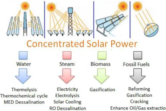
Fig. 1-4 – Process Applications using Concentrated Solar Power as an Energy source
Apart from producing electricity via thermal (STE), concentrated solar power is a highly interesting R&D topic since it can be used for several other applications when coupled with water, steam, biomass and fossil fuels, Fig.1-4. An interesting example is oil and gas enhanced
7
extraction by means of introducing solar generated steam in the reservoirs to increase its pressure in order to further extract fossil fuels. A demonstration Project in Oman shows that both from a technical and cost perspective for this application it makes more sense to use solar energy than the also locally available gas [12]. Many other interesting applications can be thought of, including processes that need temperatures above 1000ºC, a feature possible today with focal point systems.1.4 Worldwide Energy Storage Perspectives
Energy storage is a key issue on a dynamic energy system where supply permanently has to meet the oscillations of a variable demand load. For mobility purposes, most vehicles use fossil fuels (gasoline, diesel, LPG, av-jet, etc.) that come from refineries by pipeline or lorries, are stored in gas stations, and later on as chemical energy in the tank of cars, boats, trains and airplanes. This fossil fuel network with large storage facilities (for raw material 90 days consumption is the usual stock) was a large investment made in the past in most OECD countries.
Energy storage technologies available for large-scale applications can be divided into four types: mechanical, electrical, chemical, and electrochemical.
With the “electrification” trend in the industry, transportation and heating (e.g. heat pumps) sectors, for efficient grid management, storage that can be integrated into the electricity grid is becoming an important asset. Reverse-pumped hydropower accounts for 99% of the worldwide storage capacity of 127 GW of discharge power, and Compressed air storage (CAES) comes with 0,44 GW in a distant second place. These two technologies dominate in the MW range. In Europe, 10% of the total electric power delivered uses some form of energy storage, in Japan 15%, while in USA only 2,5% [13]. The trend is showing a clear need for additional storage in order to give stability to the grid, enable peak shaving and stabilize energy acquisition costs. Electrochemical storage shall play a more relevant role in the future, going along the growth in sectors like residential PV and ECV broader usage. In this field several technologies are competing, both from a cycle charge/discharge efficiency as well as cost. Current energy density for Li-ion batteries are ca. 250Wh/kg, with a forecasted increase up to 400Wh/kg. Solutions with Lithium and air batteries could achieve up to 1000Wh/kg, however major technical constraints seem difficult to by-pass. Other solutions at a lower cost like Na-O2, might
become an interesting alternative.
For Windpower parks, CAES has been studied and some projects have been implemented, however only seldom is a geological site available with suitable location nearby, making it difficult to become a mainstream solution.
For STE, 90% of the commercial plants that have storage use molten salts, up to now a binary mixture of 60%NaNO2 and 40% KNO2 is the current standard, however ternary and quaternary mixtures which have been formulated and validated at lab scale, may present an alternative for the future, especially if the whole system is optimized and a lower LCOE is achieved.
8
Fig. 1-5 – Energy Storage Technologies, discharge time and power ratings [13]1.5 Objectives and Methodologies
A general objective of this Thesis is to find ways (technologies, operation guidelines, fast market deployment) to increase the attractiveness of STE technology, to make it an interesting and even a natural choice in many parts of the world where solar energy is abundant. To achieve that aim, several objectives have been pursued:
1st main objective: Designing a new STE plant with a lower LCOE
To make STE more competitive against other technological options, LCOE should decrease by means of technical component improvement as well as an overall new plant design/concept. As a starting point, the Fresnel concept was selected due to the potentially lower CAPEX/MWe and for its good potential of performance increase.
Methodology: Several technical features have been studied namely:
Optical optimization of the primary mirrors, starting from the LFR basic concept (a topic pursued by another researcher [7] ) at the University of Evora (RE Chair)
Optical optimization of the secondary mirrors, developing new concepts as the CLFR-EM and SMS XX (a topic pursued by another researcher) [7]
Increase of the operating temperature validating the usage of molten salts up to 565ºC Develop operating strategies for the usage of molten salts as a HTF in a Fresnel type
collector
These technical features have been simulated and evaluated using specific simulation software (ray tracing and TRNSYS), in order to predict the energy output, capacity factor and overall plant efficiency. Meteonorm weather data for Faro-PT and Hurgadha-EGP was used. For the techno-economic evaluation, SAM interface by NREL was used, to calculate the LCOE value.
9
2nd main objective: Storage material developmentExisting heat storage material (HSM) were analyzed. Considering the requirements for the material thermo-physical characteristics, a short list of alternative materials was elaborated. It became clear that to increase the concept sustainability, usage of local materials should be considered as part of the storage mix concept.
Methodology: HSM literature review, followed by an analysis of local suitable material that could be used as part of the overall concept. Selected materials included several molten salt mixtures and solid material (rocks). A binder was developed to create a new material that would be in contact with molten salts. The materials selected went through a process of testing simulating thermal cycles in the range 290-550ºC, and finally, from the experimental work, several techniques were used to characterize the findings, namely:
Compressive strength Ultra pulse velocity Microscopy SEM/EDS XRD analysis
Chemical analysis DSC and TGA
Mass loss and mass change
Thermal conductivity, diffusivity, heat capacity
3rd main objective: Incorporation of local materials to solve an environmental problem
Renewable energy should be supported by a strong commitment of preserving local resources (clean air, water, raw material), in order to become both a global solution and to have a significant local impact. For this reason local available materials that could be used as a HSM were analyzed, namely materials that had no longer an economic value, which could become a twofold advantage. On one hand re-using a material no longer needed and, besides, with a substantial contamination potential and, on the other hand when the acquisition cost is zero (or, even belter, when there is a price a price to pay for environmental impact) it would contribute towards the LCOE reduction objective. In Alentejo, south of Portugal, there are several quarries which have produced a significant amount of residues (on average 70% of the material extracted) as well as mine residues from former extraction of Copper, Gold, Zinc, Sulphur. In the Alentejo region, south of Portugal, cartography of old mine sites and quarries was studied specially in the Iberian Pyrite belt geological zone, which included visits and sample collection to several of them (Lousal, Canal Caveira, São Domingos, Beringel). After a first analysis it became clear, that the most severe environmental problem of all locations was in São Domingos, a mine that was closed in 1966 leaving behind several million ton of residues in an extension of more than 10km polluted soil and water streams, and thus the material selected for deeper analysis was a local abundant residue identified as “modern slag”.
Methodology: samples from three different locations within the São Domingos area were collected. All of them corresponded to “modern slag”, however dumped at a different time and
10
place. These samples were then separated according to its grain size, and different incorporation rates were tested, in order to use it as an aggregate of a new mixture using a CAC base cement. Cylindrical samples were casted and put in contact with molten salts for thermal cycles in the range 290-550ºC. To characterize the mixture, several techniques were used, namely: Microscopy SEM/EDS Chemical analysis
Thermal conductivity, diffusivity, heat capacity Crack analysis
4th main objective: Development of a scalable concept with fast deployment into the market A new concept is more relevant, as it is scalable and easy to be implemented globally. That focus was there from an early stage, which led to a modular concept, where capacity can be easily increased with time and CAPEX can be divided into several years. A broader energy transition model was also developed, where technological improvements like the ones dealt in this work, are just a small part of a bigger and global framework.
Methodology: Discussion with industry partners about which solutions could be implemented on a real power plant, and what steps would be needed for a fast technology deployment. With this aim, a consortium was put together, with all necessary expertise in order to develop an extensive project with the aim of validating the new storage concept.
1.6 Structure of the Thesis
The work developed in this thesis is organized in the following way:
Chapter 1, Introduction: describes the motivation that led to the development of this work, stating the problem as well as the research questions dealt with.
Chapter 2, State of the Art: A technical review concerning STE technology and energy storage is performed, identifying the main technological constraints and current innovation areas. Chapter 3, Energy Transition Model: The energy transition model is explained with its different mechanisms, as well as giving application examples
Chapter 4, Fresnel SMS XX Plant Simulation: A new plant Fresnel type with optimized optics, Molten Salts as HTF is simulated using TRNSYS/SAM considering storage and two locations Chapter 5, Molten Salt loop validation: Experimental values (temperature, flow, pressure) are analyzed from a research campaign performed at an R&D Parabolic Through loop
Chapter 6, New storage concept: A new thermocline tank concept (HTLT) is presented to be coupled to STE plants using direct Molten salts both as HTF and HSM
Chapter 7, Material development - slag incorporation: The reasoning and technical background for the incorporation of old mining residues from Alentejo region is discussed
Chapter 8, Material development - new cement based mix: New mix development and tests performed is presented, based on cement CAC type with and without the incorporation of slag
11
Chapter 9, Material development - new mix in contact with Molten Salts: Tests performed using the new mix in direct contact with molten salts are presentedChapter 10, EMSP loop development: Projects (HPS-2, PreFlexMS, INNOVLFR, LATENT, STOREMAT,) related to foreseen future developments of the EMSP site are presented
Chapter 11, Conclusions: Overall achievements and answers to the research questions are presented, as well as an outlook of future research topics
For the above work to be possible, many contributions were highly valuable, namely the ones enabling experimental work relevant for the content of different chapters. Therefore, I shall acknowledge and express my gratitude to following entities and persons for the meaningful discussions and support provided throughout this thesis: LNEG (T.Diamantino, A.Vieira, J.Cardoso, R.Tarouca, S.Casimiro, P.Azevedo), UniEvora (D.Canavarro, J.Marchã, A.Correia), DLR (M.Wittmann, M.Grünefeld, T.Bauer), ENEA (W.Gaggoili, A.Primo), CSIC (M.Alonso), ETH (A.Steinfeld, R.Castro), SENER (J.Burgaleta), SINTEF (H.Justnes), YARA (E.Iglesias, W.Franke), ACCIONA (J.Vera).
1.7 Publications
The work developed along the chapters in this thesis resulted in a number of publications which included conference presentations, journal and policy papers, as well as several R&D projects and patent application, all summarized in the following table.
Table. T1-1 – Publications resulting from work developed in this thesis
Chapter Paper Title Published in / status
2 XII Storage Technologies challenges and opportunities for CSP In preparation*
3 V Resources and Energy LTG Whitepaper LTG Proceedings 2013
3 XIII Energy Transfer Model, a new global energy framework beyond 2020
In preparation*
3 IX Energy and Environmental reform in EU – path after 2020, a Policy Paper to ALDE
ELF 2015, ALDE
Congress, Nov.2015
4 I Increasing cost effectiveness of CSP technologies through the development of a new CLFR “etendue matched” collector
ISES Proceedings 2011
4 II Increasing the efficiency of conventional LFR Technologies: A new CLFR “Etendue Matched” CSP collector
Solar Paces Proceedings 2011
4 III Modeling Thermal Losses in a new CLFR-EM non-evacuated collector cavity
Solar Paces Proceedings 2011
4 IV Energy storage for CSP plants, overview and detailed discussion of a storage system for a new Fresnel Plant
INNOSTOCK Proceedings 2012
4 VII Efficiency improvement and potential LCOE reduction with an LFR-XX SMS plant with storage
Energy Procedia 2015 – Vol. 69, p.868-878
5 VI Energy output and thermal losses in a PTC molten salt test loop Solar Paces Proceedings 2014
6 XIV The Hybrid Thermocline Layer Tank (HTLT): A novel concept to improve Thermocline type tanks
In preparation*
6 Patent
ap.
Hybrid Thermocline type tank w/ well defined solid and fluid layers
12
6 Patent
ap.
Thermal Storage with hybrid sensible and latent heat modular units (encapsulated PCM type)
submitted to INPI, 2015
7 X New Materials for thermal energy storage in Concentrated Solar Power plants
Energy Procedia 2016 – Vol. 88
8 VIII Calcium aluminate based cement for concrete to be used as thermal energy storage in solar thermal electricity plants
Cement and Concrete Research, vol.82, p.74-86
9 XI Energy Storage for Solar Thermal Electricity using Molten salts and Calcium aluminate based cement concretes
submitted to Solar Energy, 2015
10 Projects HPS-2, PreFlexMS, INNOVLFR, LATENT, SOLSTICE submitted to BMWi and H2020, 2015
NB: * Papers XII-XIV in preparation, include research performed during PhD period
1.8 Applied Research. The Renewable Energies Chair of the
University of Evora – a comment on the background support
An essential part of work done in more fundamental research, is to produce bright ideas and concepts that can be further pursued and developed to a stage that companies find attractive enough to invest in their commercial application. All work done at the Renewable Energies Chair of the University of Evora aims at achieving that broad goal.
From the start the Chair understood the need to create the proper R&D infrastructure to be able to carry out work in the solar Concentration area.
Essential to the motivation for the work done in this thesis, is an important part of the Chair’s plan, the Evora Molten Salt Platform (EMSP) located 10km south of Evora, belonging to the University and aiming at becoming a reference research facility in Europe, for Solar Thermal Electricity and thermal energy storage technologies. Currently the framework of a trans European cooperation in this area is being discussed in the EU-Solaris platform.
In order to enhance the value and research capability of the EMSP, the Renewable Energies Chair with the important help of the work described in this thesis, has defined, organized, and submitted several projects to the relevant financing institutions. Some of them involve as many as 15 partner institutions among universities, companies and research laboratories, meaning there is a broad team that needs to be coordinated and research aims harmonized. These projects are part of an expansion plan for the EMSP and its capabilities, in order to make it a world class research facility and a worldwide reference within Solar Energy. In Fig.1-6, the participation and own contribution in the projects elaborated is described. The author would like to express its gratitude for all the Partners involved in the different projects, for their professionalism and commitment, specially to DLR, ACCIONA, CSIC, LNEG and ETH, who made it possible for such big challenges to become a reality.
As a final and important note, while the work in this thesis was being carried out, the Chair managed to establish very important R&D agreements with top R&D institutions like DLR (D-Köln) and Fraunhofer ISE (D-Freiburg) and created a National Research Infrastructure for Solar Energy Concentration, INIESC, in collaboration with LNEG-Laboratorio Nacional de Engenharia
13
Fig. 1-6 – Project Participation in the period 2011/201514
1.9 References
[1] Lovins, A., Energy End-Use Efficiency, Rocky Mountain Institut, 2005 [2] IEA, Energy Technology Perspectives, 2015
[3] IEA, World Energy Outlook, 2014
[4] IMF, “How Large Are Global Energy Subsidies?”, IMF Working Paper, 2015
[5] Loftus, P. "A critical review of global decarbonization scenarios: what do they tell us about feasibility?" WIREs Clim Change 6:93–112, 2015
[6] Jackson, T. “Prosperity without growth? Economics of a Finite Planet”, Earthscan Pub., 2014 [7] Canavarro, D. “Advances in the design of Solar concentrators for Thermal applications”, PhD Thesis, 2015
[8] IDB, Chile, Concentrated Solar Power Project, 2013
[9] Trieb, F. "Global Potential of Concentrating Solar Power", Solar Paces 2009 [10] WWF-World Wildlife Fund. Climate Solutions: WWF’s Vision for 2050; 2007
[11] Mills, D. “Solar thermal electricity as the primary replacement for coal and oil in USA Generation and transportation”, 2009
[12] Bierman, B. "Performance of an enclosed trough EOR system in South Oman", Solar Paces 2013
[13] Dunn, B. "Electrical Energy Storage for the Grid: A Battery of Choices” Science 334, 928, 2011
15
Chapter 2. Solar Thermal Electricity and the need for
Solar Thermal Energy Storage
2.1 Solar Energy
Energy consumption more than doubled in the last 40 years, from all renewable energy sources solar energy has the highest potential do deliver energy both in the form of heat (heating or cooling systems) or in the form of electricity. Worldwide solar photovoltaic (PV) capacity grew by an estimated 40 GWp in 2014, slightly more than the previous year. Growth was strong in China (10 GWp) and Japan (9 GWp), with Asia alone responsible for 50% of the new solar PV capacity. United States accounted for 6.5 GWp installed, in Europe leading markets were Germany (2GWp) and UK also with 2GWp installed [1], capacity installed in Europe was 39GWp at the end of 2011 [2]. This progress is explained by a number of reasons: falling prices of PV systems (60% reduction in the last 5 years), feed-in programmes in several countries to foster initial market development, technological improvements.
On PV, the leading technology in making solar cells is crystalline silicon due to its high efficiency, which reaches 20% or higher in the case of mono-crystalline cells developed using the Czochralski process. However, due to cost reasons, researchers focus on reducing material costs using thin film technology (amorphous, CIS/CIGS, CdS/CdTe), since it uses less material and the layers are much thinner compared to mono- and polycrystalline solar cell thus lowering the manufacturing cost. In lab scale the best thin film technology achieved as much as 19%, silicon crystalline 25% and multi-junction cells with 236x concentration factor as high as 40%. Using Fresnel lens, concentrating the solar radiation in photovoltaic cells (CPV) is a way to reduce the amount of silicon while delivering more energy per area.
Solar heat has also been growing in Europe, however at a more moderate pace. In 2014, EU27 had 28GWth installed, representing 40 million m2 of solar thermal collectors mostly in small size systems up to 10kWth. District solar heating systems represent just 12% and are most used in counties like Denmark and Germany. Solar collectors have seen also interesting developments in recent years, like the Compound Parabolic Concentrator (CPC) collector, the evacuated tube collector, polymeric collectors with new features like transparent insulation and selective glazing.
Another promising field is Solar Thermal Electricity (STE), which has the advantage of being a dispatchable way of producing electricity since it can have storage facilities (being molten salts the most used media) for several hours of operation with very low losses in the storage system.
16
2.2 Solar Thermal Electricity
Parabolic trough technology is the dominant (>90% market share) solar thermal technology for power generation, that has proven long term (>30 years) commercial references since 1984 with the parabolic trough power plants commissioned in the USA, the SEGS plants of Krammer Junction and Harper Lake in California. These power plants were operating successfully from the beginning and were optimized to a high level within years. After a long period where there were no new commercial plants, since 2008 also new parabolic trough power plants have been put in operation (i.e. Andasol I-III, Alvarado I), specially in Spain because of a set of stable conditions that enabled long term planning and investment. Other technologies like Linear Fresnel or Central Receiver (tower) concepts were not as much developed on a commercial scale mainly because of nonscientific/technical reasons, i.e reasons connected with the capacity to get the right financing on the market, taking advantage of the past experience (Luz projects in the US, in the late eighties and nineties) and the reputation of reliability already associated with them. The situation is slowly changing and a larger percentage of the most recent projects use these other technologies.
At present several other solar thermal power plants are in the planning, design or construction phase, in markets as Morocco, South Africa, UAE or USA. From a historical and experience reason most concepts focus on thermo-oil as heat transfer fluid in the solar field. The maximum working temperature of the thermo-oil (usually VP-1) is limited to 395°C due to the thermal stability of the oil, which starts to degrade at that temperature. Therefore the live steam temperature is limited to about 375°C so that at a steam pressure of 104 bar a net efficiency of about 37% can be achieved in the power block.
In contrast to most other players the Italian industry has focused its research activity on the concept of molten salt as heat transfer and storage medium. Experiences from the “Solar Two” tower project built in the 80’s in Dagget, California in which this concept was technically demonstrated between 1996 and 1999 at a 10 MW scale have shown a certain vulnerability to technical failure but also indicate solutions on how problems can be solved. In 2011, a consortium with the name Gemasolar started to operate a technically revised follow-up plant (19MWe electric power, 16h energy storage, 3 times larger solar field than Solar Two) using Solar Salt as the heat transfer. In 2012, a 5MWe parabolic through plant was developed in Priolo Gargalo, Italy coupled to an existing combined cycle plant. In 2013, an Italian/Japanese consortitum inaugurated a molten salt test loop in Massa Martana, Italy, where new receivers specially for molten salt will be investigated and further developed. In 2015, the design of a test loop using Fresnel collectors and molten salts as a heat transfer medium is being planned in USA by Sandia, confirming the broad interest that molten salt technology is achieving.
2.3 Energy storage
Energy storage emerges as an obvious need, to enable a more dependable energy delivery from an energy source that varies during the day / night cycle, with season, and with the local climates and their random impacts on the available sunshine.
17
In particular for the topics addressed in this thesis related to the production of Solar Thermal Electricity, Energy Storage emerges as a very powerful way of generating true dispatchability in conjunction with solar thermal systems, at a potentially low cost. In this respect it creates an advantage (rather a true complementarity) when compared with PV (photovoltaic) today. There is a wide variety of Energy Storage systems. Generally can be dived into the following categories: Mechanical storage systems (e.g. compressed air); Thermal storage systems (e.g. ice storage); Electrochemical storage systems (e.g. batteries); Chemical storage systems (e.g. hydrogen);
Magnetic storage systems (e.g. superconducting magnetic); Biological storage systems (e.g. glycogen);
2.3.1 Mechanical storage
Energy storage using compressed air CAES is a well established technology, the first utility-scale project in Huntorf, Germany started in 1978. It is a 321MW plant which takes 8 hours to charge. The energy stored allows its generators to run at full capacity for 2 hours. At peak hours the air is drawn out and combusted with natural gas before passing through a turbine to generate power. The plant reports a cycle efficiency of 42%. In USA, McIntosh, Alabama there is a similar plant with 110MW capacity and an efficiency of 54%. At both plants compressed air is stored in existing underground salt caverns, which is a very limiting fact for further deployment of this technology. Nevertheless in the USA, there have been built several installations coupled to wind power sites.
2.3.2 Thermal Energy storage
For solar energy systems, the most used technology is thermal energy storage. This can be done in three different ways: sensible, latent heat (phase change) and thermo-chemical storage. Sensible heat storage, supplying heat to a fluid or a solid which is then well insulated is the most used, however, research is being performed in order to achieve a more compact way of storing energy.
Sensible Latent Chemical
Volume 120 60 12 m3
Density 110 250 500-3000 MJ / m
3
31 70 140-830 kWh / m3
Fig. 2-1 – Heat storage principles: sensible, latent and chemical heat with typical volume and density The specific application is depending on the functionality namely the following criteria:
![Fig. 1-2 – Scenarios for global CO2 eq emissions up to 2050 and 2060 [5]](https://thumb-eu.123doks.com/thumbv2/123dok_br/15473848.1035266/22.892.210.686.134.444/fig-scenarios-global-co-eq-emissions.webp)
![Fig. 1-5 – Energy Storage Technologies, discharge time and power ratings [13]](https://thumb-eu.123doks.com/thumbv2/123dok_br/15473848.1035266/26.892.187.711.113.473/fig-energy-storage-technologies-discharge-time-power-ratings.webp)
![Fig. 2-3 – Energy and Power density for batteries [4]](https://thumb-eu.123doks.com/thumbv2/123dok_br/15473848.1035266/37.892.181.715.110.428/fig-energy-and-power-density-for-batteries.webp)
![Fig. 3-5 –COP standard for heating and cooling applications, Top Runner Program [7]](https://thumb-eu.123doks.com/thumbv2/123dok_br/15473848.1035266/47.892.202.714.126.436/fig-cop-standard-heating-cooling-applications-runner-program.webp)