Polytechnic of Leiria
School of Technology and Management
Department of Electrical and Electronics Engineering Master in Electrical and Electronic Engineering – Electronics and
Telecommunications D I S S E RTAT I O N E L E C T R O N I C A L LY R E C O N F I G U R A B L E F S S - I N S P I R E D T R A N S M I TA R R AY F O R T W O D I M E N S I O N A L B E A M S T E E R I N G F O R 5 G A N D R A D A R A P P L I C AT I O N S AT 2 8 G H Z
mário antónio patrício carreira vala
Polytechnic of Leiria
School of Technology and Management
Department of Electrical and Electronics Engineering Master in Electrical and Electronic Engineering – Electronics and
Telecommunications D I S S E RTAT I O N E L E C T R O N I C A L LY R E C O N F I G U R A B L E F S S - I N S P I R E D T R A N S M I TA R R AY F O R T W O D I M E N S I O N A L B E A M S T E E R I N G F O R 5 G A N D R A D A R A P P L I C AT I O N S AT 2 8 G H Z
mário antónio patrício carreira vala Number: 2172276
Dissertation supervised by Professor Rafael F. S. Caldeirinha
([email protected])and Doctor João R. Reis ([email protected]).
A C K N O W L E D G M E N T S
I would first like to thank my supervisors, Professor Rafael Caldeirinha and Doctor João Reis for the continuous guidance and assistance throughout this work, that allowed me to fulfill the objectives and achievements defined for this dissertation.
I would also like to thank the School of Technology and Management of Polytechnic of Leiria and the Instituto de Telecomunicações - Leiria (IT-Leiria), for granting me access to the laboratory facilities and radio equipment necessary for the completeness of this dissertation and, in particular, to project RETIOT (SAICT-45-2015-03 / Projeto nº 16432) for funding my research developments. I would also like to thank IT-Aveiro, particularly Professors João Nuno Matos and Pedro Cabral for allowing me to use some of their equipment and for helping me with some of the measurements needed to validate the developed prototype.
I would like to acknowledge my colleagues at IT-Leiria Antennas and Propagation group, especially André Sardo and Wilson Conniott for their support and willingness to help me when I most needed.
In addition, I would like to thank my parents and sister for their continuous support and for encouraging me to always continue forward and never give up. Lastly, a big thank you to my girlfriend for always staying by my side and supporting me even when things didn’t go as planned.
A B S T R A C T
In this dissertation, the author’s work on a 28 GHz transmitarray capable of antenna beamsteering for various wireless applications, is presented. Such device allows for the adjustment of the radiation pattern of an antenna by changing its main lobe direction, without the need of any mechanical means.
A unit-cell based on a square-slot Frequency Selective Surface (FSS) is designed, simulated and optimised through several full-wave simulations, using an electromag-netic solver (CST MWS). Subsequently, the unit-cell was extended to a 10x10 array configuration in order to enable Two-dimensional (2D) beamsteering. This work yielded the fabrication of a prototype composed of four passive transmitarray lens, which were experimentally tested and characterised. Finally, a novel unit-cell based on a double square-slot intended aiming at active beamsteering was also studied and optimised in simulation environment.
From this work, it was demonstrated that transmitarray can be seen as feasible alternative to many traditional beamsteering techniques, such as phased antenna arrays, while reducing the RF burden of the overall system using only a single radiation source. This fact, allied with it’s ease of integration, reduced cost and low-profile characteristics make transmitarrays a desirable solution for 5G and RADAR applications, among others.
Keywords: Transmitarray, Beamsteering, Frequency Selective Surfaces (FSS), 5G.
TA B L E O F C O N T E N T S
Acknowledgments i
Abstract iii
Table of Contents v
List of Figures vii
List of Tables xi
List of Acronyms xiii
1 introduction 1
1.1 Background study and Motivation . . . 1
1.2 Objectives . . . 2
1.3 Dissertation layout . . . 3
2 literature review 5 2.1 Introduction . . . 5
2.2 Transmitarray for antenna beamsteering . . . 7
2.2.1 Reconfigurable based on microstrip patches . . . 8
2.2.2 Reconfigurable based on tunable metamaterials . . . 11
2.2.3 Reconfigurable based on FSS . . . 15
2.3 Transmitarray for polarisation control . . . 22
2.4 Hybrid Transmitarray . . . 25
2.5 Interim conclusions . . . 33
3 beamsteering with a transmitarray 35 3.1 Introduction . . . 35
3.2 Theoretical model for1D–beamsteering . . . 35
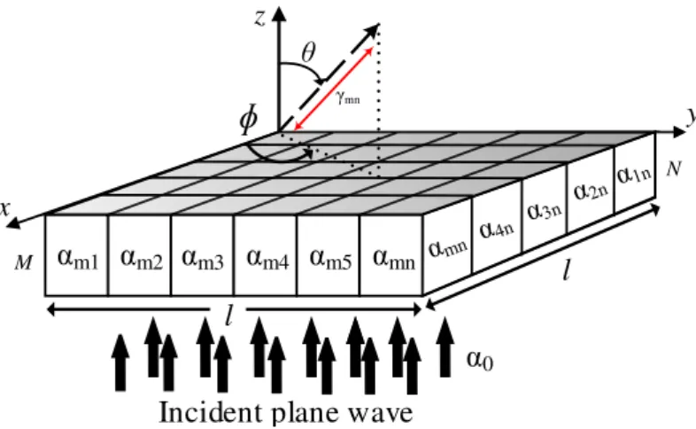
3.3 Theoretical model for2D–beamsteering . . . 36
3.4 Interim conclusions . . . 39
4 design of a passive transmitarray 41 4.1 Introduction . . . 41
4.2 Stacked unit cell . . . 41
4.3 Full structure simulation and beamsteering evaluation . . . 48
4.4 Output angle compensation . . . 50
4.5 Interim conclusions . . . 52
5 optimisation, prototyping and characterisation of a passive transmitarray 53 5.1 Introduction . . . 53
5.2 Optimisation of the 10 × 10 transmitarray . . . . 54
table of contents
5.2.2 Capacitors real value effects on beamsteering . . . 56
5.2.3 Capacitors tolerance effects on beamsteering . . . 58
5.3 Measurement setup . . . 59
5.4 Experimental results and analysis . . . 63
5.5 Interim conclusions . . . 70
6 development of an active transmitarray 71 6.1 Introduction . . . 71
6.2 Practical limitations . . . 72
6.2.1 Impact on unit-cell frequency response . . . 72
6.2.2 Impact of parasitics on Beamsteering with transmitarray . . . 76
6.3 Design of a novel dual-polarised unit-cell . . . 78
6.3.1 Initial design . . . 78 6.3.2 Improved design . . . 81 6.4 Interim conclusions . . . 86 7 conclusions 87 7.1 Introduction . . . 87 7.2 Dissertation Review . . . 87
7.3 Contributions to the knowledge . . . 88
7.4 Future work . . . 89
bibliography 91
L I S T O F F I G U R E S
Figure 2.1 Generic model of (a) a transmitarray and (b) a reflectarray antenna. . . 7 Figure 2.2 (a) Reconfigurable element (exploded-view) and (b)
respec-tive transmitarray prototype (images extracted from the work presented in [41]). . . 9 Figure 2.3 (a) Unit-cell design and (b) transmitarray prototype for
antenna beamsteering (images extracted from the work pre-sented in [44] and [46], respectively). . . 10 Figure 2.4 (a) Schematic view of the 2-bit unit-cell and (b) simulated
radiation pattern for two angles (images extracted from the work presented in [47]). . . 11 Figure 2.5 (a) Unit-cell design and (b) top view of assembled 6x6
trans-mitarray prototype (images extracted from the work pre-sented in [48]). . . 12 Figure 2.6 Prototype of a single opened fishnet unit-cell layer (images
extracted from the work presented in [16]). . . 13 Figure 2.7 Metamaterial unit-cells for transmitarray antennas presented
by (a) Yongzhi S. et. al. and by (b) Jiang T. et. al. (images extracted from the work presented in [49] and [50], respectively). 14 Figure 2.8 (a) Prototype of theMMbeamsteering antenna and (b)
mea-sured radiation pattern for different steering angles (images extracted from the work presented in [50]). . . 14 Figure 2.9 (a) FSS transmitarray model and (b) respective unit-cell
prototype evaluated using the waveguide method (images extracted from the work presented in [53] and [54], respec-tively). . . 16 Figure 2.10 (a) 6 × 6 transmitarray prototype, (b,c) measured radiation
pattern in azimuth and elevation planes, respectively (images extracted from the work presented in [55]). . . 17 Figure 2.11 (a)FSS transmitarray model and (b) respective
transmitar-ray prototype (images extracted from the work presented in [56]). . . 18 Figure 2.12 (a) Unit-cell model, (b,c) 5 × 5 transmitarray prototype and
(d,e) measured radiation pattern for (15◦,15◦) and (25◦,25◦), respectively. (images extracted from [58]). . . 20
list of figures
Figure 2.13 (a) Measured radiation power for each setup from 3 to 7 GHz, (b) measured radiation pattern for each setup from −60◦ to 60◦ at 5.2 GHz and, (c) measured radiation pattern for the smart wall tuned to 0◦, 10◦, 20◦ and 30◦. . . . 21 Figure 2.14 Geometry of transmitarray unit-cell (image extracted from
the work presented in [59]). . . 22 Figure 2.15 (a) Patch unit-cell and (b) transmitarray model for
polar-isation control (images extracted from the work presented in [65]). . . 23 Figure 2.16 (a) Transmitarray unit-cell architecture and (b) photography
of the unit-cell prototype (images extracted from the work presented in [75]). . . 25 Figure 2.17 Transmitarray unit-cell architecture (image extracted from
the work presented in [78]). . . 26 Figure 2.18 (a) Transmitarray unit-cell design loaded with p-i-n diodes;
S21 amplitude and phase response for: (b,c) simulated and (d,e) experimental results, respectively. (images extracted from the work presented in [79]). . . 28 Figure 2.19 Snapshot of (a) the active unit-cell and (b) transmitarray
for beamsteering and polarisation control (images extracted from the work presented in [81]). . . 29 Figure 2.20 (a) Geometry of the transmitarray element and (b)
recon-figurable transmitarray prototype with 16 × 16 elements (images extracted from the work presented in [82]). . . 30 Figure 2.21 (a) Antenna prototype and (b) measured realized gain for
several beamsteering angles between 0◦ and 50◦ (images extracted from the work presented in [83]). . . 31 Figure 3.1 (a) Model of linear antenna array and (b) model of a
trans-mitarray for 1Dbeamsteering analysis. . . 35 Figure 3.2 Proposed model for a transmitarray with 2Dbeamsteering. . 37 Figure 3.3 Axial representation of the (a) spherical coordinate system
(θ/φ) and (b) Azimuth-over-Elevation coordinate system Az,El. . . . 39 Figure 4.1 (a) Square slot FSS unit cell and (b) unit cells equivalent
circuit. . . 42 Figure 4.2 Dependency of (a) total phase shift and (b) S21 with the
variation of number of layers for 1pF, considering Case 1. . . 43 Figure 4.3 Dependency of (a) total phase shift and (b) S21 with the
list of figures
Figure 4.4 Dependency of S21with value of capacitance for unit-stacked cell with 7 layers, considering (a) Case 1 and (b) Case 2. . . 47 Figure 4.5 5x5x7 full transmitarray. . . 48 Figure 4.6 Simulated 3D radiation patterns considering (Az,El): (a)
(16◦,0◦) and (b) (-18◦,13◦). . . 49 Figure 4.7 Phase matching model best fit for both (a) azimuth and (b)
elevation planes. . . 50 Figure 4.8 Optimised simulated3Dradiation patterns considering (Az,El):
(a) (16◦,0◦) and (b) (-18◦,13◦). . . . 52 Figure 5.1 Simulated 3D radiation pattern for: (a) Prototype 1, (b)
Prototype 2, (c) Prototype 3 and (d) Prototype 4, considering high resolution for capacitance values. . . 55 Figure 5.2 Simulated 3D radiation pattern for: (a) Prototype 1, (b)
Prototype 2, (c) Prototype 3 and (d) Prototype 4, considering rounded capacitance values. . . 57 Figure 5.3 Simulated 3D radiation pattern for Prototype 2
consider-ing: (a) maximum tolerance and (b) random tolerance for capacitance values. . . 58 Figure 5.4 Simulated 3D radiation pattern for Prototype 3
consider-ing: (a) maximum tolerance and (b) random tolerance for capacitance values. . . 59 Figure 5.5 Photograph of the transmitarray prototypes. . . 59 Figure 5.6 S11 measurement setup. . . 60 Figure 5.7 Frequency response setup measurement using spectrum
anal-yser. . . 60 Figure 5.8 S21and radiation pattern measurement: (a) diagram and (b)
anechoic chamber setup. . . 61 Figure 5.9 Comparison between simulated and measured S11 for: (a)
Free space, (b) Prototype 1, (c) Prototype 2, (d) Prototype 3 and (e) Prototype 4. . . 64 Figure 5.10 Simulated S11: (a) without and (b) with solder mask. . . 65 Figure 5.11 Measured received power for: (a) Free space, (b) Prototype
1, (c) Prototype 2, (d) Prototype 3 and (e) Prototype 4 for frequencies in the range of 23 to 29 GHz and azimuthal angle between −40◦ and 40◦. . . . 66 Figure 5.12 Measured received power for: (a) Free space, (b) Prototype
1, (c) Prototype 2, (d) Prototype 3 and (e) Prototype 4 for frequencies in the range of 23 to 29 GHz at 0◦. . . . . 68 Figure 5.13 Measured azimuthal radiation patterns for: (a) Free space,
list of figures
Figure 6.1 (a) Ideal capacitor and (b) varactor diode models. . . 71 Figure 6.2 Effects of (a) series inductance and (b) series resistance on
S21 for unit-cell at 28 GHz. . . 73 Figure 6.3 Comparison of total achieved phase for different values of
series inductance. . . 73 Figure 6.4 Effects of (a) series inductance and (b) series resistance on
S21 for unit-cell at 5.5 GHz. . . 74 Figure 6.5 Simulation results when considering series resistance and
series inductance, simultaneously: (a) S21 and (b) achieved phase shift. . . 76 Figure 6.6 Total beamsteering range depending on the maximum phase
shift obtained by the unit-cell. . . 77 Figure 6.7 Simulated radiation pattern for 5x5x7 transmitarray
consid-ering (a) capacitor ideal model at 28 GHz and (b) complex model with series inductance (0.2 nH) and resistance (2 Ω) at 25 GHz. . . 78 Figure 6.8 Double slot unit-cell. . . 79 Figure 6.9 Frequency response of the double slot unit-cell. . . 79 Figure 6.10 Phase shift of the double slot unit-cell depending on
capaci-tance value. . . 80 Figure 6.11 E-field orientation: (a) vertical and (b) horizontal. . . 81 Figure 6.12 Simulated radiation pattern for a 5 x 5 transmitarray with
steering angle (Az,El) = (10◦,10◦) considering (a) vertical polarisation and (b) horizontal polarisation at 27.8 GHz. . . 82 Figure 6.13 Simulated radiation pattern for a 5 x 5 transmitarray
consid-ering (a) vertical polarisation and (b) horizontal polarisation at 27.8 GHz. . . 83 Figure 6.14 Improved double slot unit-cell. . . 83 Figure 6.15 Frequency response of the improved double slot unit-cell (a)
S21 and (b) maximum phase shift achieved. . . 84 Figure 6.16 Simulated radiation pattern at 28.2 GHz considering: (a)
vertical polarisation steering to (16◦,−21◦) and (b) horizontal polarisation steering to (−10◦,0◦). . . . . 84 Figure 6.17 Simulated radiation pattern at 28.2 GHz considering: (a)
ver-tical polarisation steering to (−25◦,−25◦) and (b) horizontal polarisation steering to (25◦,25◦). . . 85
L I S T O F TA B L E S
Table 2.1 Summary table of references for polarisation control (Pol.)
and beamsteering (BS) transmitarrays . . . 32
Table 4.1 Unit cell dimensions . . . 42
Table 4.2 Parametric study on number and distance between layers for a substrate with thickness 0.254 mm. . . 44
Table 4.3 Parametric study on number and distance between layers for a substrate with thickness 0.635 mm. . . 45
Table 4.4 Parametric study on number and distance between layers for a substrate with thickness 0.762 mm. . . 46
Table 4.5 Simulated beamsteering output angles . . . 50
Table 4.6 Expected vs simulated beamsteering angles. . . 51
Table 4.7 Beamsteering results for phase compensation. . . 51
Table 5.1 Beamsteering output angles for the 10 × 10 transmitarray considering high resolution for capacitance values. . . 56
Table 5.2 Beamsteering output angles for the 10 × 10 transmitarray considering rounded capacitance values. . . 58
Table 5.3 Parameters for reference measurement system at 25 GHz . . 63
Table 6.1 Comparison of parasitic effects at 28 and 5.5 GHz. . . 75
Table 6.2 Parasitics for different varactor diodes. . . 75
Table 6.3 Maximum steering angles for different series inductance val-ues considering a 5x5 transmitarray. . . 77
Table 6.4 Dimensions of the double slot unit-cell . . . 79
L I S T O F A C R O N Y M S
1D One-Dimensional. 2D Two-Dimensional. 3D Three-Dimensional.
BST Barium-strontium-titanate. CST Computer Simulation Technology. DC Direct Current.
EM Electromagnetic.
FSS Frequency Selective Surfaces. GPIB General Purpose Interface Bus. LHCP Left-hand Circular Polarization. MEMS Micro Electromechanical Systems. MM Metamaterials.
MWS Microwave Studio. PCB Printed Circuit Board. PLL Phase Lock Loop.
RADAR Radio Detection And Ranging. RF Radio Frequency.
RHCP Right-hand Circular Polarization.
Rx Receiver.
SMD Surface Mount Devices. SMT Surface Mount Technology. SNR Signal-to-Noise Ratio. TA Transmitarray.
Tx Transmitter. UC Unit-cell.
1
I N T R O D U C T I O N1.1 background study and motivation
Electronic beamsteering is a concept that has gained huge interest in last years since it allows for the directing of the antenna beam towards a desired direction without the need for mechanical equipment. The most common method to perform beamsteering is by using phased antenna array [1–3]. An antenna array consist of a physical distribution of several antenna radiation elements, in the same plane, forming different patterns and configurations. By applying the correct phase difference between adjacent cells, it is possible to control the direction of the outgoing wave (or incoming wave when set for receiving mode), and thus perform beamsteering. However, the need for a different phase shifter for each of the cells proved to be costly and turned the system rather complex, which led to the search for new alternatives.
One of the favoured solutions that started to appear as a possible alternative to phased antenna arrays are transmitarrays. Transmitarrays are devices typically placed over a directional antenna aperture with the aim of altering its radiation properties, e.g. to perform focus, beamsteering or beamforming. Following the same physical principal of the phased antenna array, transmitarrays are often comprised of several similar unit-cells in which both frequency and phase response (phase-shift) depends on the unit-cell physical dimensions, and/or by loading discrete components such as capacitors, varactors or p-i-n diodes.
Depending on the the unit-cell design and on the discrete components employed in its composition, transmitarray can be used as passive device, e.g. as fixed beam lens aiming towards a specific direction, or as a reconfigurable (active) capable of adjusting the direction of the beam electronically.
In fact, electronic beamsteering using transmitarrays is both timely and topical in the context of the 5th generation of mobile network (5G) [4] and Radio Detection And Ranging (RADAR)applications, particularly when these are applied to single radiating directive sources, such as a horn antenna. In the last years, several transmitarrays have been presented for 5G operating frequencies at sub-6 GHz band and at 28 GHz
introduction
1.2 objectives
To this extent, this research work aims at the development of aFrequency Selective Surfaces (FSS)-inspired transmitarray for antenna beamsteering, for 5G andRADAR applications, at 28 GHz. This is sought to build upon the work carried out at 5 GHz [5]. Beamsteering using transmitarrays aims to eliminate the need of phase shifters by using artificial structured materials inspired on, for example, Metamaterials (MM)[6,7] andFSS[8–11]. These structures exhibit resonant characteristics based on the appearance and geometries of the unit-cells. Furthermore, when using p-i-n or varactor diodes, it is possible to to modify the the capacitance value of the LC equivalent circuit of the unit-cell allowing for the control and tuning of the frequency response.
In this way, transmitarrays with such characteristics allow for an electronic control over beamsteering, overcoming the limitations imposed by the traditional array systems regarding the burden ofRadio Frequency (RF)circuitry. This feature, when allied to the inexpensivePrinted Circuit Board (PCB)manufacturing costs allow to a reduction of overall weight, power consumption and dimensions of the system, making these structures very attractive for inclusion in a large number of 5G and RADARapplications.
The main key objectives of this work are as follows:
• Review of the transmitarrays with beamsteering and polarisation control capabilities present in literature;
• Study of the theoretical models forOne-Dimensional (1D)andTwo-Dimensional (2D)beamsteering using a transmitarray;
• Familiarization with a full wave Electromagnetic (EM) solver (Computer Simulation Technology (CST) Microwave Studio (MWS));
• Dimensioning and characterisation of unit-cell based on FSS for passive transmitarray, using discrete capacitors in simulation environment;
• Prototyping and implementation of a passive transmitarray using the previ-ously characterised unit-cell experimental tests of the passive prototypes;
• Study of the influence of the parasitic elements of the varactor diodes on the frequency response of the unit-cell and overall transmitarray capabilities;
• Dissemination of the work being performed in several conferences and journal publications with relevant scientific reputation.
1.3 dissertation layout
1.3 dissertation layout
Having the objectives in consideration, this dissertation is structured as follows:
Chapter2presents an extensive literature review and critical analysis on the topic of transmitarrays. Transmitarray based on different approaches and unit-cells (based on microstrip patches, MMandFSS) and employing p-i-n or varactor diodes,Micro Electromechanical Systems (MEMS) switches or even liquid crystals, are presented. Transmitarrays are divided in three categories: polarisation control, beamsteering and hybrids (transmitarrays that allow both polarisation control and beamsteering).
Chapter3 presents the theoretical background for antenna beamsteering using a transmitarray. Both 1D and2D beamsteering model approaches are presented herein.
Chapter 4describes the methodology and characterisation of a passive transmi-tarray with two-dimensional beamsteering capabilities at 28 GHz. Firstly, several parametric studies in simulation environment are presented in order to ascertain the best dimensions for the unit-cell that allow better beamsteering results. Finally, a 5 × 5 array model composed of the designed unit-cells was characterised in terms of beamsteering performance.
Chapter 5 provides details on the practical implementation of the previously presented transmitarray, as well as additional simulations that were needed during the prototyping phase. In this chapter, the measurement setups and result analysis are presented.
Chapter6describes the simulation study carried on the unit-cell and, consequently, on the transmitarray, when the discrete capacitors considered previously are replaced by a more realistic model of the varactor diode. Two new unit-cells are then presented in order to perform beamsteering even when considering the parasitics of the varactor.
Chapter7is dedicated to the conclusions and final remarks of the work. Consider-ation is given regarding the topics that require further investigConsider-ation as an extension of the work presented in this dissertation. Finally, the major contributions to the scientific community and knowledge are reported.
2
L I T E R AT U R E R E V I E W2.1 introduction
Antenna beamsteering is a very useful and desirable technique in any wireless communication system since it allow to dynamically adjust the antenna pattern and consequently enhance Signal-to-Noise Ratio (SNR) [1]. Such feature is crucial to some applications that require tracking of objects and adaptation to dynamic scenarios with multipath and moving scatterers, e.g. base-station dynamic antenna alignment, wireless back-haul links auto-alignment due to pole swaying and twisting in the wind or mobile user tracking. Since such antenna systems is focusing their energy toward the receiver, it is increasing the useful received signal level and, thus, lowering the interference level. Hence, higher Signal-to-inference Ratio increases the capacity of the system and improves range and the coverage area.
The most traditional manner of implementing beamsteering is by using arrays of antenna [1–3]. However, the well known design limitations particularly regarding to the feeding network implementation, led to the introduction of alternative techniques to perform beamsteering. In 1986, McGrath firstly introduced in his paper [12] a microwave lens with focusing and scanning capabilities, by simply connecting two microstrip patch antennas using vias in both sides of a planar structure, forming a spatial array of microstrip patches, i.e. a transmitarray. Since then, transmitarray has been seen as a feasible alternative to phased antenna arrays and the focus of novel and extensive research nowadays.
Transmitarray [13–15] is the conventional name given to structures that can modify the original radiation pattern of a directional antenna source, e.g. horn antenna, when placed at a distance sufficiently away from its aperture. To the set composed by the structure and the radiating source, it is referred as transmitarray antenna [13–15]. Due to their electromagnetic properties, such structures are capable of modifying the characteristics of the incidentEMwave emitted by the source, and perform beamsteering, focusing or even polarisation control, by re-transmission of the incident EMwave. Thus, one can imagine a transmitarray acting, in a sense, like a lens, allowing to pass-through the incident wave with an alteration (or not) of its direction of propagation, as depicted in Fig.2.1a. The direction to which the incident wave is being re-radiated depends on the design of the structure. These
literature review
structures are commonly composed by several resonant unitary elements (unit-cells) with a spatial periodicity forming a planar array [13–15]. The unit-cells are typically based on simple microstrip patches, or inspired byMM[6,7] and FSS[8–11]. From a practical point of view, since transmitarray structures are mostly implemented using PCB technology [13–15], by etching the unit-cell geometries on a copper covered substrate, they benefit from being planar and thus easy to integrate with other radio peripherals. Furthermore, they are compatible with Surface Mount Technology (SMT) allowing to reduce the size of assemblies, and finally, since they have the electromagnetic feeding source separated from the beamsteering network, they offer higher degree of modularity to the system as opposed to traditional antenna array. Thus due to their design simplicity and, more importantly, due to the low manufacture costs, they have been extensively utilized for numerous antenna applications.
In order to achieve reconfigurability and enable features, such as electronic beamsteering, polarisation control or frequency tuning, transmitarray are typically enhanced by using p-i-n diodes, varactor diodes,RFor MEMSswitches or manufac-tured using tunable substrates as liquid crystal or graphene. However, each of these methods present advantages and disadvantages, e.g. p-i-n and varactor diodes are widely utilized in transmitarray designs from lowRFto around 30 GHz, mostly due to their size, easy integration inPCBand low cost. However, they are limited when operating at high frequencies (above 30 GHz), with insertion loss proportional to the frequency of operation that arise from their intrinsic parasitic parameters (series resistance, capacitance and inductance).RF andMEMS switches are typically more expensive than p-i-n/ varactors and prone to failure over time, due to the wear and tear of the mechanical parts. Alternatively, tunable dielectric materials, i.e. materi-als that can have their electromagnetic properties (in particular ǫr) manipulated by an external stimulus (bias or voltage), such as liquid crystal and graphene are also employed for transmitarray implementations [16–22]. Furthermore, while liquid crystal technology have been successfully employed in transmitarray designs [16], it is more commonly used in reflectarray implementations [23–26] or as grounded substrate for conventional microstrip antennas [27–29]. Graphene substrates, on the other hand, are typically used at THz frequencies due to their unique electronic properties as reported in [30], even though applications in antennas design at micro-and millimeter-wave frequencies, have already been reported in [31].
The research on transmitarray has always been paired to the one on reflectarray [32,33]. Reflectarray, which operating principle is depicted in Fig. 2.1b, makes use of the reflection principle (based on Snell’s law [32,33]) to modify the properties of the re-transmitted EM wave. In fact, the most significant difference between a transmitarray and reflectarray is that, in the latter, all power is re-radiated independent on the frequency or cell design. If the unit-cells are not matched to the
2.2 transmitarray for antenna beamsteering Source Transmitarray structure Incident wave Re-trans mited wave ϕ1 ϕ1 ϕ2 ϕ2 ϕ3 ϕ3 ... ... ϕn ϕn (a) Source Reflectarray structure Incident wave Re-trans mited wave ϕ1 ϕ1 ϕ2 ϕ2 ϕ3 ϕ3 ... ... ϕn ϕn (b)
Figure 2.1: Generic model of (a) a transmitarray and (b) a reflectarray antenna.
frequency of operation, the elements will have small effect on the array response and the reflecting ground plane will predominate. In the worst case scenario, the reflected wave could have the same direction of the original one [32,33]. On the other hand, for a transmitarray, if the structure is not well matched to the free-space or if the unit-cells are not adapted to the frequency of operation, the incident EMwave will be totally reflected back, resulting in no transmission through the structure [13,14]. Therefore, a transmitarray is desirable to be the most "transparent" as possible, introducing very low loss so the EMfield of the propagating wave is not severely attenuated, whereas the reflectarray is desirable to be a perfect reflecting surface so the incident wave can be entirely reflected.
However, although reflectarray have been successfully implemented in [15,32–38], the feed blockage remains a challenge in implementation of such type of devices since the feeding source is on the same side of the radiated field. This may be a challenging depending on the final application that can be overcome with the use of a transmitarray.
2.2 transmitarray for antenna beamsteering
Several examples can be found in the literature for transmitarray aiming antenna beamsteering. They comprise the use of different materials, unit-cells designs and implementation approaches. However, there is one requirement that must be satisfied to use such structures to steer the main beam of an antenna radiation pattern. The unitary element that composes the transmitarray must have transmission phase that can be varied (tunable) up to 360◦ (as will be explained in section3.3), while the transmission magnitude (desirably) remains constant over the bandwidth,. Therefore, this section is focused on the review of transmitarray structures and unit-cell elements, with reconfigurable capabilities that enable electronic beamsteering.
literature review
2.2.1 Reconfigurable based on microstrip patches
Particularly in [39], a reconfigurable transmitarray for beamsteering is proposed. The device is composed of a set of patch antennas placed on each side of the array structure and connected by an electronically tunable phase-shifter, where the innovation of the work relies on. The phase-shifter is developed in transmission line technology and consists of a microstrip directional coupler terminated with reflective LC circuits, whose capacitance (C) is controlled by a varactor diode. Consequently, by tuning the value of C, it is possible to selected whether the terminations of the coupler are open- or short- circuit and thus, control the phase-shift between the input and the output of the transmitarray. Nevertheless, this solution turned out to be limited in terms of phase range and since several couplers are cascaded together to overcome this issue, the size and complexity of the phase-shift network is consequently increased. This forced a large separation between the radiating elements, that were arranged in groups of 4 elements and separated by 1.4 wavelengths, leading to the reduction in the scan capability and to the appearing of grating lobes. Therefore, a maximum of 9◦ of angular shift is reported on the azimuth plane. The proposed solution presents 700 MHz of bandwidth and 3 dB of insertion losses but such values are advertised for the phase-shifter alone and not for the complete transmitarray.
Remarkably in their work, Lau and Hum [13,40–43] have introduced several models of active unit-cells and of electronically controlled transmitarray. Specifically aiming antenna beamsteering, it is presented and characterized in [40] and further improved in [41] a transmitarray element (Fig.2.2a) that consists of two microstrip patches on either side of a ground plane coupled to a small slot aperture. Each patch is split in half with a small gap in between, and varactor diodes inserted to connect the two halves, while another varactor diode is inserted at the center of the slot, connecting the two sides of the slot. Together, all these parts act as three coupled tunable resonators that provides a variable phase-shift over 360◦ with 3 dB of insertion losses, as reported in [41]. However, the losses are slightly increased to 4.8 dB (over the same bandwidth), when the proposed element is composing a 6 × 6 array and the biasing network to control the varactors are included, as depicted in Fig.2.2b [41]. Nonetheless, the developed prototype achieved ±25◦ of electronically controlled beam scanning, in azimuth and elevation planes independently, with a broadside directivity of 20.8 dBi.
As alternative, a different unitary element is proposed and characterized by the same authors in [42]. The unit-cell for transmitarray applications explores the properties of proximity-coupled feeding and aperture coupling [1]. In this solution, the array element is implemented with microstrip patches in both sides of the
2.2 transmitarray for antenna beamsteering
(a) (b)
Figure 2.2: (a) Reconfigurable element (exploded-view) and (b) respective transmitarray
prototype (images extracted from the work presented in [41]).
structure separated by a ground plane. Each patch fed a differential microstrip transmission line by mutual coupling. In one of the sides, possess a differential bridged-T phase-shifter composed by varactor diodes and Direct Current (DC) blocking capacitors. Both sides of the structure are further interconnected also by aperture coupling through two open slots etched in the ground plane. According to experiments realized on a single unit-cell using the waveguide method, which consists of a sample of the unit-cell enclosed between two waveguide flanges, it is notably achieved a tunable phase range of around 425◦ and insertion loss in average of 3.4 dB at 4.86 GHz. This model is however limited by the narrow bandwidth of the radiating elements and such drawback is mitigated, on a final prototype by employing a stack of microstrip patches. The final array element exhibits insertion losses of around 3.6 dB with a phase range over 400◦, but the bandwidth was increased from 100 to 500 MHz at the same central frequency. Subsequently, a 6 × 6 reconfigurable transmitarray composed of active elements of [42] is finally presented and evaluated in terms of beamsteering performance in [43]. The prototype of the transmitarray provides a scanning range of ±50◦ in both elevation and azimuth planes, with 2.2 dB of insertion losses and 10% bandwidth (500 MHz) at 5 GHz.
Moreover, in [44], a novel unit-cell design is proposed and characterised for an electronic control of the wave direction using a transmitarray. It is composed of a passive microstrip patch antenna with U-shape slot etched on the reception plane, and an active patch with an etched O-shape slot in the re-transmission plane, as depicted in Fig.2.3a. The active O-shape is loaded with two p-i-n diodes (and in an alternative design with RF- MEMS) that allow to control the transmission phase by alternatively activating diode states. A 15% of bandwidth and around 3 dB of insertion losses at 10 GHz are reported experimentally on a single unit-cell, evaluated using the waveguide method also employed in [42]. Later in [45], the same unit-cell
literature review
(a)
(b)
Figure 2.3: (a) Unit-cell design and (b) transmitarray prototype for antenna beamsteering
(images extracted from the work presented in [44] and [46], respectively).
design using MEMS presents a bandwidth of 16% but 4 dB of insertions losses. In [46] the authors presented a full characterization of a 20 × 20 transmitarray comprising 800 p-i-n diodes and the respective feeding mesh. The prototype is depicted in Fig.2.3b. The authors state that the proposed transmitarray exhibits a 2D beamsteering capability with maximum ranges of ±40◦ in elevation and ±70◦ in azimuth.
Another unit-cell for beamsteering transmitarray at Ka-band based on p-i-n diodes is presented in [47]. The paper starts by characterising by simulations an novel unit-cell design. In particular, this novel unit-cell design allows for a 2-bit phase resolution and has an overall size of 5.1 × 5.1 × 1.3mm3 (λ/2 × λ/2 × λ/8 at 29 GHz). The unit-cell is composed of six metal layers printed on three substrates as shown in Fig.2.4b, of which the ones at the edges are O-slot rectangular patch antennas loaded with two p-i-n diodes for phase control. Similar to other cases already presented [44,46], the p-i-n diodes in each of the antennas are biased in opposite states (one p-i-n diode is ON while the other is OFF). By choosing which diode is ON at a given time, a 180◦ phase-shift is achieved. Therefore, by combining the different states of the receiving and transmitting layers, a total of four phase.shifts can be achieved (0◦, 90◦, 180◦ and 270◦). The presented unit-cell is used to implement a 14 × 14 element transmitarray in simulation environment whose beamsteering range is reported up to −40◦, as shown in Fig.2.4b.
2.2 transmitarray for antenna beamsteering
(a) (b)
Figure 2.4: (a) Schematic view of the 2-bit unit-cell and (b) simulated radiation pattern
for two angles (images extracted from the work presented in [47]).
More recently, in [48] a new unit-cell for a beamsteering transmitarray is presented. Each cell is comprised of four stacked Rogers RO4350B double sided layer, as depicted in Fig. 2.5a. Since one pair of layers (sub-element) can only achieve 180◦, this arrangement has to be replicated in order to achieve the desired 360◦ of phase shift. Varactor diodes are used in every layer to control, electronically, the element phase-shift. Although the paper reports a bandwidth of 1 GHz for the unit-cell at 24.6 GHz, this value is defined by the frequency range in which the phase-shift is above 360 degrees, and not from the S11/S22 filtering response as normally characterized in this type of work. This unit-cell, exhibits then a total insertion loss of around -5 dB obtained in simulation and -12 dB obtained experimentally. Finally in [48] a 6 × 6 transmitarray composed of the aforementioned unit-cell has been built (Fig. 2.5b). This transmitarray is able to steer the main beam direction up to ±50◦ in both the azimuth and elevation planes, at 24.6 GHz, with a maximum attenuation of 17 dB at the extremes of the steering interval.
2.2.2 Reconfigurable based on tunable metamaterials
Transmitarray composed ofMMto perform antenna beamsteering are also reported in the literature. Metamaterials are artificial man-made structured materials able to produce electromagnetic properties (permittivity, permeability and refractive index) which are unusual or non-existent in nature [6,7] and such properties can be explored for transmitarray designs.
literature review
(a)
(b)
Figure 2.5: (a) Unit-cell design and (b) top view of assembled 6x6 transmitarray prototype
2.2 transmitarray for antenna beamsteering
Figure 2.6: Prototype of a single opened fishnet unit-cell layer (images extracted from the
work presented in [16]).
It is the case of the work described in [16], [49] and [50], where1D beamsteering, i.e. main lobe limited to steering in a single plane, is demonstrated using such type of materials. These works [16,49,50] suggest new steerable antennas by using controllableMM(electronically reconfigurable) to form the transmitarray. Although implemented with different resonant unit-cell designs, they all respect the same physical principle: tunable refractive index structures are utilized to electronically control the direction of the outcoming wave. The steering is achieved when the refractive index of the MM structure is tuned, leading to a progressive phase distribution along the structure, acting as a linear phased array.
For example, in [16] the authors have developed and characterized an artificial gradient-index metamaterial by designing a fishnet structure on a liquid crystal sub-strate. The transmitarray was practical validated against measurements conducted at 27.5 GHz. A beamsteering angular range limited to ±5◦ was achieved by varying, in a gradient manner, the bias of each array column. According to the authors, the yielded angular range can be enhanced by staking more layers of the one depicted in Fig. 2.6.
In [49] and [50], the authors have followed an alternative approach to design their transmitarray. Both presented structures are composed of staked layers of periodically printed sub-wavelength metallic resonators with embedded microwave varactors. By adjusting the varactor diode, the resonant characteristics of the unit-cell is modified controlling, in fact, the associated phase-delay between the first and the last layer of the transmitarray. Consequently, the associated effective refractive index of a single transmitarray element is being adjusted. Accordingly, if a progressive phase between adjacent elements is applied through the array in order to perform beamsteering, the metamaterial exhibits a gradient index of refraction, when seen as an whole.
Therefore in [49], 6 stacked layers of a double-layer I-shaped unit-cell (Fig.2.7a) are suggested as array element, exhibiting 360◦ of phase-shift at 1.6 GHz while the
literature review
(a) (b)
Figure 2.7: Metamaterial unit-cells for transmitarray antennas presented by (a) Yongzhi S.
et. al. and by (b) Jiang T. et. al. (images extracted from the work presented
in [49] and [50], respectively).
(a) (b)
Figure 2.8: (a) Prototype of theMMbeamsteering antenna and (b) measured radiation pattern for different steering angles (images extracted from the work presented
in [50]).
varactor is tuned from 0.1 pF to 1.9 pF, with insertion losses of 4 dB (averaged). Bandwidth is not referred by the authors. A continuous scanning range of ±30◦ in the azimuth plane is achieved using a full wave simulator. Although it is stated that experimental results obtained on a prototype are consistent with simulation ones, the paper lacks a more elaborated and physically grounded analysis of the results.
Notably in [50], a complete characterization of a metamaterial transmitarray composed by the unit cell presented in Fig.2.7bwas performed. In addition to the transmitarray, an array of microstrip patch antennas was also developed to serve as feeding source. The prototype, implemented on a stacked layer structure (Fig.2.8a), presents an angular steering range of ±30◦ in azimuth verified under experiments at 4.7 GHz. Some samples of radiation pattern are demonstrated by the authors in their paper and illustrated in Fig.2.8b.
2.2 transmitarray for antenna beamsteering
Although introduced asMMby analyzing the refractive index of the array element, it can be noticed that such structures are in factFSS. While the unit-cell presented in [49] exhibits a low-pass filtering frequency response, the unit-cell of reference [50] possesses a band-pass filtering type. Herein, is when the term metamaterials could be misleading due to large ambiguity of the definition.
2.2.3 Reconfigurable based on FSS
Frequency selective surfaces [8–11] are, per se, a timely topic on the field of (antennas and) propagation that have been studied for years. A FSS is a spacial filter that exhibits distinct resonant filtering characteristics e.g.: band-pass, band-stop, high-pass or low-high-pass, that depend on the format and on the dimensions of periodic resonant geometries etched over a metallic coated substrate [8–11]. As a spacial filter, these structures are able to allow or block the propagation of an incident EM wave within a specific frequency band and even control its propagation phase.
Much of the work about FSS relies on the study and development of novel unit-cell designs for EMblockage (shielding) or radio coverage enhancement [8–11]. However, new applications have recently emerged by exploring the use FSS in various transmitarray implementations [51–59] and in novel antenna designs [60–62].
For example in [51], a wide-band transmitarray is suggested by using aFSS of double square rings unit-cells. The authors have demonstrated that the phase-shift introduced by the transmitarray can be varied by simply modifying the physical size of the squares, and such can be further improved by stacking several layers of FSS on top of each others. In fact, the concept of stacked layers separated by an air gap is widely used for transmitarray implemented with FSS since it allows to increase both the bandwidth and the transmission phase of the structure, as thoroughly reported in [13,51,54,57,58].
In particular, some examples can be found in [52–56] by presenting reconfigurable transmitarray of FSS for antenna beamsteering. The majority of the work utilizes varactor diodes to electronically control the capacitance of the equivalent LC circuit that characterizes the resonant unit-cell design, as presented by Russo et. al. in [52–54]. In their work, a tunable pass-bandFSS suitable for beamsteering operations is proposed. The suggested FSS, depicted in Fig. 2.9a, is evaluated by simulations in [52,53] and experimentally characterized in [54], also using the waveguide method (Fig. 2.9b), previously described. The proposed structure is capable of bandwidths ranging from 1% to 10% (with a few modifications in original design) at 4 GHz, with a transmission amplitude that remains above 3 dB within the varactor tuning range. Although the transmission phase obtained from experiments
literature review
(a) (b)
Figure 2.9: (a) FSS transmitarray model and (b) respective unit-cell prototype evaluated
using the waveguide method (images extracted from the work presented in [53]
and [54], respectively).
varies by approximately 360◦ over the whole bandwidth, making this design suitable for beamsteering, the paper does not include the implementation of a complete transmitarray and respective beamsteering characterization.
In [55], an activeFSSbased on the traditional squared-slot design with band-pass filtering characteristics is implemented for antenna beamsteering, as depicted in Fig.2.10. Varactor diodes are used to tune theFSS and control the phase-shift, with range up to 360◦, of a structure composed of 5 stacked layers. In fact, the authors have demonstrated on a physical prototype, illustrated in Fig.2.10a, that through different configurations of the bias voltages applied to the varactors, a gradient phase distribution along the transmitarray can be utilized to steer the radiation pattern of a horn antenna. This corroborates with the facts presented for MMtransmitarray introduced in last section. Although the work show its merits by presenting a tunable steering range of ±30◦ in both azimuth and elevation plans at 5.3 GHz, as depicted in Fig.2.10band Fig.2.10c respectively, it is a fact that such scanning angle can only satisfy one steering direction at the time. Therefore, two-dimensional beamsteering, i.e. steer the main lobe to a direction with two spatial components as presented in Section3.3, is still unachievable with this device.
Alternatively in [56], a tunableFSS with beam steering capability is presented. The FSS is used as a transmitarray with a bandpass characteristic centered at 12 GHz. The novelty of the work relies on the FSS design which is composed of capacitive (parallel electrodes) and inductive (vertical wires) structures printed on a Barium-strontium-titanate (BST)thick-film ceramic, as illustrated in Fig.2.11. The tunability is performed due to the properties of theBSTsubstrate that can be tuned by applying an external electrostatic field across the material, and not by using discrete components such varactors or p-i-n diodes. By applying aDCfield between the electrodes of the capacitor, the effective permittivity is reduced resulting also
2.2 transmitarray for antenna beamsteering
(a)
(b)
(c)
Figure 2.10: (a) 6 × 6 transmitarray prototype, (b,c) measured radiation pattern in
az-imuth and elevation planes, respectively (images extracted from the work
literature review
(a) (b)
Figure 2.11: (a)FSS transmitarray model and (b) respective transmitarray prototype
(images extracted from the work presented in [56]).
in a capacitance reduction. Experiments realized on a 40 × 40FSStransmitarray (Fig. 2.11b), report a maximum phase difference of 121◦ at 12 GHz when the bias voltage is ranging from 0 V (untuned state) and 120 V (maximum tuning state). Within such voltage range, the main beam of a feeding horn antenna is steered up to ±10◦ in the azimuth plane, due to the low phase-shift (121◦) produced by the structure. Although showing its merits, the proposed solution is one of a type in the literature, possible due to the impractical voltage values necessary to apply for tuning the structure and perform1D limited beamsteering, in comparison with other state-of-the-art proposals.
To withdraw such limitation, a reconfigurable transmitarray model for2D beam-steering was presented in [57,58]. The transmitarray follows the phase distribution proposed by the theoretical model presented in section3.3in order to enable antenna beamsteering in two dimensional planes. With this mindset, it is presented in [57] and further in [58] the characterization of aFSStransmitarray with controlled beam-steering output direction in the two main antenna planes (azimuth and elevation). Firstly in [57], the theoretical model for 2D beamsteering has been applied on a passive stacked-layerFSSinspired transmitarray. Based on a square-slot pass-band unit-cell layout (as in [55]), the 2D beamsteering model was tested for several beamsteering angles on a 5 × 5 transmitarray with 5 stacked layers separated by an air gap, at 5.35 GHz. The paper, which also includes a parametric study to evaluate the ideal layer separation distance and the ideal number of layers necessary to achieve a desired phase-shift, reports beamsteering angles up to ±25◦ in both elevation and azimuth planes with 3◦ of error between simulation and experimental validating the theoretical2Dmodel. Although beamsteering is set by the value of each of the 50 discreteSMTcapacitor loaded in each layer, the several output angles were achieved by hand-soldering the capacitors for each angular configuration.
2.2 transmitarray for antenna beamsteering
Subsequently in [58], the latter model has been improved to enable electronically reconfigurable beamsteering. In the addition to through-layer vias per unit-cell, a sixth layer has been added to accommodate the feeding network, as depicted in Fig. 2.12a. Varactor diodes replaced the discrete SMT capacitors used in the passive transmitarray of [57]. A beamsteering driver has been developed to control, individually, the overall capacitance value of each of the 25 cells of the transmitarray. As result, beamsteering angles up to ±28◦ in azimuth and ±26◦ in elevation have been accomplished with the physical prototype of Fig. 2.12b. Two samples of measured radiation pattern are depicted in Fig 2.12dand Fig. 2.12e, for (15◦,15◦) and (25◦,25◦), respectively. The reconfigurable transmitarray exhibits insertion loss of 1.6 dB and 4.3 dB in simulation and experiments, respectively. This compares with the experimental results obtained in the passive model by presenting approximately 1.5dB of excess loss at 5.2 GHz, due to the intrinsic parasitic effect of the selected varactor diodes.
The transmitarray presented in [58] was also studied as a redirecting metasurface for outdoor-indoor radio coverage enhancement by the candidate in a moment prior to the development of the work presented in this dissertation [63]. This was done by inserting the transmitarray in a wall (hereafter denominated by smart wall), as depicted in Fig.2.13a, instead of directly placing it in the vicinity of the supporting antenna. Measurement results showing the effect of the smart wall when compared to free space and a metallic plate are presented in Figs.2.13b and2.13c, for frequency and azimuthal angle sweep, respectively. The band-pass filtering effect of this transmitarray can be clearly seen in Fig.2.13b (filter centre frequency around 5.2 GHz). By controlling the smart wall with a computer, it is possible to redirect the main beam of the incoming wave to any direction in both planes beyond the wall. As shown in Fig.2.13d, the main lobe of the incoming wave was successfully shifted electronically from 0◦ to 10◦, 20◦ and 30◦ in the azimuthal plane.
Another design ofFSS-based unit-cells for beamsteering transmitarray is presented in [59]. The unit-cell is based on a C-patch and ring slot loaded with p-i-n diodes (Fig. 2.14) and is composed of two identical substrates with dimensions of 14 × 14 mm2. The ring slot is loaded by a rectangular gap and is placed just beneath the gap of the C-patch. In this particular unit-cell, the C-patches act as the receiver and transmitter, while the ring slots act as a phase shifter. The phase shift between the receiver and transmitter can be controlled by modifying the length of the ring slot gaps. In order to change the associated electrical length, each gap is loaded with p-i-n diodes that allow a 180◦ of phase shift at 11.5 GHz. However, since both terminals of the p-i-n diodes are short-circuited, a second rectangular gap was introduced in the cell presented in Fig. 2.14. This gap is 0.2 mm and is loaded with three 100 pF capacitors in order to the current flow through the gap. The first unit-cell was then simulated in a 12 × 12 transmitarray to verify its beamsteering
literature review l w d g SMD varactor diode p Layer #1 k → E → #2 #5 (...) #6 Vr Through-layer vias Cdown Cup (a) (b) (c) (d) (e)
Figure 2.12: (a) Unit-cell model, (b,c) 5 × 5 transmitarray prototype and (d,e) measured
radiation pattern for (15◦,15◦) and (25◦,25◦), respectively. (images extracted
2.2 transmitarray for antenna beamsteering (a) 3 3.5 4 4.5 5 5.5 6 6.5 7 Frequency [GHz] -110 -100 -90 -80 -70 -60 -50 S2,1 [dB] Open Window Metalic Plate Smart Wall at = 0º (b) -60 -40 -20 0 20 40 60
Scan Angle (Degrees)
-50 -45 -40 -35 -30 -25 -20 -15 -10 -5 0 Normalized Gain [dB] Open Window Metalic Plate Smart Wall at = 0º (c) -60 -40 -20 0 20 40 60
Scan Angle (Degrees)
-45 -40 -35 -30 -25 -20 -15 -10 -5 0 5 Normalized Gain [dB] Smart Wall at = 0º Smart Wall at = 10º Smart Wall at = 20º Smart Wall at = 30º (d)
Figure 2.13: (a) Measured radiation power for each setup from 3 to 7 GHz, (b) measured
radiation pattern for each setup from −60◦ to 60◦ at 5.2 GHz and, (c)
literature review
Figure 2.14: Geometry of transmitarray unit-cell (image extracted from the work presented
in [59]).
capabilities. For each of the cells a single bias line is needed to control the ON/OFF state of the p-i-n diodes. Simulation results show that, at 11.5 GHz, a ±40◦ in both azimuth and elevation planes is achieved. At the moment there are not experiments on this structure.
2.3 transmitarray for polarisation control
Several transmitarray have been presented in last section all aiming antenna beam-steering. However, transmitarray have also been used to control the polarisation of the re-radiatedEM, as the ones described as follows.
First introduced in [64] and further in [65], the authors have presented a trans-mitarray with the objective of controlling the polarisation of the wavefront. The proposed structure is based on microstrip patch antennas, whose elements in the outer side of the structure are physically rotated (α = 0◦, 90◦, 180◦, and 270◦) relative to the patch feeding point), to tilt the polarisation of the re-transmitted wave. The implemented unit-cells and the respective transmitarray are depicted in Fig. 2.15 [65]. The polarisation of the re-radiated wave is forced by tilting mechanically of each unit-cell enabling the developed transmitarray to produce a circularly polarised wave. Since the polarisation control is performed through sequential rotation and no other mechanism was implemented to automatically modify the properties of the transmitarray, rather than mechanical movement, the suggested model is considered a passive device.
Following the same approach, a novel passive transmitarray was latter introduced in [66] by the same research group. This particular device exhibits an enhanced unit-cell also based on microstrip patch with etched corners. A prototype of the
2.3 transmitarray for polarisation control
(a) (b)
Figure 2.15: (a) Patch unit-cell and (b) transmitarray model for polarisation control
(images extracted from the work presented in [65]).
device measured a broadside gain of 22.8 dBi at the simulated frequency with a 3 dB bandwidth of 20% in Right-hand Circular Polarization (RHCP) and 3 dB axial ratio with bandwidth of 24.4%.
With a novel unit-cell design and following a slightly different methodology, a novel transmitarray was introduced by Pfeiffer and Grbic in [67]. This design was implemented by using cascading metallic surfaces to provide polarisation and wavefront control. Two transmitarray were developed and tested experimentally both based on a quarter-wave plate design that transforms a linearly polarised incident wave into a circularly polarised transmitted wave, by exploring the phase shift created between both faces of the structures. Since the phase difference between two orthogonal E-field components is a quarter of the wavelength (90◦), when an incident field is linearly polarised at (45◦) relative to its axes, the quarter-wave plate converts the transmitted field to circular polarisation.
In [68] another polarisation controlled transmitarray has been presented by stacking together several layers of rectangle ring slot unit-cells, separated by an air gap. Remarkably, the proposed device is capable of realizing Left-hand Circular Polarization (LHCP)andRHCP, and linear polarisation, when excited by a linearly polarised feeding source (Vivaldi antenna). This is achieved due to the enhanced phased control given by the stacked layers but also by varying the size of the unit-cell throughout the array. By varying the X and Y dimensions of the rectangle ring slot element, transmission magnitude and phase shift for both polarisations can be achieved. Therefore, it is possible to perform a change in polarisation by adjusting the rotation angles of the feeding antenna through the phase of the linearly polarised incoming wave.
literature review
The main difference in the underlying principle between both physical rotated and phase delayed unit-cells is well detailed in [69]. The authors have presented a detailed comparison between both types of unit-cells through simulations and practical validation in two different transmitarray prototypes. Their study reveal that the transmitarray based on physically-rotated unit-cells exhibits wideband cross-polarisation filtering characteristics, whereas the one with phase-shifted cells can offer polarisation diversity (linear- and cross- polarisation) with similar performance to the former, but limited by 3 dB axial-ratio bandwidth and magnitude of the feeding antenna [69].
After analysing the presented examples, both loss and bandwidth may be consid-ered the two major challenges in the design of a transmitarray. Hence, consideration to this aspect should be given at the time of selecting the design layout for a transmitarray implementation, given the project specifications. For example, in FSS-type transmitarray, bandwidth can be easily increased at the expense of using several stacked layers, as already mentioned. However, the overall insertion loss will always be proportional to the total number of layers (and on the properties of the substrate) and, thus, difficult to compensate. On the other hand, transmitarray with unit-cells composed of microstrip patches commonly exhibit limited bandwidth typically associated to such structures [1], but the insertion loss can be reduced by using amplifiers placed between the inner and the outer faces of the transmitarray. In fact, this technique has already been reported in [70–77], but particularly in [75], a total average gain of about 7.7 dB is reported for experiments on the unit-cell of Fig.2.16, overcoming the initial insertion loss of 2.6 dB experienced without any signal amplification.
2.4 hybrid transmitarray
(a)
(b)
Figure 2.16: (a) Transmitarray unit-cell architecture and (b) photography of the unit-cell
prototype (images extracted from the work presented in [75]).
2.4 hybrid transmitarray
Although the previous transmitarray designs [64–68] are not electronically reconfig-urable (most are reconfigreconfig-urable by mechanical rotation means), they yield to the development of hybrid reconfigurable transmitarray with both beamsteering and polarisation capabilities.
It is the case of the reconfigurable transmitarray presented in [78] by Huang, C. et. al.. The authors have developed a transmitarray operating at 5.4 GHz with the capability of controlling electronically the polarisation and direction of the re-radiated wave. Each unit-cell of the transmitarray is composed of several PCB layers separated by three different substrates, as depicted in Fig. 2.17. The face in which the electromagnetic wave is incident (Rx cell), a two-layer stacked patch is adopted. After being received by the Receiver (Rx) cell, the RF signal passes by two cascaded reflection type phase shifters and is coupled to the Transmitter cell (Transmitter (Tx) cell) through a metallized via hole. Each of the phase shifter implemented integrate a four-port directional coupler and each port is loaded by a varactor-based tunable circuit in order to achieve the 360◦ phase tuning range. The Tx cell is made of a square patch with an O-slot structure loaded with two p-i-n
literature review
(a)
(b) (c)
Figure 2.17: Transmitarray unit-cell architecture (image extracted from the work presented
in [78]).
the outgoing wave. According to simulations, the insertion loss of the unit-cell varies between 1.5 and 5 dB at frequencies around 5.4 GHz, and a cross-polarisation ratio higher than 25 dB is obtained. The 8 × 8 transmitarray prototype is illustrated in Figs2.17b and2.17c. Experimental results demonstrate that this transmitarray is capable of achieving ±60◦ in both azimuth and elevation planes, having a difference of 3.8 dB between the gain of the broadside beam and at the scan angle of 60◦. Experimental results also show that this transmitarray is capable of producing an outgoing wave with circular polarisation by controlling each of the p-i-n diodes independently.
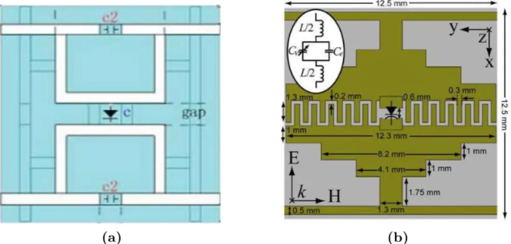
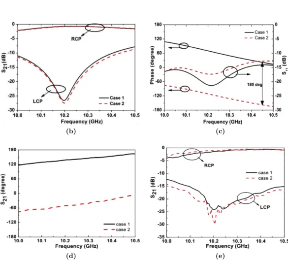
In [79] yet another transmitarray with polarisation control capabilities is presented by the same authors of [78], based on the unit-cell of Fig. 2.18. The authors have suggested two designs of unit-cells for 1-bit phase resolution transmitarray, to operate around 10 GHz. The most complete design presented by the authors consists
2.4 hybrid transmitarray
of two-layer metallic patterns connected by a metallized via-hole as depicted in Fig. 2.18a. A U-slot rectangular patch is used in one side of the structure to receive the incident wave. On the other side, a square ring patch with two triangular corners and loaded with 2 p-i-n diodes is utilized to produce circular polarisation. The p-i-n diodes were used to dynamically select between LHCP and RHCP. The unit-cell operates under two cases: case 1 - p-i-n diode 1 is switched ON while 2 is OFF; case 2 - p-i-n diode 1 is switched OFF while 2 is ON. Simulated results (Fig. 2.18b, Fig. 2.18c) on the unit-cell were further validated on a 8 × 8 transmitarray prototype against experimental results (Fig.2.18d, Fig.2.18e). While in case 1, the transmitarray converts a vertically polarised incident wave to RHCP, in case 2 the transmission phase of the outgoing wave is also shifted by 180◦. Based on the previous unit-cell design [79], the same research group have introduced and characterized in [80], a transmitarray with both reconfigurable polarisation control and beamsteering capabilities. Besides of controlling the polarisation of the re-transmitted EM wave, the proposed transmitarray also has the capability of realising beamsteering in a range of ±45◦ in both elevation an azimuth planes at 4.8 GHz, exhibiting however insertion losses of 5.6 dB over a small bandwidth of 100 MHz, obtained experimentally on a manufactured prototype.
Similarly in [81], it has been presented a 20 × 20 element fully reconfigurable transmitarray based on a 1-bit linear polarisation unit-cell model operating in the Ka-band (27-GHz). A snapshot of both unit-cells and the reconfigurable transmitarray are depicted in Fig. 2.19. The unit-cell is formed in a multi-layer design with a central ground plane (Fig.2.19a) loaded with p-i-n diodes to obtain a wide-band constant phase shift between the two phase states. Circular polarisation is achieved by using the sequential rotation technique previously described, while p-i-n diodes enable LHCP/ RHCPpolarisation switching. However, due to the control of the phase shift by switching on and off the p-i-n diodes, the control of the direction of the out-coming wave is also possible with reported steering ranges of ±60◦ in azimuth and elevation planes.
Finally, in [82] a 1-bit reconfigurable transmitarray that allows control of polarisa-tion as well as antenna beamsteering is presented. The unit-cell of the transmitarray is comprised of two H-shaped slots (Fig. 2.20a) that behave as receiving and trans-mitting coupled microstrip patches. The fact that they are orthogonality disposed relative to each other, it allows X to Y polarisation transformation (of the incident EM wave). In between the transmitter and receiver slot patches, a feeding network that includes 2 p-i-n diodes is responsible to control the phase difference of the arrangement. When the p-i-n diode 1 is OFF and p-i-n diode 2 is ON (Fig.2.20a), a total phase shift of 180◦ is achieved against 0◦ phase shift for the opposite case. The proposed unit-cell operates at a center frequency of 12.5 GHz and it has an overall dimension of 8 × 8 mm2 (λ/3 × λ/3). According to simulation on the unit-cell, the
literature review
(a)
(b) (c)
(d) (e)
Figure 2.18: (a) Transmitarray unit-cell design loaded with p-i-n diodes; S21amplitude and phase response for: (b,c) simulated and (d,e) experimental results, respectively.

![Figure 2.6: Prototype of a single opened fishnet unit-cell layer (images extracted from the work presented in [16]).](https://thumb-eu.123doks.com/thumbv2/123dok_br/18538211.905080/31.892.296.581.107.319/figure-prototype-single-opened-fishnet-images-extracted-presented.webp)

![Figure 2.14: Geometry of transmitarray unit-cell (image extracted from the work presented in [59]).](https://thumb-eu.123doks.com/thumbv2/123dok_br/18538211.905080/40.892.269.698.115.366/figure-geometry-transmitarray-unit-cell-image-extracted-presented.webp)
![Figure 2.17: Transmitarray unit-cell architecture (image extracted from the work presented in [78]).](https://thumb-eu.123doks.com/thumbv2/123dok_br/18538211.905080/44.892.197.752.120.727/figure-transmitarray-unit-cell-architecture-image-extracted-presented.webp)
![Figure 2.19: Snapshot of (a) the active unit-cell and (b) transmitarray for beamsteering and polarisation control (images extracted from the work presented in [81]).](https://thumb-eu.123doks.com/thumbv2/123dok_br/18538211.905080/47.892.178.734.106.411/figure-snapshot-transmitarray-beamsteering-polarisation-control-extracted-presented.webp)