Journal of Computer Science 2012, 8 (11), 1830-1833 ISSN 1549-3636
© 2012 Science Publications
doi:10.3844/jcssp.2012.1830.1833 Published Online 8 (11) 2012 (http://www.thescipub.com/jcs.toc)
Corresponding Author: Sahaya Anselin Nisha, A., Faculty of ECE, Sathyabama University, Chennai-600119, India 1830
Science Publications JCS
DESIGN OF HYBRID COUPLER CONNECTED SQUARE ARRAY
PATCH ANTENNA FOR Wi-Fi APPLICATIONS
1
Sahaya Anselin Nisha A. and
2T. Jayanthy
1
Faculty of ECE,Sathyabama University, Chennai-600119, India 2
Panimalar Institute of Technology, Faculty of ECE,Chennai-600123, India
Received 2012-07-29, Revised 2012-09-08; Accepted 2012-09-19
ABSTRACT
Microstrip patch antennas being popular because of light weight, low volume, thin profile configuration which can be made conformal. Wireless communication systems applications circular polarization antenna is placing vital role. In this study we introduce a new technique to produce circular polarization. Hybrid coupler is directly connected to microstrip antenna to get circular polarization. Also gain is further increased by introducing antenna array technique. Each square in array having length of 4.6mm patch is having thickness of 0.381mm and the dielectric material used FR4. The designed antenna having high gain of 6.26dB and directivity of 5.11dB at the resonant frequency of 3.7GHz. Simulation results shows that the designed antenna characteristic is suitable for Wi-Fi applications.
Keywords: Array Antenna, Circular Polarization, Directivity, Hybrid Coupler, Radiation Pattern
1. INTRODUCTION
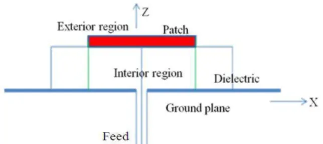
Planar configurations of microstrip technology is placing vital role in the field of antenna (Sarin et al., 2009). Microstrip antenna provides high repeatability of parameters to increase the gain, band width and the size reduction is achieved by using small substrate. Patch can be in any shape like rectangular, circular, square, elliptical sand triangular. Hybrid coupler implementation with Varactor diode and Pin diode is proposed by Sun et al. (2005). Different feeding techniques for UWB antenna are investigated and fabricated (Guo et al., 2002). Figure 1 show the fields associated with an antenna (Yang et al., 2001). Electromagnetic energy coupling in and around patch is done by dielectric material. The electric field is maximum at one end of patch and minimum in other end. This maximum and minimum end will depends the applied signal but electric field at the center of patch is always zero. Electric field in the patch is extended outside patch is causing radiation in a patch and this extended field is known as fringing field (Martin et al., 2007). The proposed antenna is in square array shape with 0.381mm and it resonates at 3.7GHz which includes Wi-Fi and Wi-Max.
1.1. Dual-Fed Circular Polarization Patch Antenna
Polarization of an antenna is defined as the polarization of the wave transmitted (radiated) by the antenna, whereas polarization of radiated wave is defined as property of an electromagnetic wave describing the time varying direction and relative magnitude of the electric-field vector; specifically, the figure traced as a function of time by the extremity of the vector at fixed location in the space and the sense in which it is traced, as observed along the direction of propagation. Polarization may be classified as linear, circular and elliptical. The proposed antenna having circular polarization and is achieved by dual feed in patch antenna. Figure 2 shows the general configuration of dual feed patches (Guo et al., 2004). External polarizer used to categories the dual-fed CP patch antenna they are 3dB hybrid type and the other is an offset-line coupler are used and it produces of equal amplitude but 90° out of phase at its centre frequency.
Figure 3 and 4 shows internal diagram and simulated
diagram of 3db hybrid coupler.
1.2. Hybrid Coupler Design
Sahaya Anselin Nisha A. and T. Jayanthy / Journal of Computer Science 8 (11) (2012) 1830-1833
1831
Science Publications JCS
Fig. 1. Division of fields is associated with an antenna into an interior fields and exterior fields
Fig. 2. Dual-fed CP patches
Fig. 3. Internal diagram of 3dB quad hybrid Coupler
Fig. 4. Simulated Hybrid Coupler
Fig. 5. Square patch antenna arrays
Power dividers and directional couplers, are passive devices used in the field of radio technology such as power division or power combining (Tang et al., 2006). A 3 dB, 90° hybrid coupler is a four-port device, that is used either to equally split an input signal with a resultant 90° phase shift between output signals or to combine two signals while maintaining high isolation between them. However, in a practical device the amplitude balance is frequency dependent and departs from the ideal 0dB difference.
All 90° Power Dividers/Combiners, also known as quadrature hybrids or simply quad hybrids, are reciprocal four port networks (Targonski et al., 1998; Mak et al., 2000). The hybrid coupler or 3 dB directional coupler, in which the two outputs are of equal amplitude, takes many forms. It is beginning when quadrature (90°) 3 dB coupler coupling with outputs 90° out of phased. Now any matched 4-port with isolated arms and equal power division is called a hybrid or hybrid coupler. Today the characterizing feature is the phase difference of the outputs. If 90°, it is a 90° hybrid. If 180°C, it is a 180° hybrid. In this study 90° coupler is designed and connected with antenna to produce circular polarization. According to the impedance choice of the series and stub microstrip transmission lines we can calculate the w/d ratios of those lines in microstrip form by using the following formulas.
Width of Hybrid (w) Eq. 1:
4
24 2
8a
w
8 2
w B 1 In(zB 1) d
w 2
d
2 0.61 In(B 1) 0.39 d
6. −
<
− − −
−
>
π − + −
(1)
Consider Eq. 2:
w 2 d > and
0 c
377 B
2z s
π
= (2)
Dielectric constant (εe) Eq. 3:
r r
c
s 1 s 1 1
s
12d
2 2 1
w
+ − = +
+ (3)
Length of the hybrid (l) Eq. 4:
c o
90 ( 180 ) 1
s k
° π × ° =
Sahaya Anselin Nisha A. and T. Jayanthy / Journal of Computer Science 8 (11) (2012) 1830-1833
1832
Science Publications JCS
1.3. Radiation Element Design
Microstrip antennas that operate as a single element usually have a relatively large half Power beamwidth, low gain and low radiation efficiency. Initially the square patch is designed with each side of 4.2 mm. This patch is arranged to form an array to improve parameters like gain and Range of the radiating structure shows Figure 5. By considering all the elements are placed at regular interval, all the elements are identical, all the elements have uniform (equal) amplitude excitation there can be a linear relative phasing between the elements in the two orthogonal directions the analysis is done. The effect of mutual coupling is depends on antenna type and its design parameters, relative positioning of the elements in the array, feed of the array elements (Chair et al., 2005).
Assuming single mode operation the terminal voltage of one element in terms of current flowing in the others can be written as Eq. 5:
mn mn, pq pq p q
V =
∑∑
Z I (5)where, Zmn, pq defines the terminal voltage at antenna mn due to a unity current in element pq when the current in all the other elements is zero. Thus the Zmn, pq terms represent the mutual impedances when the indices mn and pq are not identical. The driving impedance of the mnth element is defined as Eq. 6:
j
j( p m) xe (q n ) y Dmn mn ,
p q
Z =
∑∑
Z pq e − β − β (6)Incident and reflected waves for E and H field can be written as Eq. 7-10:
(
)
jkz ( yzin z cosi)i i
0 ˆy i ˆz i
E =E a cosθ −a sinθ e+ θ+ θ (7)
o
jk
i i
x 0 i i
ˆ
H =a H e+ (ysinθ +z cosθ) (8)
(
)
jko( yzin r z cos zr)r r
o ˆy r ˆz r
E =E a cosθ −a sinθ θ− − θ + θ (9)
o r r
jk ( y sin z cos )
r r
x o
ˆ
H = −a H e− − θ + θ (10)
The tangential components of electric and magnetic field is:
tan 0
tan
E H
η =
Reflection coefficient of a transmission line with normalized coefficient ZL is given by:
L
L
Z 1 Z 1
− Γ =
+
2. MATERIALS AND METHODS
The ideal method for analysis microstrip antenna are Transmission line model, cavity model and Methos of moment techniques (Targonski et al., 1998; Mak et al., 2000).
2.1. Transmission Line Model
In this model microstrip antenna is represented by two slots of width W and height h, separated by a low impedance transmission line of length L. Some electric field lines are travelling outside the substrate resulting fringing effect that is changing effective dielectric constant. It is a function of the dimensions of the patch and the height of the substrate. Transmission line model is easy to design but it is having less accurate.
2.2. Cavity Model
Transmission line model ignores field variations along the radiating edges. This model provides a better way to model the radiation patterns and is closer in the physical interpretation of the antenna characteristics. The normalized fields within the dielectric can be found more accurately by treating the region as a cavity bounded by electric conductors (above and below) and by magnetic walls along the perimeter of the patch. The disadvantage of this method is complex in nature.
2.3. Method of Moment
In this method, the surface currents are used to model the microstrip patch and the volume polarization currents are used to model the fields in the dielectric slab. The basic form of the equation to be solved by the Method of Moment is:
( )
F g = hWhere:
F = A known linear operator g = An unknown function
h = The source or excitation function
Sahaya Anselin Nisha A. and T. Jayanthy / Journal of Computer Science 8 (11) (2012) 1830-1833
1833
Science Publications JCS
3. RESULTS
A simulator Advanced Design System based on Method of Moment has been used to calculate return loss, radiation pattern. Geometry of proposed antenna is shown in Figure 6. Using the above equations dimensions of hybrid coupler, patch is calculated and the simulation is done using ADS software. Figure 7 shows return loss for proposed antenna and 3-D radiation pattern of hybrid coupled microstrip rectangular patch antenna is shown in Fig. 8 and it is showing the proposed antenna is having circular polarization.
4. DISCUSSION
Reflection coefficient (S11) or return loss is defined as the ratio of reflected power to the incident power. Simulated return loss in hybrid coupled microstrip antenna is-24.083 db at resonant frequency 3.688 GHz.
Fig. 6. Geometry of proposed antenna
Fig. 7. Return loss characteristics
Fig. 8. Radiation pattern
The radiated energy in a particular direction is measured in terms of field strength at a point which at particular distance from the antenna. Radiation pattern is a graph which shows the variation of actual field strength of electromagnetic field at all points which are at equal distance from antenna. So the graph of radiation pattern will be three dimensional. Here the simulated result of radiation pattern shows proposed antenna is having circular polarization.
5. CONCLUSION
Deign of hybrid coupled square microstrip patch array antenna is presented and discussed in this study having return loss is-24.083 db at resonant frequency 3.688 GHz. Circular Polarization is also achieved by using hybrid coupler. Proposed antenna is suitable for wireless applications at 3.7GHz.
6. REFERENCES
Chair, R., C.L. Mak, K.F. Lee, K.M. Luk and A.A. Kishk, 2005. Miniature wide-band half U-slot and half E-shaped patch antennas. IEEE Trans. Antennas Propag., 53: 2645-2652. DOI: 10.1109/TAP.2005.851852 Guo, Y.X., K.M. Luk, K.F. Lee and R. Chair, 2002. A
quarter-wave U-shaped patch antenna with two unequal arms for wideband and dual-frequency operation. IEEE Trans. Antennas Propag., 50: 1082-1087.DOI: 10.1109/TAP.2002.801285
Guo, Y.X., M.Y.W. Chia, Z.N. Chen and K.M. Luk, 2004. Wide-band L-probe fed circular patch antenna for conical-pattern radiation. IEEE Trans. Antennas Propag., 52: 1115-1116.DOI: 10.1109/TAP.2004.823971 Mak, C.L., K.M. Luk, K.F. Lee and Y.L. Chow, 2000.
Experimental study of a microstrip patch antenna with an L-shaped probe. IEEE Trans. Antennas Propag., 48: 777-783. DOI: 10.1109/8.855497 Martin, M.A., B.S. Sharif and C.C. Tsimenidis, 2007.
Probe fed stacked patch antenna for wideband applications. IEEE Trans. Antennas Propag., 55: 2385-2388. DOI: 10.1109/TAP.2007.901924
Sarin, V.P., N. Nassar, V. Deepu, C.K. Ananadan and P. Mohahana et al., 2009. Wideband printed microstrip antenna for wireless communications. IEEE Antennas Wireless Propag. Lett., 8: 779-781. DOI: 10.1109/LAWP.2009.2026193
Sun, K.O., C.C. Yen and D.V. Weide, 2005. A size reduced reflection-mode phase shifter. Mic. Opt. Technol. Lett., 47: 457-459.DOI: 10.1002/mop.21198
Tang, C.W., M.G. Chen, Y.S. Lin and J.W. Wu, 2006. Broadband microstrip branch-line coupler. Elec. Lett., 42: 1458-1460. DOI:10.1049/el:20063025 Targonski, S.D., R.B. Waterhouse and D.M. Pozar, 1998.
Design of wide-band aperture-stacked patch microstrip antennas. IEEE Trans. Antennas Propag., 46: 1245-1251.DOI: 10.1109/8.719966