DOI: http://dx.doi.org/10.1590/1806-9126-RBEF-2018-0206 Licença Creative Commons
A study of strain and deformation measurement using the
Arduino microcontroller and strain gauges devices
Anderson Langone Silva
1, Marcus Varanis
*1, Arthur Guilherme Mereles
1, Clivaldo Oliveira
1,
José Manoel Balthazar
21Universidade Federal da Grande Dourados, Faculdade de Engenharia, Dourados, MS, Brasil
2Universidade Tecnológica Federal do Paraná, Departamento de Eletrônica, Campus Ponta Grossa, PR, Brasil
Received on July 09, 2018; Revised on October 09, 2018; Accepted on November 06, 2018.
This paper presents a methodology for the measurement of strain by means of strain-gauges, where the data acquisition is done by using an Arduino Uno board, due to the low-cost and the easy manipulation of this microcontrollers. The measured signal conditioning is performed by means of a Wheatstone Bridge and then discretized by an Analog-Digital Converter (ADC) external to the Arduino. For the validation of the proposed measurement system, experiments are performed on a cantilever beam and on a cantilever-supported shaft, where the experimental results are compared with those obtained analytically and by simulation using the finite element method. The results obtained are in agreement with the literature and demonstrate that the proposed system has satisfactory accuracy.
Keywords:Strain gauge, Arduino, Low-cost data acquisition
1. Introduction
In many practical situations in engineering, the knowl-edge of the stresses and strains that are applied in a structure is of vital importance, since the predictability of the materials depend closely on these parameters. Be-sides, it is important to avoid deformations so large that they may prevent the structure from fulfilling the purpose for which it was intended [1]. Generally, mathematical models or finite elements methods (FEM) are needed to predict the stresses in a structure. There are some situations, however, were the modeling is not possible or its results are rough approximations that do not agree with the real loads acting on the structure. In these cases, in order to avoid overdimensioning, the experimentation is the way around.
There are many experimental procedures aimed at measuring mechanical strain, such as using strain-gauges, which can be optical [8] or mechanical [9]; or using elec-trical strain gauges, that can be based on resistive [12], capacitive [4], inductive [3] and photoelectric [10]. One of the most common applied method is based on the use of resistive-based strain-gauges. These devices allow the strain to be measured directly by measuring the change in the electrical resistance of them as they are subjected to deformations, which is commonly done by using a Wheatstone bridge. The gauges can also be used to mea-sure forces and torques acting on a structure, as these quantities are directly related to strain. However, since
*Correspondence email address: [email protected].
the strain-gauges are expensive and not reusable, the overall cost of the experimental procedure is generally high.
In such cases, the use of the Arduino microcontroller together with low-cost sensors is encouraged. This use brings a lot of benefits such as the easy implementation and low overall cost of the apparatus. For some exam-ples, in [5] a low-cost Arduino-based wire strain-gauge is proposed for earth flow/landslide monitoring, where a prototype was built with an Arduino Uno board, a data logging RTC and a operating temperature sensor; the field tests showed high reliability of the experimental apparatus. In [7] an ultra-light strain-gauge device for the assessment of the mechanical properties of the human skin in vivo is presented, where the Arduino Mega 2560 was used to acquire the dada from the sensors. Some other applications are presented in [6], [2] and [13].
This work consists of some sections that are described as follows. In the section 2 the mathematical models used to obtain the analytical results are presented. In the subsection 2.1 the deformation model for the cantilever beam is presented and in the subsection 2.2 the model for a crimped-supported shaft is shown. In the section 3 the configuration used in the experiment is presented, in the subsection 3.1 the strain gauge is presented, in the sub-section 3.2 the operation and the possible configurations of the Wheatstone bridge is presented, and in the section 3.3 the circuit of the proposed data acquisition system and its components is discussed. In the section 4 the experimental procedures used to perform the tests are discussed and the section ref results discusses the results obtained. In the section 6, some final considerations are made.
2. Analytical models
In this section, the analytical models used to perform the comparison with the experimental results are discussed. In the subsection 2.1 the mathematical model used to obtain the analytical deformation of the cantilever beam under bending is presented. In the subsection 2.2, it is presented the mathematical model used to obtain the analytical deformation of a crimped-supported shaft. The stress and strain models used in this paper are widely explored in the literature, both analytical methods [1,14–16] and methods based on finite elements [17–19].
2.1. Cantilever beam
For the experiment of the clamped beam at one end and free at the other we have the following expression for the tension at the surface of the beam, [1,14–16]
σ= M ρ
I (1)
whereM is the resulting bending moment,Iis the
mo-ment of inertia of the cross-sectional area, and rho is
the distance from the neutral line to the point of interest. The moment of inertia is given by
I=bh
3
12 (2)
whereb is the width of the beam andhis its thickness.
Substituting Equation (2) into Equation (1) and c for h/2 we have
σmax=
6M
bh2 (3)
which corresponds to the tensionσmaxon the surface of the beam when subjected to a bending momentM. It is
known that the deformationǫcan be obtained by means
of the Equation 4, known as the Hooke’s Law, whereE
is the modulus of elasticity of the material.
ǫ=Eσ (4)
Substituting Equation 3 into Equation 4 gives the equation for the deformation at the beam surface when subjected to bending, Equation 5.
ǫ=E6M
bh2 (5)
2.2. Crimped-supported shaft
It is known that the maximum shear stressτmaxon the surface of an axis with radius c subjected to a torque
with intensityT is given by [1,14–16]
τmax=
T c
J (6)
whereJis the polar moment of inertia of the shaft section,
in this case given by
J = πc
4
2 (7)
Replacing the equation 7 in the equation 6 gives the equation for the case under analysis.
τmax=
2T
πc3 (8)
In order to obtain the shear deformation, the Hooke’s Law for torsion is applied, according to the equation 9, in the Equation 8.
τ=Gγ (9)
γ=2T G
πc3 (10)
In equations 10 and 9 the constantGcorresponds to
the shear modulus of the material.
Um estudo aprofundado sobre o assunto pode ser visto em [CITAR POPOV, HARDOG E TIMOSHENKO]. POPOV, Egor Paul; BALAN, Toader A. Engineering mechanics of solids. Englewood Cliffs, NJ: Prentice Hall, 1990. DEN HARTOG, Jacob Pieter. Advanced strength of materials. Courier Corporation, 2014.
3. Experimental setup
In this section the experimental aspects of the work are discussed. The subsection 3.1 treats strain gauges, the subsection 3.2 presents the Wheatstone bridge and in the subsection 3.3 the data acquisition system and the devices used are presented.
3.1. Strain gauge
increase its size, consequently generating a variation in the initial resistance of the strain gauge, being the variation of the resistance with the deformation linear. It is possible to find strain-gauges of electrical resistance in the most diverse formats, but in this work only the general purpose strain-gauge for uniaxial use are used. In Figure 1, two common formats of strain-gauges are shown. The Figure 1a shows an uniaxial general purpose strain-gauge, which is the most used model in deformation instrumentation in everyday applications. In the Figure 1b, it is shown a triaxial rosette-type strain-gauge, used when it is necessary to know the stress state of the test body and it consists of three uniaxial strain-gauges.
An important factor of strain gauges is their sensi-tivity to deformation, commonly called as gauge factor,
GF. This factor is given by the relationship between
the resistance variation and the deformation, as shown in Equation 11. By manipulating the equation 11 it is possible to obtain an equation for the strain as a func-tion of the variafunc-tion of the resistance of the strain-gauge, Equation ref strain. In equations 11 and ref strain,K
is the gauge factor,R0is the nominal resistance of the strain-gauge,∆is its variation, andǫis the strain that
the strain gauge was submitted [20,21].
K= ∆Rs/Rs
ǫ (11)
∆Rs
Rs
=Kǫ (12)
For strain analysis in the proposed systems, strain-gauges model BF350-3AA were utilized, which have nom-inal resistance of 350 ohms and gauge factor of 2.
3.2. Wheatstone bridge
In resistive sensors in which only small variations of re-sistance occur, it is necessary to use auxiliary circuits for their instrumentation, in order to allow a good sensitivity to the measuring instrument. In the case of deformation
(a) (b)
Figure 1:Two common strain gauge formats: 1a general purpose uniaxial strain gauge and 1b triaxial rosette.
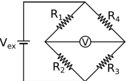
instrumentation, where the resistance variations of the strain-gauges are minimal, the Wheatstone bridge circuit is used. This circuit allows one to measure the resistance of unknown resistors through the balance of the circuit, allowing to carry out measurements with great precision. The generic circuit of the Wheatstone Bridge is shown in Figure 2, whereR1,R2, R3 andR4 are resistors,Vex is a power supply of direct current andV is a voltmeter.
Applying the Kirchhoff’s first law, a relationship between the supply voltageVex, the voltage read by the voltmeter
V and the values of the resistors is obtained, Equation
13, [20,21].
V =
R
3
R3+R4−
R2
R1+R2
Vex (13)
The Wheatstone Bridge circuit can be a quarter, half or full bridge type, depending on the number of transducers and the required accuracy. Its principle of operation is based on the voltage equilibrium between the two arms of the circuit. In order to have voltage equilibrium,V = 0,
the relation in Equation 14 must be satisfied.
R1
R2
=R4
R3 (14)
In the quarter bridge circuit only an active strain gauge is used, so in the circuit, the resistorR4is replaced by the strain gaugeS4, as in the Figure 3a, so that the resistors
R1,R2 andR3are passive resistors with fixed resistance values. In order to maintain the output of the circuit null, the resistorR1can be chosen to have the same resistance as S1, while R2 and R3 can be equal, in this way the equilibrium of Equation 14 is obtained. Although this circuit is easy to assemble due to the existence of only
Figure 2:Wheatstone bridge standard circuit.
(a) (b) (c)
one strain gauge, the measurements are susceptible to inacurracies due to temperature.
Considering this case under analysis, taking the equa-tion 13, considering all resistors with resistanceRand the
strain-gaugeS1 with resistance equal toR±∆R where
+∆Rcorresponds to traction,+ǫ, and−∆Rcorresponds
to compression, −ǫ, we get the equation 15.
V =
R 2R+ ∆R−
1 2
Vex (15)
Manipulating the equation 15 and dividing the numer-ator and denominnumer-ator byR, the equation 16 is obtained,
where the term ∆R/R can be replaced according to
Equation 12, obtaining the equation 18.
V =
∆R R
4 + ∆R R
Vex (16)
V Vex
= Kǫ
4 +Kǫ (17)
In the equation 17, the ratio of the voltages,V /Vex has units of[V /V], for convenience is usually multiplied by
a factor of1000with the purpose of the unit of the ratio
between the voltages to be[mV /V], also for convenience
the equation is multiplied by10−6thus the deformation ǫpass to bemicrostrain,[µm/m], obtaining the equation
18.
V Vex
= Kǫ×10−
3
4 +Kǫ×10−6 (18)
In the half-bridge circuit there are two active strain-gauges, so that the resistorsR3 andR4are replaced by the strain-gaugesS3 andS4, respectively, as in Figure 3b. In this case it is common for the strain-gauges to be positioned so that whileS3is subject to a deformation−ǫ,
S4 is subject to a+ǫdeformation. In order to maintain the equilibrium of the circuit, the resistorsR1andR2are chosen so that they are equal, maintaining the equality of Equation 14. In this configuration, due to the use of two sensors, the thermal effects are minimized.
In this case, by making all resistors with resistance equal toR, the strain-gauge S3equals R−∆Rand the strain-gaugeS4equalsR+ ∆R. Applying the equation 13 gives the equation 19, which is manipulated similarly to the previous case to obtain the equation 20.
V =−∆R
2RVex (19)
V Vex
=−Kǫ×10
−3
2 (20)
In the complete bridge circuit four active strain-gauges are used, S1, S2, S3 and S4, according to Figure 3c. In one typical assembly the strain-gaugesS2andS4 are arranged so that they are subjected to traction,+ǫ, while
the strain-gaugesS1andS3are subjected to compression, − epsilon. In this configuration no resistors are used
to complement the circuit and the thermal effects are minimized to the maximum.
In this case all the elements of the Wheatstone bridge are strain-gauges, considering the strain-gaugesS1and
S3with resistanceR−∆Rand the strain-gaugesS2and
S4 with resistanceR+ ∆R, substituting these values in the equation 13 we obtain the Equation 21. By means of the manipulations already carried out, the equation 22 is obtained.
V =−∆R
R (21)
V Vex
=−Kǫ×10−3 (22)
In this work, due to the educational approach of strain instrumentation, the quarter bridge circuit is used, which presents good results for the proposed purpose. For ap-plications where greater precision and temperature com-pensation are required, it is recommended to use circuits such as half bridge or full bridge. For the implementation of the one-quarter bridge circuit of this work, 680 ohm resistors were used and to balance the circuit out a 470 ohms trimpot was used and configured to zero the circuit output voltage.
3.3. Data-acquisition
The recent technological advances have contributed to the popularization and miniaturization of electronic de-vices. Among the microcontrollers popularized by users less experienced in programming and electronics, we can mention those of the PIC family and, more recently, the family of Arduino prototyping boards, based on the AT-mega family of microcontrollers manufactured by Atmel. Arduino platforms stand out because they have their own programming language based on C ++, adapted to be simple and intuitive, and are marketed in the form of ready-to-use boards, which include the microprocessor and other components necessary for their use, eliminat-ing the need for the user to create complex electronic circuits for the use of the microcontroller.
Due to its low cost, it has been discussed the use of Arduino microcontrollers in engineering applications that commonly involve instrumentation, monitoring of ma-chines and structures and control of mechanical systems. In [22] the Arduino microcontroller was used along with low-cost sensors for vibration instrumentation. As in [11], the Arduino microcontroller is used for the instrumen-tation of vibrations in systems with various degrees of freedom by means of MEMS accelerometers. In [23] the Arduino was used with the wireless MEMS sensors in order to monitor the Himera viaduct in Italy.
(a) (b) (c)
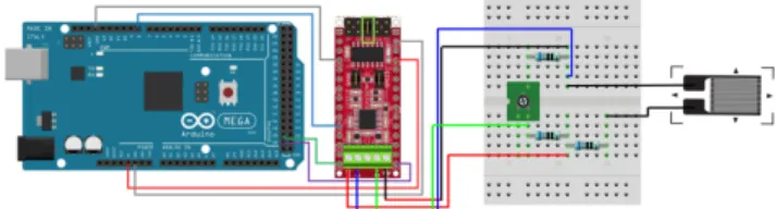
Figure 4: Boards utilized for data acquisition: 4a Arduino Mega2560 R.3, 4b Nanoshield Load Cell module and 4c Base Board.
those from load cells and Wheatstone Bridges, because these systems return low-amplitude signals. To facilitate the connection of the Arduino to the Nanoshield LoadCell module a Base Board, Figure 4c, also manufactured by Circuitar was used, but this board is only used in order to facilitate the connection of one or more Nanoshield LoadCell modules. Although these modules have been used, others may also be used without any accuracy loss.
The Whetstone Bridge circuit implemented was pow-ered with a 5 V DC voltage from the Arduino, while its signal outputs were connected to the amplification module mentioned before, where the amplification and discretization of the signal is performed. The choice of using an external ADC is be due to the resolution of most Arduino microcontrollers being 12 bits, thus the signal needs to be more amplified to have the same reso-lution as the Nanoshield LoadCell module, limiting the range of the data acquisition system. Figure 5 shows the connection diagram of the components used.
To program the Arduino assembly and the amplifica-tion module, it was utilized a library provided by the manufacturer of the Nanoshield Load Cell module, that can be found in its repository, [24], and to acquire the data an example sketch provided by the library was used.
4. Experimental proccedures
The bonding procedure of strain gauges must be thor-oughly performed to avoid measurement errors, starting with the preparation of the surface for bonding. The surface where the strain-gauge will be glued must be carefully sanded using a fine water sandpaper with a granulometry of about 220. First, the surface should be
Figure 5:Connection diagram of the components for the data acquisition.
sanded at 45°of the center line of the strain-gauge, then sanded at -45°of the same line, so that the angle between the resulting lines of this process is 90°, forming an X. Af-ter this procedure, for educational purpose experiments, the bonding site must be cleaned with alcohol or acetone, but in applications that require more precision specific products should be used. After the cleaning, it is neces-sary to mark the bonding site, preferably using a pencil with fine graphite, so that there is no large graphite de-position in the place, which could end up affecting the measurement. The line where the deformation is to be measured and an auxiliary line at 90°, corresponding to the transverse sensitivity axis of the strain-gauge, need to be marked.
After the preparation process for the strain gauge bonding, the bonding process begins. For this, it is needed a glass base, previously cleaned with alcohol, tweezers, transparent tape and instant glue. To better handle the strain gauge with the tweezers, place it on the glass base so that its grid and solder terminals are up, note that the strain gauges should only be handled using the tweezers, avoiding any contact with the hands, reducing any risk of damage in them. Besides, the oiliness that is present in the hand can cause the oxidation of the strain-gauge grid. With the transparent tape glue the strain gauge onto the glass base. When removing the tape the strain gauge must be removed with the tape, still glued in it. The bonding of the strain-gauge to the tape is performed to facilitate the correct positioning and bonding of the transducer to the surface where the deformation will be measured. The tape and the strain gauge must be carefully positioned on the surface so that the previously marked lines match the strain gauge indicators. Figure 6 illustrates the correct positioning of the strain gauge. After the correct positioning, one must carefully peel off part of the tape until the strain gauge is raised to insert a small amount of instant glue under it, quickly reposition the tape as before and press the strain gauge so that bubbles do not form under it. Again, in applications where higher precision is required, it might be necessary to use specific products and more elaborate processes for bonding. After the cure time of the adhesive, carefully remove the tape and inspect the strain gauge with a magnifying glass. If the strain gauge has bubbles under its surface or if it is incorrectly positioned, remove it, discard it, and perform the preparation and gluing procedures again.
Figure 6: Correct positioning of the strain gauge at the mea-surement point.
main stresses occur. In experiments to measure torsion in shafts where good precision is required, a correct marking of the lines of the shaft must be performed, positioning the shaft horizontally, which can be done with the aid of a splitting device.
For the cantilever beam experiment a force of 0.981N
was applied, by means of positioning a block with known mass being at the free end of the beam, and the strain gauge was glued at 30 mm from the fixed end in the
center of the upper face. In the torsion shaft experiment a torque of 3.6N/mwas applied and the strain gauge
was glued at 45°of the axis of symmetry of the workpiece. In both experiments, 256 points were acquired.
The experiments were performed in two stages for each system. First, the force or torque are applied and, after a certain time, they were took off once. As in the second stage, the described process were performed twice, to analyze if the proposed measurement system has repeata-bility. The test benchs utilized for the experiments can be seen in Figure 7 and in Figure 8 the strain-gauges, already glued in the mechanical systems analyzed, are shown with more detail.
5. Results and discussion
Deformation measurements were performed in the two proposed systems, performing five measurements in each system for each case studied. In both systems, two cases were analyzed, in the first a momentary load was applied
(a) (b)
Figure 7:Test benches for experimental validation of the pro-posed measurement system: (7a) Cantilever beam and (7b) Crimped-supported shaft under torsion.
(a) (b)
Figure 8:Strain-gauges glued to the analyzed mechanical system (8a) in experiment 1 and (8b) in experiment 2.
to the system and in the second case the same load was applied twice.
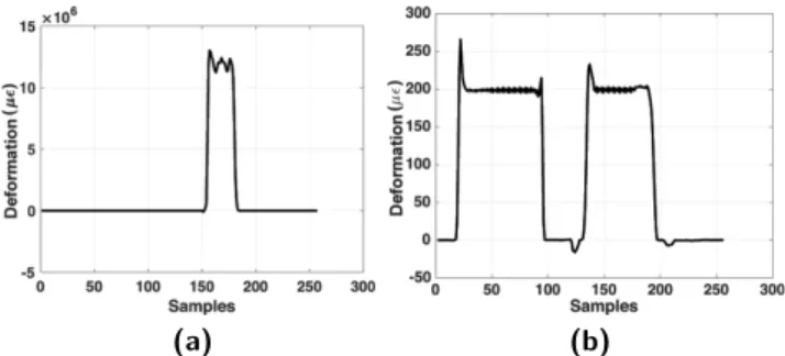
The signals were acquired with 256 points and sampling frequency of 80 Hz, resulting around 3 seconds of data acquisition. In Figure 9, it is presented two strain signals in the time domain of the proposed system, where Figure 9a presents a signal for the first case studied and Figure 9b for the second case.
As the deformation signals are obtained in the time domain and the load depend on the time, it is necessary to manipulate the measured signal to obtain the magni-tude of the observed strain, for which the mean value of the deformation measured is considered as the resulting deformation on the proof body. In the first system, the cantilever beam, the deformation obtained in the experi-ment using the proposed method was 207.3µǫ, whereas
in the second system, the crimped-supported shaft, the strain obtained was 13.3µǫ.
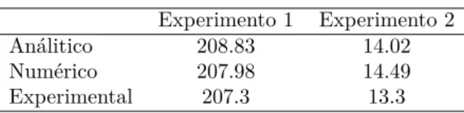
By means of the mathematical models presented in the section 2, a strain of 208.83µǫwas obtained for the first
system and of 14.02µǫfor the second, while the results
obtained through numerical simulation by finite elements resulted in 207.98µǫand 14.49µǫ, respectively for the
first and second systems. For a better visualization of the results, they are presented in the Table 1.
The obtained results show that the proposed system has good efficacy for the proposed application, present-ing satisfactory accuracy, because the results obtained were close to the analytical and numerical results, and presented low dispersion.
(a) (b)
Table 1:Resultados obtidos.
Experimento 1 Experimento 2 Análitico 208.83 14.02 Numérico 207.98 14.49 Experimental 207.3 13.3
6. Conclusions
In this work, it was proposed an alternative to com-mercial deformation instrumentation systems trough the Arduino microcontroller and low cost components. The main purpose of using low cost components is to allow un-dergraduate students who normally do not have contact with deformation instrumentation, due to the high cost of the equipment and the complexity of their operation, to do practical experiments that involve programming, electronics and instrumentation in a simple and intuitive way.
The proposed system proved to be reliable for the proposed purpose, since it presented good repeatability, there being no great dispersion between the samples, and it also presented good precision, obtaining values close to the numerical and analytical ones. The hardware used is of easy operation and its components are also well documented in the literature.
In future projects we intend to apply the methodology of measurement of deformation proposed to more complex systems, using different configurations of the Weatstone bridge and under different conditions of loads, as impact and dynamic loads.
Acknowledgements
The authors acknowledge the Conselho Nacional de De-senvolvimento Científico e Tecnológico (CNPq) for the support.
References
[1] F.P. Beer, E.R.Johnston Jr., J.T. Dewolf and D.F. Mazurek, Mechanics of Materials(McGraw-Hill, New York, 2006).
[2] D.B. Biggs and J.A. Shaw,In Behavior and Mechanics of Multifunctional Materials and Composites 2016 (In-ternational Society for Optics and Photonics, Las Vegas, 2016), p. 98000D.
[3] J.C. Butler, A.J. Vigliotti, F.W. Verdi and S.M. Walsh, Sensors and Actuators A: Physical102, 61 (2002). [4] D.J. Cohen, D.M. Mitra, K. Peterson and M.M.
Mahar-biz, Nano letters12, 1821 (2012).
[5] L. Guerriero, G. Guerriero, G. Grelle, F.M. Guadagno and P. Revellino, Natural Hazards and Earth System Sciences17, 881 (2017).
[6] E.S.B. Ismail, M.H. Habaebi and M.R. Islam, in 2017 IEEE 4th International Conference on Smart Instru-mentation, Measurement and Application (ICSIMA),
(International Islamic University Malaysia, Putrajaya, 2017) p. 1.
[7] E. Jacquet, S. Joly, J. Chambert, K. Rekik and Patrick Sandoz, Skin Research and Technology23, 531 (2017). [8] L. Laloui, M. Nuth and L. Vulliet, International Journal for Numerical and Analytical Methods in Geomechanics
30, 763 (2006).
[9] K.H. Lim, C.M. Chew, P.C.Y. Chen, S. Jeyapalina, H.N. Ho, J.K. Rappel and B.H. Lim, Journal of biomechanics
41, 931 (2008).
[10] A. Lonsdale, Sensors-the Journal of Applied Sensing Technology18, 51 (2001).
[11] M. Varanis, A.L. Silva and A.G. Mereles, Revista Brasileira de Ensino de Física40, e1304 (2017). [12] S. Wen and D.D.L. Chung, Cement and Concrete
Re-search31, 665 (2001).
[13] J. Wissman, A. Perez-Rosado, A. Edgerton, B.M. Levi, Z. Karakas, M. Kujawski, A. Philipps, N. Papavizas, D. Fallon, H. Bruck and E. Smela, Smart Materials and Structures,22, 085031 (2013).
[14] E.P. Popov and T.A. Balan,Engineering mechanics of solids(Englewood Cliffs, Prentice Hall, 1990).
[15] S. Timoshenko,Strength of materials Part 1(Krieger Publishing Company, Malabar, 1940).
[16] J.M. Gere and B.J. Goodno,Mechanics of Materials 5th (Brooks Cole, Boston, 2001).
[17] O.C. Zienkiewicz and R.L. Taylor,The finite element method for solid and structural mechanics(Elsevier, Am-sterdã, 2005).
[18] K.J. Bathe,Finite element method (John Wiley & Sons, New Jersey, 2008).
[19] T.J.R. Hughes,The finite element method: linear static and dynamic finite element analysis(Courier Corpora-tion, Chelmsford, 2012).
[20] R.S. Figliola and D. Beasley, Theory and design for mechanical measurements (John Wiley & Sons, New Jersey, 2015).
[21] J.P. Holman and W.J. Gadja,Experimental methods for engineers(McGraw-Hill, New York, 2001).
[22] M. Varanis, A.L. Silva, P.H.A. Brunetto and R.F. Gre-golin, Revista Brasileira de Ensino de Física38, 1301 (2016).
[23] F.L. Francesco, G. Navarra and M. Oliva, Meccanica52, 3221 (2017).