Mestre em Biotecnologia
Insights into the structure and reactivity
of the catalytic site of nitrous oxide
reductase
Dissertação para obtenção do Grau de Doutor em Bioquímica – Especialidade em Bioquímica Física
Orientador: Doutora Isabel Maria Andrade Martins Galhardas
de Moura, Professora Catedrática Aposentada da Faculdade
de Ciências e Tecnologia da Universidade Nova de Lisboa
Co-orientador: Doutora Sofia Rocha Pauleta, Investigadora
Principal da Faculdade de Ciências e Tecnologia da
Universidade Nova de Lisboa
Co-orientador: Doutor Oliver Einsle, Professor da Universidade
de Freiburg, Alemanha
Júri:
Presidente: Prof. Doutor Manuel Luís de Magalhães Nunes da Ponte Arguentes: Prof. Doutor José João Galhardas de Moura
Prof. Doutor Simone Dell’Acqua
Vogais: Prof. Doutora Margarida Maria Portela Correia dos Santos Romão Prof. Doutora Maria Alice Santos Pereira
Prof. Doutora Isabel Maria Andrade Martins Galhardas de Moura
Mestre em Biotecnologia
Insights into the structure and reactivity of the
catalytic site of nitrous oxide reductase
Dissertação para obtenção do Grau de Doutor em Bioquímica – Especialidade em Bioquímica Física
Orientador: Doutora Isabel Maria Andrade Martins Galhardas de
Moura, Professora Catedrática Aposentada da Faculdade de Ciências
e Tecnologia da Universidade Nova de Lisboa
Co-orientador: Doutora Sofia Rocha Pauleta, Investigadora Principal
da Faculdade de Ciências e Tecnologia da Universidade Nova de
Lisboa
Co-orientador: Doutor Oliver Einsle, Professor da Universidade de
Freiburg, Alemanha
Júri:
Presidente: Prof. Doutor Manuel Luís de Magalhães Nunes da Ponte Arguentes: Prof. Doutor José João Galhardas de Moura
Prof. Doutor Simone Dell’Acqua
Vogais: Prof. Doutora Margarida Maria Portela Correia dos Santos Romão Prof. Doutora Maria Alice Santos Pereira
Prof. Doutora Isabel Maria Andrade Martins Galhardas de Moura
nitrous oxide reductase
Copyright by Cíntia Catarina Sousa Carreira, Faculdade de Ciências e Tecnologia da Universidade Nova de Lisboa e Universidade Nova de Lisboa
Outubro 2017
v
O meu percurso científico iniciou-se neste laboratório e tornou-se mais fácil com a presença de muitas pessoas que me apoiaram em vários momentos e que contribuíram para o meu desenvolvimento como pessoa e como investigadora. Estas pessoas não ficarão esquecidas, e a todas o meu sincero obrigada!
Em primeiro lugar, agradeço à Professora Isabel Moura, pela orientação do trabalho e discussões científicas e por me ter apoiado e motivado desde a licenciatura.
Quero fazer um agradecimento especial à Doutora Sofia Pauleta por me ter orientado, por todos os conhecimentos que me transmitiu e oportunidades que me concedeu. Estas são poucas palavras para descrever todo o apoio, disponibilidade e incentivo que sempre me deu e por isso estou-lhe grata.
Ao Professor Oliver Einsle, agradeço ter aceite ser co-orientador desta tese e por me receber sempre bem no seu laboratório.
Agradeço ao Professor José Moura a possibilidade de poder trabalhar no seu laboratório e pelo seu entusiasmo pela ciência e cultura, sempre contagiante.
À Professora Margarida Romão agradeço por me ter recebido no seu laboratório e por todo o conhecimento científico que me transmitiu, bem como a sua disponibilidade para discutir o trabalho.
Aos autores e co-autores dos trabalhos publicados e em fase de escrita, agradeço o seu contributo, nomeadamente ao Professor Edward Solomon, Esther Johnson, Simone Dell’Acqua, Olga Mestre e Rute Nunes.
Quero também agradecer à Anja Wüst por todo o apoio na execução e desenvolvimento do trabalho no laboratório do Professor Oliver Einsle.
Aos colegas de laboratório que estão e que por ali foram passando, obrigada pela preciosa ajuda, amizade, boa disposição e bom ambiente que me proporcionaram durante estes anos. O vosso apoio e motivação foram essenciais para concluir esta etapa. Não posso ainda deixar de mencionar algumas pessoas que me marcaram neste percurso:
À Susana, à Olga e ao Rui que me apoiaram e proporcionaram imensos risos, obrigada por todos esses momentos! À Luísa e à Célia agradeço por sempre se mostrarem disponíveis para me ajudar e aconselhar.
Rute, aprender e trabalhar contigo foi muito gratificante, mas mais que isso é reconfortante a amizade que permanece. Obrigada por tudo!
vi positivos, em especial durante a escrita da dissertação.
Deixo um especial agradecimento à Ana Maria por toda a amizade e paciência, sobretudo nestes últimos meses.
Aos meus pais e à minha irmã agradeço todo o carinho e apoio incondicional que me deram. Obrigada por tudo o que fizeram por mim, pelas oportunidades que me proporcionaram e por acreditarem sempre em mim!
vii
atmosphere comes from the incomplete denitrification in bacteria. N2O can only be detoxified by
nitrous oxide reductase (N2OR), which catalyzes the last step of this pathway. This enzyme contains two distinct centers per monomer: CuA, the electron transfer center and “CuZ”, a tetranuclear copper-sulfide center, which can exists in two forms CuZ(4Cu2S) and CuZ*(4Cu1S). Most of the studies on the denitrification pathway have used soil denitrifying bacteria as models, while marine bacteria are understudied. This thesis presents an analysis of denitrification pathway of Marinobacter hydrocarbonoclasticus a marine bacterium capable of respiring nitrate under
oxygen-limiting conditions. Here, the effect of pH (6.5, 7.5 and 8.5) on the denitrification pathway of this organism, as well as on the N2OR isolated from each of those growths, was investigated.
These enzymes were characterized through biochemical, spectroscopic and structural studies. The expression profile of genes encoding the enzymes and accessory proteins involved in denitrification was analyzed, together with quantification of the by-products, nitrate and nitrite. These results showed lower levels of nirS expression at pH 6.5, which correlates with the
accumulation of nitrite detected. In parallel, whole-cells reduction rates of NO and N2O
demonstrated that denitrification is impaired at more acidic conditions, as the whole-cells are not able to reduce external N2O when grown at pH 6.5.
The N2OR isolated from each growth exhibits differences at the “CuZ center”. At acidic growth
conditions, N2OR has “CuZ center” mainly as CuZ*(4Cu1S), whereas when isolated from growths
at 7.5 and 8.5, it is mainly as CuZ(4Cu2S). This was supported by spectroscopic data, sulfide quantification, and inspection of “CuZ center” X-ray structure, demonstrating the presence of an additional sulfur atom in the CuZ(4Cu2S) form. The effect of exogenous ligands on both forms of the “CuZ center” was re-visited and clarified.
Direct electrochemistry of N2OR is reported for the first time, with the two signals observed,
assigned to CuA and CuZ(4Cu2S) centers, with reduction potentials being in line with the ones determined by potentiometry (272 ± 10 mV and 65 ± 10 mV vs SHE at pH 7.6, respectively). This
form of N2OR has lower specific activity (0.004 ± 0.001 U/mg) in the presence of physiological
electron donor, cytochrome c552, compared to a N2OR with CuZ*(4Cu1S) (1.25 ± 0.07 U/mg).
Fully reduced CuZ*(4Cu1S) is catalytically competent and in the presence of a stoichiometric amount of N2O originates CuZº intermediate. CuZº species can be reduced through intramolecular
electron transference (IET) from CuA center, in a reaction 104 faster than IET in the CuZ*(4Cu1S).
In the absence of substrate or electrons a novel “CuZ center” intermediate species is formed with a maximum absorption band at 617 nm, and having a [1Cu2+-3Cu1+] oxidation state. These studies
shed new lights on the catalytic cycle, which was reassessed and discussed here.
Keywords: Marinobacter hydrocarbonoclasticus, denitrification, nitrous oxide reductase, “CuZ
ix
estufa advém da incompleta desnitrificação em bactérias. O N2O só pode ser biologicamente
reduzido por acção da reductase do óxido nitroso (N2OR), que cataliza a última etapa desta via.
Esta enzima contém dois centros distintos por monómero: CuA, o centro de transferência de electrões e o “CuZ”, um centro tetranuclear de cobre-enxofre, que pode existir em duas formas CuZ(4Cu2S) e CuZ*(4Cu1S).
Na maioria dos estudos existentes referentes à via da desnitrificação, foram utilizadas bactérias desnitrificantes do solo como modelos, enquanto em bactérias marinhas esta via foi parcamente estudada. Nesta tese é apresentada uma análise da via da desnitrificação de Marinobacter
hydrocarbonoclasticus, uma bactéria marinha capaz de respirar nitrato em condições limitantes de
oxigénio. Aqui, o efeito do pH (6.5, 7.5 e 8.5) na via da desnitrificação deste organismo, assim como na enzima isolada a partir de cada um desses crescimentos, foi investigado. Estas enzimas foram caracterizadas por estudos bioquímicos, espectroscópicos e estruturais.
O perfil de expressão dos genes que codificam para as enzimas e proteínas auxiliares envolvidas na desnitrificação foi analisada, em conjunto com a quantificação dos seus subprodutos, nitrato e nitrito. Estes resultados mostraram baixos níveis de expressão de nirS a pH 6.5, que está
correlacionado com a acumulação de nitrito detectada. Em paralelo, a taxa de redução de NO e N2O pelas células-inteiras demonstrou que a desnitrificação é comprometida em condições mais
acídicas, uma vez que quando crescidas a pH 6.5 as células não são capazes de reduzir o N2O
externo.
O “centro CuZ” da N2OR isolada de cada crescimento é diferente. Em condições de crescimento
acídicas, a N2OR tem o “centro CuZ” maioritariamente como CuZ*(4Cu1S), enquanto quando
isolada a partir de crescimentos a pH 7.5 e 8.5, está maioritariamente como CuZ(4Cu2S). Estes resultados foram sustentados por dados espectroscópicos, quantificações de sulfureto e inspecção do “centro CuZ” por estrutura de raios-X, demonstrando a presença de um átomo de enxofre adicional na forma CuZ(4Cu2S). O efeito de ligandos exógenos a ambas as formas do “centroCuZ” foi revisitado e clarificado.
A electroquímica da N2OR é reportada pela primeira vez, com os dois sinais observados, atribuídos
aos centros CuA e CuZ(4Cu2S), com potenciais de redução em linha com os determinados por potenciometria (272 ± 10 mV e 65 ± 10 mV vs SHE a pH 7.6, respectivamente). Esta forma da
N2OR tem baixa actividade específica (0.004 ± 0.001 U/mg) na presença do dador de electrões
fisiológico, citocromo c552, em comparação à N2OR com CuZ*(4Cu1S) (1.25 ± 0.07 U/mg).
A forma do CuZ*(4Cu1S) totalmente reduzida é cataliticamente competente e na presença de uma quantidade estequiométrica de N2O origina o intermediário CuZº. A espécie CuZº pode ser
x
intermediária do “centro CuZ” é formada com uma banda de absorção máxima a 617 nm, no estado redox [1Cu2+-3Cu1+].
Estes estudos elucidam o ciclo catalítico, que foi discutido e reavaliado.
Palavras-chave:Marinobacter hydrocarbonoclasticus, desnitrificação, reductase do óxido nitroso,
xi
Acknowledgments ... v
Abstract ... vii
Resumo ... ix
Table of contents ... xi
Figure Index ... xv
Table Index ... xxix
Scheme Index ... xxxi
List of abbreviations and symbols ... xxxiii
1 Introduction ... 3
1.1 Overview of the biogeochemical nitrogen cycle ... 3
1.2 Denitrification pathway ... 5
1.2.1 Regulation of denitrification pathway ... 8
1.3 Biogenesis of nitrous oxide reductase ... 11
1.3.1 The nos operon ... 11
1.3.2 Protein export and maturation ... 12
1.4 Nitrous oxide reductase ... 15
1.5 Properties of copper centers in nitrous oxide reductase ... 17
1.5.1 CuA center - The electron entry point ... 17
1.5.2 “CuZ center” - The catalytic center ... 20
1.5.2.1 Structural and spectroscopic features of CuZ*(4Cu1S)... 21
1.5.2.2 Structural and spectroscopic features of CuZ(4Cu2S) ... 24
1.6 Substrate binding site ... 26
1.7 Specific activity and activation mechanism of N2OR ... 29
1.8 The catalytic competent forms ... 31
1.9 Aims ... 34
2 Materials and Methods ... 39
2.1 Materials ... 39
2.2 Bioinformatic analysis ... 39
2.3 M. hydrocarbonoclasticus growth conditions ... 40
2.3.1 Growth in the bioreactor ... 40
2.3.2 Growth in sealed serum flasks ... 40
2.4 Nitrate and nitrite quantification ... 41
2.5 Nitric oxide and Nitrous oxide reduction by whole-cells ... 41
xii
2.6 Quantification of gene expression and cotranscriptional analysis of nos cluster ... 43
2.6.1 Nucleic acid extraction and cDNA generation ... 43
2.6.2 Quantitative Real-Time PCR ... 43
2.6.3 Cotranscriptional analysis of nosRZDFYL ... 45
2.7 Proteomic analysis of membrane fractions ... 46
2.7.1 Sample preparation for 2D gel ... 46
2.7.2 Two-Dimensional gel electrophoresis ... 46
2.7.3 Gel analysis ... 47
2.8 Isolation of nitrous oxide reductase and its physiological redox partner ... 47
2.8.1 Nitrous oxide reductase ... 47
2.8.2 Cytochrome c552 ... 49
2.9 Analytic methods used in nitrous oxide reductase studies ... 50
2.9.1 Determination of total protein concentration ... 50
2.9.2 Sulfide determination ... 50
2.9.3 Copper quantification ... 51
2.10 Spectroscopic methods ... 51
2.10.1 Visible spectroscopy ... 51
2.10.2 Electron Paramagnetic Resonance spectroscopy ... 52
2.11 Steady-state kinetics ... 52
2.11.1 Enzyme activation and activity assay in the presence of reduced methyl viologen .... 52
2.11.2 N2OR activation ... 54
2.11.3 Activity assay in the presence of cytochrome c552 ... 54
2.11.4 Data analysis – Reduction rates of N2O ... 55
2.11.5 Effect of pH on the activation of the N2OR ... 56
2.12 Time dependent kinetic assays of N2OR ... 56
2.12.1 Direct reduction of oxidized N2OR with sodium ascorbate ... 57
2.12.2 CuZº formation and decay at different pH ... 57
2.12.3 Formation of new intermediate species ... 57
2.12.4 Reduction of CuZ° by sodium ascorbate ... 58
2.13 Crystallization and data collection ... 59
2.13.1 Structure and refinement ... 60
2.14 Reduction potential ... 60
2.14.1 Potentiometric redox titration ... 60
2.14.2 Electrochemistry ... 62
xiii
2.15.3 EGTA, Calcium and sulfide ... 66
3 The pH effect on the denitrification pathway of Marinobacter hydrocarbonoclasticus .... 69
3.1 Genomic organization of denitrification genes ... 69
3.2 M. hydrocarbonoclasticus growth in serum flasks: activity profile of enzymes of the denitrification pathway ... 74
3.3 M. hydrocarbonoclasticus growth in a bioreactor under denitrifying conditions ... 75
3.4 Gene expression during M. hydrocarbonoclasticus growth under denitrifying conditions 77 3.5 Regulation of denitrification pathway in M. hydrocarbonoclasticus growth ... 79
3.6 Activity profile of denitrification pathway enzymes ... 81
3.7 Kinetic parameters for N2O reduction by whole-cells ... 84
3.8 Why cells that grow at more acidic pH are not able to reduce N2O? ... 85
3.8.1 Analysis of the expression levels of genes involved in the biosynthesis of N2OR ... 85
3.8.2 Proteome of denitrifying M. hydrocarbonoclasticus ... 88
3.9 Isolation and biochemical characterization of different forms of N2OR ... 91
3.10 Spectroscopic characterization ... 94
3.11 Kinetic studies ... 99
3.11.1 Activities of different forms of N2OR ... 99
3.12 Conclusions ... 102
4 Characterization of different forms of N2OR ... 107
4.1.1 Effect of pH on the activation of N2OR ... 107
4.1.2 Effect of alkaline pH ... 108
4.2 Three-dimensional structure of N2OR with “CuZ center” in different forms ... 110
4.2.1 Overall structure and model quality... 112
4.2.2 Structural features of CuA center ... 115
4.2.3 Structural features of “CuZ center” ... 117
4.3 Redox behavior of the copper centers of M. hydrocarbonoclasticus N2OR ... 120
4.3.1 Redox titration ... 120
4.3.2 Electrochemical behavior ... 125
4.4 Conclusions ... 134
5 Reactivity of N2OR – Insights into the catalytic mechanism ... 139
5.1 Reduction of N2OR by sodium ascorbate: CuZ(4Cu2S) vs CuZ*(4Cu1S) ... 139
5.2 Formation of CuZ° and its decay to a new intermediate species... 143
5.3 Formation of a new intermediate species (CuZ') ... 145
xiv
5.6 Catalytic cycle ... 160
5.7 Conclusions ... 162
6 Interaction of exogenous ligands with nitrous oxide reductase ... 167
6.1 Interaction of halides with different forms of N2OR ... 167
6.2 Effect of iodide binding to different forms of N2OR ... 174
6.2.1 Spectroscopic and steady-state kinetics studies ... 174
6.2.2 Thermal stability of different forms of N2OR in the presence and absence of iodide 179 6.3 Effect of cyanide and azide on N2OR ... 182
6.4 Effect of nitric oxide on different forms of N2OR ... 185
6.5 Effect of EGTA, calcium and sulfide addition on the specific activity of N2OR ... 188
6.6 Conclusions ... 189
7 Conclusions and Future Perspectives ... 195
References ... 201
Supplementary Information ... 219
S1. Score of the alignments of NarL, FNR and IHF motifs. ... 219
S2. Analysis of pI and molecular mass of proteins encoded by the nos gene cluster or proposed to be the accessory proteins of N2OR ... 220
S3. EPR spectrum of as-isolated M. hydrocarbonoclasticus N2OR ... 221
S4. Behavior of Cu(4Cu2S)... 222
xv
Figure 1.1 - The biogeochemical nitrogen cycle. Each pathway is identified in a different color by
arrows as follow: denitrification (blue), nitrogen fixation (grey), nitrification (green), assimilatory (violet) and dissimilatory (red) nitrate reduction to ammonium and anaerobic ammonium oxidation (orange). The black arrow represents the incorporation of ammonium into organic N-compounds. The enzymes involved in each step of the cycle are identified. The oxidation state of nitrogen atoms is indicated in brackets. ... 3
Figure 1.2 - Schematic representation of denitrification enzymes in
Marinobacter hydrocarbonoclasticus. The membrane-bound nitrate reductase (NarGHI) and nitric
oxide reductase (NorBC), as well as the periplasmic cytochrome cd1 nitrite reductase (cd1NiR) and the nitrous oxide reductase (N2OR) are shown. The reactions trigger a proton gradient across the
membrane, creating a positive potential outside of the inner membrane. The electrons for each reaction come from the quinone pool, which are replenished with inorganic electron donors or organic carbon. NDH and SDH are the NADH dehydrogenase and succinate dehydrogenase, respectively. Cyt is the abbreviation used for cytochrome and Moco for the molybdenum cofactor. IM and OM are the inner and outer membranes, respectively. Nitrate and nitrite type of transportation across the membrane is envisaged to be performed through NarK homologues. ... 7
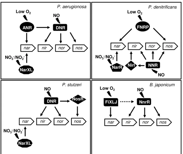
Figure 1.3 - Gene regulation of the denitrification pathway in response to nitrate/nitrite, low O2
and nitric oxide. The regulatory network is based on the current knowledge of regulation of denitrification from P. aeruginosa, P. denitrificans, P. stutzeri and B. japonicum. Positive
regulation is indicated by solid arrows and indirect regulation is indicated by dashed arrows. Adapted from 47. ... 9
Figure 1.4 - Organization of nos gene clusters of selected genomes of Gram-negative (α-,β-,γ- and
ɛ-subdivision) and Gram-positive bacteria representing the two clades. PA – gene encoding a
pseudoazurin, Az - gene encoding an azurin, TM - transmembrane protein, C - protein containing
either a c-type heme motif (CXXCH) or a CXXC motif, FeS-protein contain a Fe-S motif, dnr -
dissimilative nitrate respiration regulator, tat - twin-arginine translocation. Undesignated genes are
represented in white. ... 12
Figure 1.5 - Comparison of primary sequence alignment of N2ORs from clade I and clade II. Clade
I N2OR is from γ-proteobacteria Pseudomonas stutzeri A1501 (Ps) and clade II N2OR is from
ɛ-proteobacteria Wolinella succinogenes (Ws). TAT- and Sec-motifs are underlined and the start of
mature protein is identified with a square. Clade I and clade II CuZ binding motifs are highlighted on black filled rectangles. The c-type heme binding motif is highlighted in bold. Vertical lines,
colons or stops below the sequence indicate matches, high conservation or conservation of the residues, respectively. ... 13
Figure 1.6 - Model of N2OR biogenesis in P. stutzeri. Apo-NosZ as a dimer is exported to the
periplasm by Tat translocon. The copper may enter to the periplasm by a transporter not encoded by the nos operon and also possibly through NosA. ScoP and NosL are putatively involved in the
copper assembly. Sulfur is putatively provided by NosDFY. NosX is involved in the biosynthesis of NosR flavin center. NosR is essential to N2OR activity and may provide electrons. Each protein
xvi
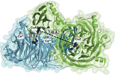
subunit. One monomer is represented in blue and the other in green, with the C-terminal dark colored and the N-terminal light colored. The copper atoms are represented as dark blue spheres and the sulfur atoms are represented as yellow spheres. The calcium ions in the dimer are evidenced as grey small spheres, being the two Ca2+ of the monomer labeled. The distance between CuA center and “CuZ centers” is represented. Figure was prepared with DS visualizer 4.5 using PDB ID: 1QNI. ... 17
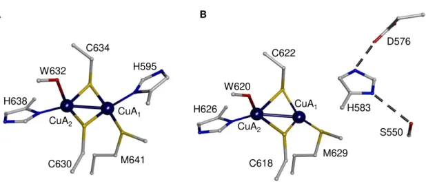
Figure 1.8 - Structures of CuA center of N2OR. Representation of the CuA center of (A)
P. denitrificans N2OR and (B) P. stutzeri N2OR. In Panel B, H583 does not coordinate CuA1 atom.
The copper atoms are represented as blue dark spheres and numbered 1-2. Figure was prepared with DS visualizer 4.5 using PDB ID: 1FWX (A) and 3SBP (B). The residues were numbered according to the primary sequence of N2OR in each microorganism. ... 20
Figure 1.9 - Structures of the “CuZ center” of N2OR. (A) Representation of the CuZ*(4Cu1S)
from P. denitrificans N2OR with the first and second coordination sphere residues. This form
contains one sulfur atom named S1 and one oxygen atom (from either a hydroxide or a water
molecule) at the CuI-CuIV edge. (B) Representation of the “CuZ center” as CuZ(4Cu2S) from P. stutzeri N2OR with first and second coordination sphere residues. This form contains two sulfur
atoms named S1 and S2. The copper atoms are represented as dark blue spheres and numbered I-IV.
The residues are numbered according to the primary sequence of each N2OR. Figure was prepared
with DS visualizer 4.5 using PDB ID: 1FWX (A) and 3SBP (B). ... 23
Figure 1.10 - Substrate binding mode in N2OR. (A) The N2O was modeled in the CuI-CuIV edge in
a µ-1,3-bridging mode. The N2O binding site was proposed for A. cycloclastes N2OR structure, based on DFT calculations and spectroscopic features of the “CuZ center” as CuZ*(4Cu1S), in the [4Cu1+] oxidation state. (B) The N
2O molecule is located between CuA and “CuZ” centers. P. stutzeri crystals of N2OR, with the “CuZcenter” as CuZ(4Cu2S), in the [2Cu2+-2Cu1+] oxidation
state, were pressurized with N2O. The surface at the dimer interface, as well as the relevant residues
involved in the substrate binding mode are represented and colored according to the monomer by green and blue. The N2O atoms are colored according to the element. The residues are numbered
according to their primary structure. Figures were prepared using DS visualizer 4.5, using PDB ID: 2IWF (A) and 3SBR (B). ... 28
Figure 2.1 - Kinetic traces of N2O and NO reduction assay by whole-cells, using methyl viologen
as electron donor. In the assays, 40 µL of M. hydrocarbonoclasticus cell suspension (in a total
volume of 1 mL) were added to a solution containing 100 µM (in the case of N2O assay) or
120 µM (in the case of NO assay) of reduced methyl viologen in 100 mM Tris-HCl pH 7.6, followed by addition of (A) 1.25 mM N2O-saturated water or (B) 9.6 µM NO-saturated water. The
arrows indicate the addition point of cells and substrates. ... 42
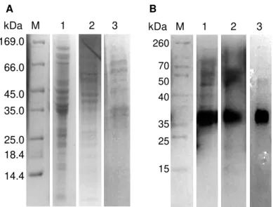
Figure 2.2 - SDS-PAGE (12.5 % polyacrylamide) analysis of periplasmic fractions obtained from
M. hydrocarbonoclasticus growths in bioreactor at different pH values, Coomassie blue stained (A)
and heme stained (B). Lanes M - marker, 1 – growth at pH 6.5, 2 – growth at pH 7.5, 3 – growth at pH 8.5. The gels were run for 1 h at 150 V. ... 48
Figure 2.3 - SDS-PAGE (12.5 % polyacrylamide) of the fractions obtained after each
chromatographic step of N2OR purified under anoxic conditions, from a M. hydrocarbonoclasticus
xvii
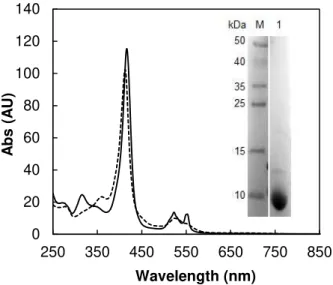
Figure 2.4 - UV-visible spectra of cytochrome c552(3.6 μM) as prepared (dashed line) and reduced
with sodium ascorbate (solid line). Insert: SDS-PAGE (12.5 % polyacrylamide) of the purified cytochrome c552 (lane 1), stained with Coomassie blue. ... 50
Figure 2.5 –Specific activity of N2OR, with 65 % of “CuZ center” as CuZ*(4Cu1S), as a function
of incubation time with reduced MV as electron donor. N2OR (70 nM) from M. hydrocarbonoclasticus was incubated in the presence of 100 μM MV and 50 μM sodium
dithionite in 100 mM Tris-HCl pH 7.6. Each reaction was initiated by the addition of 1.25 mM N2O-saturated water and followed at 600 nm. ... 53
Figure 2.6 - Example of steady-state kinetic traces of N2OR using reduced MV as electron, with its
oxidation followed at 600 nm. The reactions were initiated by the addition of 1.25 mM N2O-saturated water. The arrows indicate the addition point of N2OR and N2O. Kinetic traces with
pre-activated N2OR are represented by a solid line and traces with N2OR without prior incubation
by a dashed line. ... 53
Figure 2.7 - Example of steady-state kinetic traces of N2OR in the presence of physiological redox
donor (cytochrome c552), followed at 552 nm. (A) Activity assay initiated by 70 nM activated
N2OR, with 90 % of “CuZ center” as CuZ*(4Cu1S), in a cuvette containing 1.25 mM N2O and 10
µM cytochrome c552. (B) Activity assay initiated by dithionite-reduced N2OR, with 10 % of “CuZ center” as CuZ*(4Cu1S) in a cuvette containing 1.25 mM N2O and 7 µM cytochrome c552. Insert:
Absorbance in the initial seconds (20 - 220 s) evidencing the addition of N2OR. The arrows
indicate the addition of N2OR, cytochrome c552and N2O. ... 55
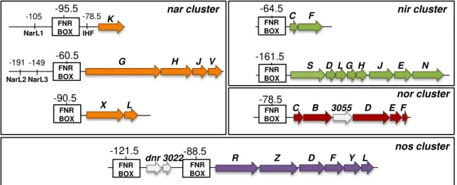
Figure 3.1 - Arrangement of denitrification genes in the genomic region 3087251-3163109 of
M. hydrocarbonoclasticus ATCC 49840. Genes belonging to the nitrate reductase (nar), nitrite
reductase (nir), nitric oxide reductase (nor) and nitrous oxide reductase (nos) clusters are colored in
orange, green, red and purple, respectively. The catalytic subunit of each cluster is light colored. Unidentified genes are white colored and the dnr and nnrS regulator genes are colored in dark grey.
The number below each gene is the MARHY gene identification. Our own in silico analysis
indicates that MARHY3057 and MARHY3058 are putative norE and norF homologues,
respectively. Arrows show the direction of transcription. ... 70
Figure 3.2 - Identification and analysis of putative FNR and NarL binding sites in nitrate reductase
(nar), nitrite reductase (nir), nitric oxide reductase (nor) and nitrous oxide reductase (nos) gene
clusters, involved in gene regulation. A putative FNR box was also identified upstream the dnr
gene, located upstream nos gene cluster. The centered position of FNR, NarL and IHF sites relative
to the ATG site is indicated. The matching of motifs with the consensus sequence and their scores are provided in Supplementary Information (S1)... 73
Figure 3.3 - M. hydrocarbonoclasticus growth curves in serum flasks under microaerobic
xviii
in the secondary axis. The growth curves are represented as Log OD600nm (open symbols). Nitric
oxide reduction by the whole-cells was not determined in the growth performed at pH 6.5. ... 75
Figure 3.4 - Growths of M. hydrocarbonoclasticus in a 2 L bioreactor under microaerobic
conditions at different pH values. Representative (A) growth profile and (B) oxygen profile measured during the growth. Growths were performed at pH 6.5 (filled diamonds), pH 7.5 (filled circles) and pH 8.5 (open triangles). ... 76
Figure 3.5 - Expression of narG (orange diamonds), nirS (green squares), c-norB (filled red
triangles), q-norB (open red triangles) and nosZ (purple circles) encoding the catalytic domains of M. hydrocarbonoclasticus denitrification enzymes during 20 h for the growths performed at (A) pH
6.5, (B) pH 7.5 and (C) pH 8.5. Relative expression values were obtained by normalizing expression of each target gene relative to the control housekeeping gene 16S rRNA, as described in Materials and Methods (Section 2.6.2)... 78
Figure 3.6 - Comparative gene expression of nosZ/nirS (white bars) and nosZ/norB (black bars) at
pH 6.5, 7.5 and 8.5, at the time-point of maximum expression levels in the biological replicates. Relative expression values were obtained by normalizing expression of each target gene to the control housekeeping gene 16S rRNA. ... 79
Figure 3.7 - Putative regulatory network controlling the denitrification genes in
M. hydrocarbonoclasticus. The main signals involved in the regulation of nar, nir, nor and nos
gene clusters are the low oxygen tensions, nitric oxide and nitrate. Two levels of regulation were postulated for nar cluster transcription through the FNR-like and the two-component system
NarXL (histidine kinase and response regulator) in response to low oxygen and nitrate levels, respectively. The regulatory protein FNR is also involved in DNR activation. DNR responds to nitric oxide (first produced by the initial low levels of nitrite reductase) and regulates the expression of nir, nor and nos gene clusters. Our own bioinformatic analysis suggests that
MARHY0862 and MARHY3023 are, respectively, the FNR and DNR homologues involved in regulation of the denitrification genes in M. hydrocarbonoclasticus. Dashed arrows indicate the
putative but lower level of nir, nor and nos gene regulation by FNR. ... 80
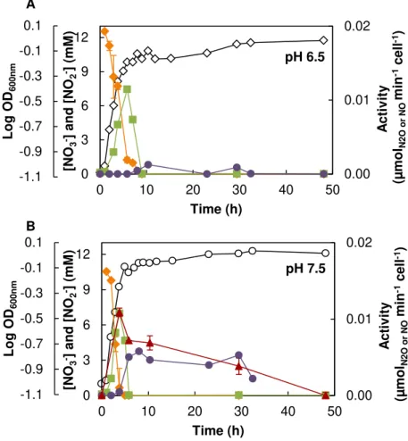
Figure 3.8 - Representative profile of M. hydrocarbonoclasticus denitrification metabolites and
enzymatic activities at (A) pH 6.5, (B) pH 7.5 and (C) pH 8.5. Nitrate (orange diamonds) and nitrite (green squares) concentrations are represented in the primary axis and nitric oxide (red triangles), and nitrous oxide (purple circles) reduction by the whole-cells are represented in the secondary axis. ... 82
Figure 3.9 - Heme stained SDS-PAGE (12.5 % polyacrylamide gel) analysis of cells of
M. hydrocarbonoclasticus grown in the bioreactor under microaerobic conditions in the presence of
nitrate. Lanes A, B and C are the total extract obtained from the growth at pH 6.5, 7.5 and 8.5, respectively, normalized for an amount of cells (0.24 g cells mL-1). The protein band corresponding
to cd1NiR is identified in the gel. ... 83
Figure 3.10 - Kinetic activity for the reduction of N2O by the whole-cells of
M. hydrocarbonoclasticus grown under microaerobic conditions in the presence of nitrate at pH
xix
Figure 3.11 - Analysis of the transcriptional organization of M. hydrocarbonoclasticus nos gene
cluster. (A) PCR products of intergenic regions between nosR-nosZ (a, lanes 1-3), nosZ-nosD (b,
lanes 4-6) and nosD-nosL (c, lanes 7-9) using cDNA (lanes 1, 4, 7), RT (minus) control reaction
(lanes 2, 5, 8) and genomic DNA (3, 6, 9). (B) Genomic organization of nos gene cluster in the
genome of M. hydrocarbonoclasticus. The gene encoding for N2OR is colored in black. ... 86
Figure 3.12 - Expression of nosR (filled diamonds), nosD (filled squares), MARHY1380 (open
circles) and MARHY1479 (open triangles) encoding accessory proteins involved in biosynthesis of
N2OR from M. hydrocarbonoclasticus during 20 h, for the growths performed at (A) pH 6.5, (B)
pH 7.5 and (C) pH 8.5. Relative expression values were obtained by normalizing expression of each target gene to the control housekeeping gene 16S rRNA, as described in Materials and Methods (Section 2.6.2). ... 87
Figure 3.13 - Expression of nosL (open triangles), senC (open circles), MARHY1049 (filled
squares) encoding M. hydrocarbonoclasticus denitrification enzymes during 20 h for the growths
performed at (A) pH 6.5 and (B) pH 7.5. Relative expression values were obtained by normalizing expression of each target gene to the control housekeeping gene 16S rRNA, as described in Materials and Methods (Section 2.6.2). ... 88
Figure 3.14 - 2D profile of the membrane fraction (80 µg) of M. hydrocarbonoclasticus cells
grown under microaerobic conditions in the presence of nitrate (10 mM) at (A) pH 6.5 and (B) pH 7.5. Differential expression is indicated by black circles, being the spots selected based on a differential expression fold > 2 with p-values ≤ 0.05 between two biological replicates. For the 1st
dimension the samples were applied on 7 cm IPG strips (pH range 4-7) and in the 2nd dimension the
IPG strips were applied in a 10 % polyacrylamide SDS-PAGE, further stained with colloidal Coomassie blue. The spot identify by MS is marked with an asterisk. ... 90
Figure 3.15 - Coomassie blue stained SDS-PAGE (12.5 % polyacrylamide) analysis of N2OR
purified from the growths performed in the bioreactor at different pH. Lanes M, 1, 2, 3 and 4 are the protein marker, N2ORpH6.5, N2ORpH7.5, N2ORpH8.5 and Anaer7.5,respectively. ... 92
Figure 3.16 - Visible spectra of M. hydrocarbonoclasticus N2OR isolated from cells grown at (A)
pH 6.5, N2ORpH6.5, (B) pH 7.5, N2ORpH7.5 and (C) pH 8.5, N2ORpH8.5,in 100 mM Tris-HCl pH 7.6.
In each panel is presented the spectra of potassium ferricyanide fully oxidized (I – solid line), sodium dithionite-reduced (II - dashed line), as-isolated (III – dashed-dotted line) and sodium ascorbate-reduced (IV – dotted line) states. In panel C, spectrum II is contaminated with cytochromes and thus this spectrum is only presented from 560 nm. Extinction coefficient is reported relative to the monomer. ... 94
Figure 3.17 - X-band EPR spectra of M. hydrocarbonoclasticus N2OR isolated from growths
performed at different pH values: (A) N2ORpH6.5, (B) N2ORpH7.5 and(C) N2ORpH8.5. In each panel
the spectra of oxidized (I), sodium ascorbate reduced (II), sodium dithionite reduced (III) and methyl viologen reduced (IV) are represented. The instrument settings for the acquisition were: microwave frequency, 9.65 GHz; microwave power, 2 mW; gain, 1x10⁵; temperature, 30 K. The
xx
3 h at different pH values at RT. Data were fitted with a bell-shaped curve, and pKa values of
7.5 ± 0.2 and 9.7 ± 0.1, with optimum activation at pH ~ 8.5. ... 107
Figure 4.2 - Effect of pH on lysine residue (K447) in the vicinity of CuZ*(4Cu1S) center. ... 108
Figure 4.3 - Specific activity of N2OR with 20 % of “CuZ center” as CuZ*(4Cu1S) during dialysis
against 50 mM Tris-HCl 7.6 (filled circles) and 50 mM CHES pH 9.7 (open circles). The specific activities were measured at 0 h (without incubation with reduced methyl viologen) in 100 mM Tris-HCl pH 7.6. ... 109
Figure 4.4 - Visible spectra of M. hydrocarbonoclasticus N2OR with 20 % of “CuZ center” as
CuZ*(4Cu1S). (A) As-isolated N2OR, in [1Cu2+-3Cu1+] state, (dashed line) and dialyzed against
50 mM CHES pH 9.7, after 14 h (dotted line) and after 24 h (solid line). (B) Potassium ferricyanide oxidized spectra of N2OR after 24 h of dialysis at pH 9.7 (solid bold line) and prior to
the assay (dashed-dotted line) are represented. Absorbance was corrected to the total protein concentration. The asterisk indicates a small contamination with a cytochrome. ... 110
Figure 4.5 - Spectra of different forms of M. hydrocarbonoclasticus N2OR used to produce
crystals, being N2ORpH6.5, with 90 % of “CuZ center” as CuZ*(4Cu1S) (dashed line) and N2ORpH7.5, with 17 % of “CuZ center” as CuZ*(4Cu1S) (solid line), in 100 mM Tris-HCl pH 7.6... 111
Figure 4.6 - Crystals of different forms of N2OR from M. hydrocarbonoclasticus. (A) Blue crystals
were obtained from the preparation with 90 % of “CuZ center” as CuZ*(4Cu1S), purified from a growth carried out at pH 6.5 and (B) purple crystals were obtained from a 17 % of “CuZ center” as CuZ*(4Cu1S) preparation purified from a growth performed at pH 7.5. ... 111
Figure 4.7 - Structure of asymmetric unit of the purple crystal. In each dimer, the monomers are
differently colored. One of the dimer has the surface evidenced, as well as the CuA and CuZ(4Cu2S) centers, which are represented by spheres, being copper atoms represented by blue spheres and sulfur atoms represented by yellow spheres. CuA and “CuZ” centers of a monomer are identified. Figure was prepared with DS Visualizer 4.5. ... 112
Figure 4.8 – Stereo representation of Ca2+ (green sphere) and K+ (purple sphere) binding sites in
the M. hydrocarbonoclasticus N2OR structure obtained for the purple crystal at 1.9 Å. One
monomer of N2OR is colored according to the secondary structure, while the other is colored in
grey. Copper and sulfur atoms are represented as blue and yellow spheres, respectively. The CuA center is part to the monomer colored in grey, while “CuZ center” belongs to the other monomer. Figure was prepared with Pymol. ... 114
Figure 4.9 –Structure of purple crystal of M. hydrocarbonoclasticus N2OR. (A) Representation of
the backbone with one of the monomers highlighted, and colored according to the secondary structure. The CuA and CuZ(4Cu2S) centers are represented by spheres, being copper atoms represented by blue spheres and sulfur atoms represented by yellow spheres. (B) Surface is colored according to Eisenberg hydrophobicity scale (highly hydrophobic residues are colored in red). CuA center region is identified with a dashed circle. Figure was prepared with Pymol. ... 115
Figure 4.10 – Primary sequence alignment of N2ORs whose structure have been deposited in the
xxi
the intermolecular electron transfer are highlighted in red, and those of the intramolecular electron transfer are identified with a pink box (pathway 1) and with a brown box (pathway 2). Residues highlight at green and violet coordinate the calcium and the potassium ions, respectively. Residues highlight in orange are involved in re-orientation of N2O molecule. The tat-motif is underlined and
the start of mature proteins is identified with a black square. Bacterial species are identified by: Mh
–Marinobacter hydrocarbonoclasticus, Ps–Pseudomonas stutzeri, Pd–Paracoccus denitrificans, Ac – Achromobacter cycloclastes and Sd – Shewanella denitrificans. Asterisks, colons or stops
below the sequence indicate identity, high conservation or conservation of the amino acids, respectively. ... 116
Figure 4.11 – Representation of the interface region between the functional dimer colored by
Eisenberg hydrophobicity (the most hydrophobic residues are colored in red) in the structure of
M. hydrocarbonoclasticus N2OR with 17 % of “CuZ center” as CuZ*(4Cu1S). Hydrophobic residues in this region form a channel for the access of the substrate to the “CuZ center”. The re-orientation of the N2O molecule is through M620 and F614 residues. Figure was prepared with
Pymol. ... 118
Figure 4.12 – Difference electron density maps for the “CuZ center” in a sample with 90 % of
“CuZ center” as CuZ*(4Cu1S) (A) and 17 % of “CuZ center” as CuZ*(4Cu1S) (B). The coppers and sulfur atoms are represented by blue and yellow spheres, respectively. In panel (A) electron density map 2F0-Fc is contoured at 3.0 σ (blue) and the F0-Fc electron density map calculated is
contouring at -1.5 σ level (red). In panel (B) electron density map 2F0-Fc is contoured at 1.0 σ
(blue) and the F0-Fcelectron density map calculated is contouring at 3.0 σ level (purple). F0 and Fc
are the observed and calculated structure factors, respectively. Difference electron density maps were generated by Fast Fourier Transform (CCP4: Supported program) and the figures were prepared with Pymol. ... 119
Figure 4.13 – Potentiometric redox titration of N2OR, with 15 % of “CuZ center” as
CuZ*(4Cu1S), performed at pH 7.6. The CuA (diamonds) and the CuZ(4Cu2S) (circles) centers were followed by visible spectroscopy at 800 and 660 nm, respectively. For both centers the absorbance was monitored in the reductive (filled symbols) and oxidative (open symbols) titration. The titration of each center was fitted to one-electron process using the Nernst equation, with a Em,7.6 = + 272 ± 10 mV (vs SHE) for CuA center and a Em,7.6 = + 65 ± 10 mV (vs SHE) for
CuZ(4Cu2S) center. The insert is an example of the bands followed in the visible spectra, being the oxidation and reduction process represented by solid bold and dashed arrows, respectively. ... 121
Figure 4.14 – pH dependence of the reduction potentials of CuA center at 20 °C. The
potentiometric redox titrations were followed by visible spectroscopy at 480 nm in a N2OR sample with 50 % of “CuZ center” as CuZ*(4Cu1S). Data obtained were fit (solid line) by a linear regression: y = - 54.2x + 652.8, R2 = 0.987. ... 122
Figure 4.15 – pH dependence of the reduction potential of N2OR, with 15 % of “CuZ center” as
xxii
caused by an unreached equilibrium during the oxidation. ... 123
Figure 4.16 – Scheme illustrating the possible microstates of the CuZ(4Cu2S) center of
M. hydrocarbonoclasticus N2OR. The hexagons represent the CuZ(4Cu2S) center, which can be
oxidized (open hexagons) or reduced (filled hexagons). The protonated (dashed circles) and deprotonated (solid circles) microstates are grouped according its oxidation potential, being P0 and
P0H representing the oxidized and oxidized protonated microstates, and P1 and P1H representing
the reduced and reduced protonated microstates, respectively. ... 124
Figure 4.17 – Cyclic voltammograms of 200 µM of N2OR with 60 % of “CuZ center” as
CuZ*(4Cu1S), immobilized onto a MWCNTs layer coated on a glassy carbon electrode, in 100 mM potassium phosphate pH 7.0 at a scan rate of 10 mV s-1. Dashed line represents the
MWCNTs layer prior to enzyme immobilization and solid line voltammogram was obtained after N2OR immobilization. The arrow represents the direction of the scan. Signal Ia and signal Ic,
represents the anodic and cathodic peak of signal I and signal IIa and IIc represents the anodic and cathodic peak of signal II. ... 127
Figure 4.18 –Cyclic voltammograms (5 ≤ v≤ 100 mV s-1) of 200 µM of N2OR with 60 % of “CuZ
center” as CuZ*(4Cu1S), immobilized onto a MWCNTs layer (7 µL) coated on a glassy carbon electrode, in 100 mM potassium phosphate pH 7.0. ... 128
Figure 4.19 – Electrochemical behavior (5 ≤ v ≤ 100 mV s-1) of 200 µM of N2OR with 60 % of
“CuZ center” as CuZ*(4Cu1S), immobilized onto a MWCNTs layer coated on a glassy carbon electrode, in 100 mM potassium phosphate pH 7.0. In panel (A) is presented the dependence of anodic (filled symbols) and cathodic (open symbols) peaks currents with the scan rate. Circles showed a linear dependence, with linear regressions: y = 0.13x + 0.17, R2 = 0.969 and
y = 0.12x - 0.11, R2 = 0.995, for the anodic and cathodic peaks currents, respectively. Triangles
show a different behavior. In panel (B) the potential of the cathodic counterpart of signal II is represent as a linear dependence with log of scan rate, for v > 20 mV s-1. Linear regression:
y = 162.39x + 216.42, R2 = 0.985. ... 129
Figure 4.20 – Differential pulse voltammograms (tp = 100 ms) of different forms of N2OR
immobilized onto a MWCNTs layer coated on a glassy carbon electrode, in 100 mM potassium phosphate pH 7.0. In panel (A) DP voltammogram was acquired for 174 µM of N2OR with 90 % of “CuZ center” as CuZ*(4Cu1S) and in panel (B) DP voltammogram was acquired for 132 µM of N2OR with 17 % of “CuZ center” as CuZ*(4Cu1S). ... 130
Figure 4.21 –Dependence of pH on the reduction potentials of signal I (filled symbols) and signal
II (open symbols) of different forms of N2OR observed by cyclic voltammetry at 20 mV s-1. In
panel (A) N2OR with 90 % of “CuZ center” as CuZ*(4Cu1S) with signal I showing a linear
regression y = -55.2x + 772.4, R2 = 0.998 and signal II with a linear regression y = -57.4x + 494.3,
R2 = 0.995. In panel (B) a N
2OR sample with 10 % of “CuZ center” as CuZ*(4Cu1S) was used,
being the linear regressions y = -55.4x + 773.9, R2 = 0.995 and y = -57.4x + 464.7, R2 = 0.991
determined for signal I and II, respectively. ... 131
Figure 4.22 – Electrocatalytic peak current of activated N2OR with 60 % of “CuZ center” as
CuZ*(4Cu1S), in 100 mM potassium phosphate buffer pH 7.0. Different amounts of N2O-saturated
xxiii
0.45 mM of water-saturated N2O (solid line) obtained at the scan rate of 20 mV s-1. ... 132
Figure 4.23 – Cyclic voltammograms of cytochrome c552 with as-isolated N2OR with 60 % of
“CuZ center” as CuZ*(4Cu1S), in 100 mM potassium phosphate buffer at pH 7.0, obtained at 10 mV s-1. The voltammograms of cytochrome
c552 (140 µM)in the presence of an equimolar ratio
of N2OR (solid line) and upon addition of 2 mM N2O (dashed line) are presented. The arrow
represents the direction of the scan. ... 133
Figure 4.24 – Scheme for N2OR mediated catalysis: cytochrome c552 is reduced by the gold
electrode and rapidly oxidized by electron transfer to N2OR, which in turn is re-oxidized by
reduction of N2O to N2. ... 134
Figure 5.1 – Reduction of 16.5 µM N2OR, with 80 % of “CuZ center” as CuZ*(4Cu1S), in the
presence of 7.5 mM (~ 400 equivalents) sodium ascorbate. (A) Visible spectra during the reduction of oxidized N2OR, by sodium ascorbate. Representation of spectra acquired every 1 min. The
arrow represents the direction of the spectral changes at 482 nm and the asterisk represents the absorbance at 653 nm. (B) Time dependence of reduction of CuA center (red) at 482 nm and CuZ*(4Cu1S) (blue) at 653 nm. The absorbance was normalized and fitted (solid dashed line) using kinetics Tenua program with k1 = k2 = 1.4 M-1 s-1 and kIET < 1×10⁻⁵ s-1, R2 = 0.993. ... 140
Figure 5.2 – Reduction of 17 µM N2OR, with 10 % of “CuZ center” as CuZ*(4Cu1S) in the
presence of 7.5 mM (~ 400 equivalents) sodium ascorbate. (A) Visible spectra during reduction of oxidized N2OR, in the presence of sodium ascorbate, collected during 800 s. Representation of
spectra acquired with 1 min intervals. The arrows indicate the direction of the changes in the spectra at 485 nm (dark blue), 550 nm (purple) and 785 nm (light blue). (B) Time dependence of reduction of CuA center (dark blue) and CuZ(4Cu2S) (purple). The absorbance was normalized and fitted (solid dashed line) using kinetics Tenua program with k1 = k2 = 1 M-1 s-1 and kIET < 1×10⁻⁵
s-1, R2 = 0.914. Normalized absorbance at 482 nm and 785 nm are fitted with similar parameters.
... 141
Figure 5.3 –Normalized time dependence of reduction of CuA center of 20 µM N2OR with 60 %
of “CuZ center” as CuZ*(4Cu1S) in the presence of 0.5 mM sodium ascorbate (dark blue) and in the presence of 5 µM DAD and 0.5 mM sodium ascorbate (light blue). Absorbance was determined at 482 nm. Kinetics were fitted using Tenua program, with k1 = k2 = 6 M-1 s-1 and kIET < 1×10⁻⁶ s-1,
R2 = 0.957, for the assay performed in the absence of DAD, and
k1 = k2 = 28 M-1 s-1 and kIET < 1×10⁻⁵ s-1, R2 = 0.995, when 5 µM DAD was added to the experiment. ... 143
Figure 5.4 –CuZº formation and decay, obtained from 20 µM fully reduced N2OR, with 60 % of
“CuZ center” as CuZ*(4Cu1S), after reaction with 30.5 µM N2O. (A) Visible spectra of CuZº
decay (solid bold arrow) and formation of a new species at 617 nm (dashed arrow) during 2500 s of the reaction. The arrows indicate the direction of spectral changes. (B) Normalize time dependence at 683 nm (filled diamonds) and at 617 nm (open circles). The data were fitted (dashed black line) to a single exponential, using kdecay = 1.8 ×10⁻³ s-1, R2 = 0.985. ... 144
Figure 5.5 – Changes at the maximum absorption band of “CuZ center” after formation of CuZ°
(reaction of 22 µM N2OR, with 60 % of “CuZ center” as CuZ*(4Cu1S), with 24 µM N2O). (A)
xxiv
corresponded to the absorbance observed for each of the wavelengths showed in A. Reaction performed in 100 mM potassium phosphate at pH 7.6. ... 145
Figure 5.6 – Reactivity of 22 µM fully reduced N2OR, with 60 % of “CuZ center” as
CuZ*(4Cu1S), with 24 µM N2O for 2500 s followed by oxidation with potassium ferricyanide. (A)
Visible spectrum of CuZº collected after 14 s (dotted line) and after 2500 s of the addition of N2O
(long dashed line) and potassium ferricyanide oxidation (solid line) at the end of the reaction. (B) Visible spectrum of oxidation (solid line) at the end of reaction (another preparation similar as solid line spectra showed in A), the same oxidized spectrum but recorded after 3 days of oxygen exposure (dashed-dotted line) and the oxidized spectrum of N2OR prior to the experiment (dashed
line) are presented. ... 146
Figure 5.7 – Visible spectra of 20 µM fully reduced N2OR, with 80 % of “CuZ center” as
CuZ*(4Cu1S), over 2500 s in the presence of sodium ascorbate (~ 400 fold excess). (A) The fully reduced spectra of N2OR after 0 s and 2500 s are presented in grey and black, respectively.
Oxidation with increasing concentrations of potassium ferricyanide after 2500 s is represented by blue gradient color, being the darker spectra the one with highest concentration of potassium ferricyanide. (B) The spectra of oxidized, sodium ascorbate reduced and sodium dithionite reduced are colored in blue, light green and dark green, respectively. The spectrum of CuZ*(4Cu1S) reduced with dithionite was provided for comparison, represented by black dashed line. The arrows indicate the direction of spectra with increasing concentration of reducing agents. Ox – oxidation, Red - reduction. ... 147
Figure 5.8 –Spectra 14 s after formation of CuZ° at pH 6.0 (red), 7.6 (black), 8.5 (green) and 9.7
(blue). Absorbance was subtracted to the amount of CuZ(4Cu2S) present in each sample. ... 148
Figure 5.9 –Reaction of fully reduced N2OR with stoichiometric amount of N2O and formation of
“intermediate 2” of the catalytic cycle. ... 149
Figure 5.10 –Spectra 2500 s after CuZ° formation at pH 6.0 (red), 7.6 (black), 8.5 (green) and 9.7
(blue). Spectra were corrected for the total amount of protein by Pierce 660nm protein assay. .... 150
Figure 5.11 –Pathways of CuZ' formation and mechanism of N2O reduction. CuZ' can be obtained
by oxidation of fully reduced N2OR or by decay of intermediate CuZ°. ... 151
Figure 5.12 – Normalized time dependence of the absorbance at 617 nm, at pH 6.0 (filled
triangles), 7.6 (filled diamonds), pH 8.5 (open squares), pH 9.5 (crosses) and pH 9.7 (open circles). ... 152
Figure 5.13 –Reduction of CuZº (formed by reaction of 20 µM fully reduced N2OR, with 80 % of
“CuZ center” as CuZ*(4Cu1S), with 36 µM N2O) in the presence of 7.3 mM (~ 400 equivalents)
sodium ascorbate, added 37 s after N2O addition. (A) Visible spectra of reduction of CuZº in the
first reactivity phase. Representation of spectra acquired every 0.5 min. The spectrum of N2OR as
CuZº collected 14 s after N2O addition is represented by a dashed line and the arrows indicate the
xxv
sodium ascorbate, added 37 s after N2O addition. Normalized time dependence of CuA center
reduction at 482 nm (filled circles) and CuZº reduction at 683 nm (open triangles): (A) Fit for an IET kinetic model, using kred1 = kred2 = kred3 = 1.4 M-1 s-1; kdecay = 1.8×10⁻³ s-1; kIET = 0.1 s-1 and kIET/k IET = 1.1; R2 = 0.983. (B) Fit for the direct reduction of CuZº by sodium ascorbate, using kred1 = kred2 = kred3 = 1.4 M-1 s-1; kdecay = kdecay = 1.8×10⁻³ s-1; kZº = 0.6 M-1 s-1; R2 = 0.952. Note that
correlation coefficients were determined for the CuZº fitting. Fit of CuA center reduction is represented by solid line and the CuZº reduction is represented by dashed line. ... 156
Figure 5.15 –Fitting of the reduction of CuA center (filled circles) and CuZº (open triangles) in a
reaction of 20 µM N2OR with 80 % of “CuZ center” as CuZ*(4Cu1S) with 36 µM N2O, by sodium
ascorbate (7.3 mM). The absorbance was normalized and fitted for CuA center at 482 nm (solid line) and CuZº at 683 nm (dashed line) with the two models described, using kinetics Tenua program. (A) Fit for an IET kinetic model, using kred1 = 0.9 M-1 s-1; kred2 = kred3 = 1.4 M-1 s-1; kdecay = 1.8×10⁻³ s-1; kIET = 0.1 s-1 and kIET/k-IET = 2.5; R2 = 0.998. (B) Fit for the direct reduction of
CuZº by sodium ascorbate, using kred1 = 0.17 M-1 s-1; kred2 = kred3 = 1.4 M-1 s-1; kdecay = kdecay =
1.8×10⁻³ s-1;
kZº = 0.6 M-1 s-1; R2 = 0.993. ... 157
Figure 5.16 –Kinetic model of the CuZº reduction by IET through CuA center using the Scheme
5.3. Each line represents a different species, being those containing the CuA center oxidized represented by solid lines and those with the CuA center reduced by dashed lines. The “CuZ center” as CuZº, fully reduced form and resting state are colored by green, grey and red, respectively. The model was generated in the kinetics Tenua software using the following kinetic parameters: kred1 = 0.9 M-1 s-1; kred2 = kred3 = 1.4 M-1 s-1; kdecay = 1.8×10⁻³ s-1; kIET = 0.1 s-1 and kIET/k IET = 2.5; [N2OR] = 20 µM; [Asc] = 7.29 mM. ... 158
Figure 5.17 –Reduction of CuZº, obtained when 30 µM fully reduced N2OR with 60 % of “CuZ
center” as CuZ*(4Cu1S) reacted with 32 µM N2O, by 490 µM (~ 16 equivalents) sodium
ascorbate, added 30 s after N2O addition. (A) Visible spectra of reduction of CuZº and CuA during
3000 s. The arrows indicated the direction on spectra changes with time, at 482 nm (solid bold arrow) and 683 nm (dashed arrow). (B) Fitting adjustment of reduction of CuA center (filled circles and solid line) and CuZº (open triangles and dashed line) for an IET kinetic model, using
kred1 = 3 M-1 s-1; kred2 = kred3 = 6 M-1 s-1; kdecay = 1.8×10⁻³ s-1; kIET = 0.01 s-1 and kIET/k-IET = 2.5;
R2 = 0.998. Note that correlation coefficients were determined for the CuZº fitting. ... 158
Figure 5.18 – Reaction of 30 µM fully reduced N2OR, with 60 % of “CuZ center” as
CuZ*(4Cu1S), with 10 mM of sodium ascorbate (~ 330 fold-excess) and 200 µM N2O. (A) Visible
spectra acquired during 3000 s. The arrow indicated the direction of changes over time. (B) Time dependence absorbance of CuZº at 683 nm (open circles), CuZ*(4Cu1S) at 640 nm (filled squares) and CuZ' intermediate at 620 nm (filled triangles). ... 160
Figure 5.19 – Mechanism of activation and proposed catalytic cycle of N2OR from
M. hydrocarbonoclasticuswith “CuZ center” as CuZ*(4Cu1S)... 161
Figure 6.1 – Effect of halides in the visible spectra of 12 µM oxidized N2OR with 50 % of “CuZ
xxvi
arrows indicate the direction of the spectral changes. Spectra were corrected for the absorbance at 402 nm. ... 168
Figure 6.2 –Variation of the absorbance at 640 nm upon addition of (A) chloride and (B) iodide to
N2OR with 50 % of “CuZ center” as CuZ*(4Cu1S), at pH 7.6. Data were fitted to one binding site
equation with a Kdapp of 34 ± 2 mM and 40 ± 2 mM, for the binding of chloride and iodide,
respectively. ... 169
Figure 6.3 –Effect of pH on the iodide binding to 12 µM oxidized N2OR with “CuZ center” as 50
% CuZ*(4Cu1S): (A) pH 6.0, (B) pH 7.6 and (C) pH 9.0. The spectra with 0 mM (dashed line) and 200 mM (solid line) are represented for each pH. Spectra were corrected to 399 nm. ... 170
Figure 6.4 –Effect of halides on the visible spectra of 18 µM oxidized N2OR with 10 % of “CuZ
center” as CuZ*(4Cu1S), in 100 mM Tris-HCl, pH 7.6. (A) Addition of increasing concentrations of sodium fluoride, from 0 to 235 mM. (B) Addition of increasing concentrations of sodium chloride, from 0 to 600 mM. (C) Addition of increasing concentrations of sodium bromide, from 0 to 322 mM. (D) Addition of increasing concentrations of potassium iodide, from 0 to 300 mM. The arrows indicate the direction of absorbance changes with ligand additions. ... 171
Figure 6.5 – Effect of chloride on the oxidized N2OR (18 µM) with 10 % of “CuZ center” as
CuZ*(4Cu1S) at pH 7.6. (A) Difference spectra during the titration with chloride (0 – 600 mM). The arrows indicate the changes with chloride additions. (B) Dependence of variation on the absorbance at 550 nm. Data cannot be fitted to a one binding site equation (dotted line). ... 172
Figure 6.6 – Effect of iodide on the oxidized N2OR (18 µM), with 10 % of “CuZ center” as
CuZ*(4Cu1S), at pH 7.6. (A) Difference spectra during the titration with iodide (0 to 300 mM). The arrows indicate the direction of absorbance changes with iodide additions. (B) Dependence of variation on the absorbance at 550 nm (filled circles) and at 640 nm (open circles). Data were fitted to a one binding site equation with a Kdapp of 90 ± 4 mM. ... 172
Figure 6.7 – Effect of iodide in the visible spectra of 20 µM reduced N2OR, with 10 % of “CuZ
center” as CuZ*(4Cu1S), at pH 7.6. The arrow indicates the direction of the absorbance changes with iodide in the range 0 to 190 mM. (B) Dependence of the variation on the absorbance at 660 nm with iodide concentration. Data were fitted to a one binding site equation with a Kdapp of
20 ± 2 mM. ... 173
Figure 6.8 –Effect of iodide (500-fold excess) on the visible spectra of 7 µM oxidized N2OR, with
65 % of “CuZ center” as CuZ*(4Cu1S), at pH 7.6. (A) Spectra of oxidized N2OR after 0, 1, 5, 7, 24
and 48 h incubation with iodide. (B) The visible spectra of oxidized N2OR (t = 0, black), after 48 h
incubation with iodide (red), sodium dithionite reduction of inhibited N2OR (blue) and oxidation of
inhibited N2OR (green) are represented. Absorbance was corrected based on the concentration of
protein by modified Lowry method. The arrows indicate spectral changes with the incubation time. ... 175
Figure 6.9 – Effect of iodide (500-fold excess) on the visible spectra of 20 µM oxidized N2OR,
with 10 % of “CuZ center” as CuZ*(4Cu1S). (A) Spectra of reduced N2OR after 0, 1, 3, 5, 8, 20,
24 and 48 h incubation with iodide. (B) The visible spectra of oxidized N2OR, (black), iodide
xxvii
... 176
Figure 6.10 –Effect of iodide (500-fold excess), after 0, 1, 3, 5, 8, 20, 28 and 48 h incubation, on
the visible spectra of 16 µM oxidized N2OR, with 10 % of “CuZ center” as CuZ*(4Cu1S), at pH
7.6. The arrows indicate spectral changes with the incubation time. ... 176
Figure 6.11 –X-band EPR spectra of iodide-N2OR complex. (A) Spectra of 166 µM N2OR with 65
% of “CuZ center” as CuZ*(4Cu1S) and (B) spectra of 200 µM N2OR with 10 % of “CuZ center”
as CuZ*(4Cu1S) are represented. In each panel, oxidized N2OR and iodide incubated N2OR
(500-fold excess, incubated for 48 h) are numbered by I and II, respectively. Experimental settings: microwave frequency, 9.65 GHz; microwave power, 2 mW; gain, 1×10⁵; temperature, 30 K... 177
Figure 6.12 –Effect of iodide on the enzymatic activity of N2OR. (A) The specific activity of 70
nM N2OR, with 50 % of “CuZ center” as CuZ*(4Cu1S) (filled circles) and as 10 % of “CuZ center” as CuZ*(4Cu1S) (open circles) was measured at different incubation times with the ligand (500-fold excess). (B) Assays were performed with 70 nM of N2OR, with 65 % of “CuZ center” as
CuZ*(4Cu1S), incubated 24 h in the presence of 0, 3.5, 17.6, 35.2, 176 and 352 µM of KI (final concentrations in the activity assay). ... 179
Figure 6.13 –Molar heat capacity profiles of different forms of N2OR. N2OR (20 µM), with 50 %
of “CuZ center” as CuZ*(4Cu1S) in the absence (A) and presence (B) of KI. N2OR (20 µM), with 10 % of “CuZ center” as CuZ*(4Cu1S) in the absence (C) and presence (D) of KI. Samples were prepared in 100 mM HEPES, pH 7.0. The sample prepared in the presence of the ligand was incubated with 500 equivalents of KI for 48 h at 4 °C. The thermograms were baseline corrected and normalized for concentration (solid line). The simulations fitting the data are represented by a dashed line which is the sum of two independent models represented by dotted lines. ... 180
Figure 6.14 –Effect of cyanide (5-fold excess) on the visible spectra of N2OR, with 65 % of “CuZ
center” as CuZ*(4Cu1S). (A) N2OR (7 µM) spectra recorded after 0, 0.25, 0.5, 1, 18, and 24 h
during incubation. (B) The visible spectra of purified N2OR (black), cyanide-incubated during 48 h
(green), sodium dithionite reduction inhibited N2OR (blue) and oxidation of inhibited N2OR (red)
are represented. The absorbance was corrected between samples based on the concentration of protein by modified Lowry method. The arrow represents the spectral changes with time. ... 183
Figure 6.15 –Effect of azide (700-fold excess) on the visible spectra of 7 µM N2OR, with 65 % as
CuZ*(4Cu1S). The visible spectra of purified N2OR (back line), azide incubated N2OR after 24 h
(dashed-dotted line) and oxidation of inhibited N2OR (dashed line) are represented. The absorbance
was corrected for the concentration of protein determined by modified Lowry method. ... 184
Figure 6.16 –Effect of azide (open circles) and cyanide (filled circles) on the enzymatic activity of
N2OR, with 65 % of “CuZ center” as CuZ*(4Cu1S). (A) The rate of decay of activity was
measured as a function of time after addition of ligands. The azide data were best fitted to a one-phase exponential decay function with a rate constant k = 0.4 h-1 and cyanide data were best
fitted to a two-phase exponential decay function, with two rate constants k1 = 0.1 h-1 and k2= 1.1 h-1. (B) Incubation for 48 h of N2OR (14.8 µM) in the presence of 0, 7, 35, 70, 359 and 700
µM of cyanide (filled circles) and incubation of N2OR (14 µM as final concentration in the assay)
xxviii
N2OR (40 µM), with 50 % of “CuZ center” as CuZ*(4Cu1S) was titrated with nitric oxide. (B)
Dependence of spectral differences at 640 nm as a funtion of NO concentration. Data were fitted to a one binding site equation, and Kdapp of 8.0 ± 0.5 µM was determined. (C) Titration of N2OR
(18 µM), with 10 % of “CuZ center” as CuZ*(4Cu1S) with NO. (D) Dependence of spectra differences at 550 nm. Data were fitted to a one binding site equation and a Kdapp of 25 ± 1µM was
determined. The arrows indicate spectral changes with the incubation time and the asterisk marks the appearance of a new band at 620 nm. ... 186
Figure 6.18 – Titration of N2OR with NO, in the range 0 – 70 µM, followed by visible
spectroscopy. (A) Titration of reduced N2OR (18 µM), with 10 % of “CuZ center” as
CuZ*(4Cu1S) with NO. (B) Dependence of spectra differences at 660 nm. Data were fitted to a one binding site equation and a Kdapp of 25 ± 2 µM was estimated. The arrows indicate spectral changes
with the incubation time. ... 187
Figure 6.19 – Effect of nitric oxide (2.5-fold excess) on the visible spectra of 16 µM N2OR, with
80 % of “CuZ center” as CuZ*(4Cu1S). (A) Changes in the visible spectra after 0, 3, 5, 8, 23 and 48 h. The arrow indicates the changes in the spectra with increasing incubation time. (B) The visible spectra of purified N2OR (black), NO-incubated during 48 h (green), reduction of inhibited
N2OR by sodium dithionite (blue) and oxidation of inhibited N2OR (red) are represented, being the
absorbance corrected for the concentration of protein by modified Lowry method. ... 188
Figure 6.20 – Effect of sulfide on the enzymatic activity of N2OR, with 50 % of “CuZ center” as
CuZ*(4Cu1S). Different N2OR:Na2S ratios were investigated: 1:1 (filled circles), 1:10 (open