Miguel Angelo da Rocha Peixoto
Microporous tin silicates – synthesis,
crystal structure, ion exchange, isomorphic
substitution and thermal properties
Miguel Ang elo da R oc ha P eix ot o novembro de 2013 UMinho | 2013
Microporous tin silicates – synt
hesis, cr ys tal s tr uctur e, ion ex chang e, isomor phic subs titution and t her mal proper ties
Escola de Engenharia
novembro de 2013
Tese de Mestrado
Ciclo de Estudos Integrados Conducentes ao
Grau de Mestre em Engenharia de Materiais
Trabalho efetuado sob a orientação do
Professor Doutor Carlos Tavares
e
Stanislav Ferdov
Miguel Angelo da Rocha Peixoto
Microporous tin silicates – synthesis,
crystal structure, ion exchange, isomorphic
substitution and thermal properties
Dissertation in Materials Engineering i
I Acknowledges
My acknowledgments go to my fellow colleges that have been a great source of support and guidance in my learning process. Also to my teachers that have provided me with the tools and means not only to complete this work but also to start a future career as a materials engineer.
In particular I would like to thank Professor Carlos Tavares for its support and promptitude that allowed me to enter this work. I would also like to thank Professor Mario Pereira and Ana Claudia Mota for providing the tools needed for me to conclude this work.
To my family, for their love and sacrifice, I leave the most sincere gratitude, without them I would never be where I am today. To Sara, for the days spend at my side, in every failure or success, with outstanding patience and comprehension. I give the guaranty that I’ll be there when you’ll need me.
Most importantly I would like to thank my tutor Professor Stanislav Ferdov. His never-ending patience and care gave me the motivation to never quit and to always look for answers. In all the days spend with him I have gain the love for science and investigation. As my mentor he showed me a kind of materials that I had never seen and infused me with the knowledge to understand them. As a friend he has given me the passion to complete this work and the courage to face any future challenge. For everything, thank you very much professor Stanislav Ferdov.
Dissertation in Materials Engineering iii
II Resume
The present work introduces the transparent precursor as a new media for synthesis of tin silicates. Based on this approach a systematic work exploiting the potential for formation of various tin silicates and process optimization of the existing ones has been carried out. The conducted syntheses resulted in the creation of crystallization fields showing the dependence of the run product on initial molar composition. Within various synthesis compositions the typical structures of the sodium based silicate (AV-10) the potassium based tin silicate (AV-6) the sodium and potassium based tin silicate (AV-7) has been achieved. Another novelty is the fine control of the crystalline product by the time of agitation of the initial transparent precursor. This type of phase control has never been studied in tin silicates.
The close structural and synthesis relation between the microporous phases AV-6 and AV-7 has been studied. The studies on the time of precursor agitation revealed that the transition between these two structures is time dependent and that AV-7 can be produced in absence of sodium ions. In the course of creation of the crystallization fields a new potassium tin silicate with layered structure was prepared. The structure was successfully indexed and the structural determination is in progress. Ion exchange properties of AV-6 and AV-7 were also explored. AV-6 was exchanged to copper and zinc forms and for the first time it has been revealed the ion exchange potential of AV-7. The phase was successfully converted into copper, zinc, chromium and lead forms. It was also seen that upon ion exchanged with divalent ions and coordination number 8, AV-7, changes differently depending on the captured ion. This behavior may serve to identify and confirm exchanges in multi ions solutions.
Isomorphous substitutions produced no effects on the synthesized phases. However, the presence of amorphous germanium in the initial batch of AV-7 resulted in decreased thermal stability and lower temperature transformation of the AV-7 framework into the Sn-AV-11 phase.
In other thermal studies it was seen that amorphous stannosilicate compositions turn into cassiterite upon high temperature exposure. The same transformation was seen in Cu-AV-6 that totally degrades after 700ºC and recrystallizes into cassiterite (SnO2) at 750ºC. The thermal studies also showed the high temperatures transformations of the new layered potassium tin silicate into Sn-AV-11 and Sn-wadeite. In the ion exchanged forms of AV-7 it was seen that the Zn-AV-7 gained a thermal stability higher than any other exchanged form and possibly higher than the unchanged AV-7.
Dissertation in Materials Engineering v
III Resumo
Silicatos de estanho microporosos: A Síntese, a estrutura cristalina, as suas trocas iónicas e substituições isomórficas, e a sua estabilidade térmica.
Este trabalho introduz um método que utiliza soluções transparentes como nova fonte para a síntese hidrotérmica de silicatos de estanho. Baseado nesta nova forma, este trabalho explora o potencial deste novo método para a produção de várias fases cristalinas e para o aperfeiçoamento das fases já conhecidas. As sínteses realizadas resultaram na criação de campos de cristalização que indicam a dependência na composição molar inicial no produto final. Com diferentes composições foi possível sintetizar estruturas de silicatos de estanho baseadas em sódio (AV-10), em potássio (AV-6 e baseadas em sódio e potássio (AV-7). Outra novidade foi o controlo do produto final pela manipulação do tempo de agitação do precursor. Este parâmetro nunca tinha sido estudado para silicatos de estanho.
Também foram estudadas as semelhanças na síntese e na estrutura entre os materiais AV-6 e AV-7. O estudo da variação do tempo de agitação do percursor mostrou que é possível fazer a transição entre estas duas estruturas. Graças a este estudo, a estrutura AV-7 foi produzida pela primeira vez sem iões de sódio. Enquanto foram criados os campos de cristalização foi produzida uma forma lamelar de silicatos de estanho. Esta fase foi identificada e reproduzida com sucesso e o processo de caracterização estrutural ainda é alvo de estudo. Algumas trocas iónicas também foram exploradas nas estruturas AV-6 e AV-7. Para AV-6 foi possível produzir uma forma com iões de cobre e uma forma com iões de zinco. Foi também possível, e pela primeira vez, produzir diferentes formas AV-7. Através de troca iónica foi possível introduzir nesta estrutura iões de cobre, zinco, crómio e chumbo. Para além disso foi encontrado um comportamento característico na estrutura quando é trocada com iões de carga 2+ e coordenação 8. Cada ião capturado produz uma alteração característica, isto pode facilitar na identificação do ião de captura em soluções multi-iões. As substituições isomórficas não produziram nenhum tipo de alteração às estruturas sintetizadas. No entanto, a presença de óxido de germânio amorfo no material AV-7 fez com que a sua estabilidade térmica baixasse e a transformação para Sn-AV-11 acontecesse mais cedo. Outros estudos térmicos revelaram que os silicatos de estanho amorfos quando expostos a alta temperatura se transformam em cassiterite. Essa mesma transformação foi vista para Cu-AV-6 que depois de degradação térmica recristaliza em cassiterite de tamanho nano. Os estudos térmicos também revelaram que a estrutura lamelar (UM-1) aqui produzida transforma-se em Sn-AV-11, e após contínua exposição ao calor começa-se a transformar em Sn-Wadeite.
Dissertation in Materials Engineering vii Table of contents I Acknowledges ... I II Resume ... III III Resumo ... V IV Abbreviations ... IX Image Index ... XI Table Index ... XV V Introduction ... 1 5.1 Microporous Silicates ... 1 5.2 Previous studies ... 2
5.3 Motivation and Objectives ... 5
VI Experimental ... 9 6.1 Synthesis ... 9 6.2 Ion Exchange ... 16 6.3 Isomorphous substitution ... 18 6.4 Thermal properties ... 20 6.5 Structural characterization ... 23
6.6 Morphology and chemical composition determination ... 26
6.7 Phase identification ... 29
VII. Results and discussion ... 33
7.1 Synthesis ... 33
7.2 Characterization of the synthesized materials ... 39
7.2.1 Sodium-based tin silicates ... 39
7.2.2 Sodium- and potassium- based tin silicates ... 45
7.2.3 Potassium-based tin silicates ... 51
7.3 Crystallization fields ... 62
7.3.1 Sodium-based Stannosilicates ... 62
7.3.2 Sodium- and Potassium- based Stannosilicates ... 63
7.3.3 Potassium based stannosilicates ... 65
7.4 Ion exchange properties ... 67
7.4.1 Exchanges on AV-6 ... 67
7.4.2 Ion Exchanges on AV-7 ... 73
viii Dissertation in Materials Engineering
7.5.1 Substitutions by zirconium ... 88
7.5.2 Substitution by titanium ... 89
7.5.3 Influence of the precursor agitation and synthesis time on the substitutions of tin by zirconium and titanium... 91
7.5.4 Substitutions by germanium and bismuth ... 94
7.6 Stannosilicates-thermal properties ... 97
7.6.1 Heating at 750ºC for 4 hours ... 97
7.6.2 Detailed analysis of AV-6 and AV-6-Cu thermal stability ... 100
7.6.3 Heating at 800ºC for 4 hours ... 102
7.6.4 Heating at 1000ºC for 5 hours ... 107
VIII Conclusions ... 113
8.1 Synthesis using a transparent precursor ... 113
8.1.1 Sodium stannosilicates ... 113
8.1.2 Potassium stannosilicates... 114
8.1.3 Sodium and potassium based tin silicates ... 115
8.2 Ion exchange forms ... 115
8.3 Isomorphous substitutions ... 116
8.4 Thermal Properties ... 118
8.5 Final considerations ... 119
Dissertation in Materials Engineering ix
IV Abbreviations
Å: angstrom
AM-2: Aveiro Manchester – 2, titanium silicate with umbite structure AV-6: Aveiro – 6, tin silicate with umbite structure
AV-7: Aveiro – 7, tin silicate with sodium and potassium AV-10: Aveiro – 10, tin silicate with sodium.
AV-15: Aveiro – 15, zirconium silicate Cu-AV-6: Aveiro – 6 exchanged with copper cm: centimeters
EDS: Energy dispersive X-ray spectroscopy ICDD: International Center for Diffraction Data ITV: Isotropic thermal values
nm: nanometers
PDF: powder diffraction files SEM: Scanning electron microscopy
Sn-AV-11: Aveiro – 11, tin silicate analogue to AV-11structure Sn-AV-14: Aveiro – 14, tin silicate analogue to AV-14 structure Sn-wadeite: tin silicate with the structure of the mineral wadeite TGA: Thermo gravimetrical analysis
UM-1:University of Minho – 1
UM-2:University of Minho – 2
XRD: X-ray diffraction
Zn-AM-2: Aveiro Manchester – 2 exchanged with zinc ions Zn-AV-6: Aveiro – 6 exchanged with zinc
Dissertation in Materials Engineering xi
Image Index
Figure 1. Crystal structure of AV-6, image along a-axis obtained by software Diamond 3.0 ... 2Figure 2. X-Ray diffraction powder patterns of AV-6 and Cu-AV-6. ... 4
Figure 3. Crystalline structure of Cu-AV-6, cif obtained by Rietveld refinement and image by Diamond 3.0. ... 4
Figure 4. Precursor preparation method, stages 1 to 7 performed at 90ºC with 240 rpm agitation and stage 8 performed at 145ºC with 240 rpm during 15 minutes. ... 9
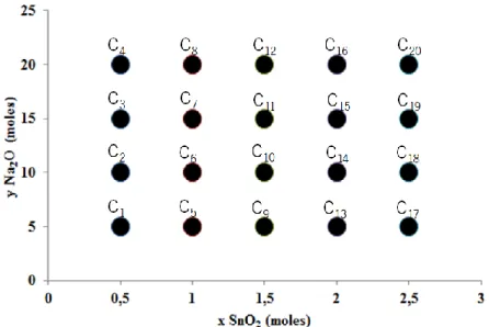
Figure 5. Composition field of the sodium-based stannosilicates (trial C), composition xNa2O-ySnO2-5SiO2∙500H2O. ... 10
Figure 6. Compositions of trial E. Samples E1 to E6 produced with 500 moles of H2O. ... 10
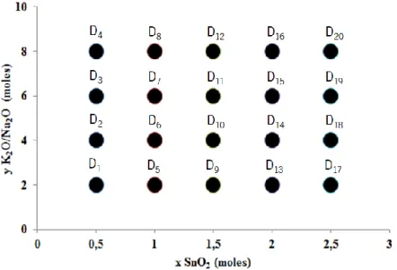
Figure 7. Composition field of potassium- and sodium- based tin silicates. Trial D with a composition of 10(xNa2O-yK2O)-5SiO2-zSnO2∙500H2O. . 12
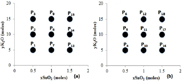
Figure 8. Composition field of trial P. (a) 2.5 moles of SiO2 (b) 5 moles of SiO2. All compositions were performed with 500 moles of H2O. ... 13
Figure 9. Autoclave used for stannosilicate hydrothermal synthesis; (a) autoclave components (photo) (b) assembly. ... 15
Figure 10. Unit cell representation [35] ... 23
Figure 11. Schematic of X-rays interactions with atomic arrangements. ... 24
Figure 12. Variation of a primary beam profile caused by multiple scattering. (a) Unaffected diffraction peak. (b) Moderate multiple diffraction. (c) Strong multiple diffraction [37]. ... 25
Figure 13. X-ray diffractometer (Bruker D8 Discover) [38]. ... 26
Figure 14. Schematics of SEM set-up. ... 27
Figure 15. Interaction of electrons and production of X-rays; (a) area of analysis (b) sample. ... 28
Figure 16. Photos of EDS and SEM equipment, FEI Nova (FEG/SEM); EDAX - Pegasus X4M (EDS/EBSD) [38] ... 28
Figure 17. Schematics of the zone of heterogeneous nucleation. ... 38
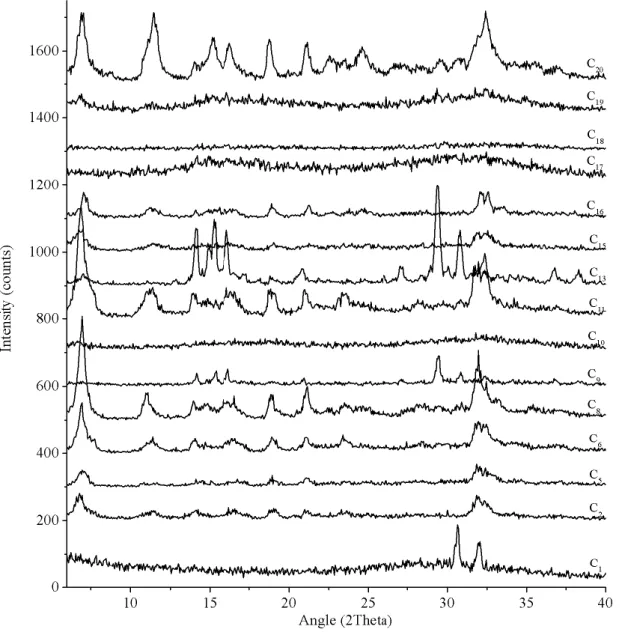
Figure 18. Experimental XRD powder patterns from all the synthesized sodium-based tin silicates (Trial C). Range from 6º to 40º 2theta. ... 40
Figure 19. Le Bail refinement of trial C13, experimental and simulated curves. Impurities as asterisk. ... 41
Figure 20. Attempt for Le Bail fit of C20 using Pmc21 space-group. Experimental calculated and difference curves well described but with high number of extra diffraction planes. ... 42
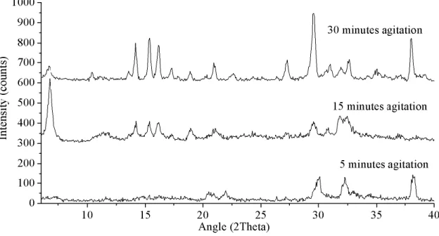
Figure 21. Experimental XRD powder patterns of trial TC2 to TC4. Synthesis at 200ºC for 2 days. agitations from 5 to 30 minutes.(5 minutes: unindexed phase, 15 minutes: unknown sodium phase (UM-1) and 30 minutes: AV-10) ... 43
Figure 22. Experimental powder XRD patterns of trials TC5 to TC8- 7 days synthesis and precursor agitation going from 5 to 30 minutes (5 minutes: unindexed phase, 15 minutes: unindexed phase and 30 minutes: analyzed bellow). ... 44
Figure 23. EVA search match for TC8, confirmation of soluble crystalline materials (red: Na2SiO3 blue: Na2(Sn(OH)6)). ... 44
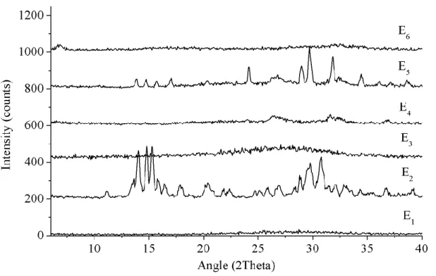
Figure 24. Experimental XRD powder patterns of trial E, 2 days synthesis and 15 minutes of agitation. ... 45
Figure 25. Experimental XRD powder patterns of trial D, 2 days synthesis and 15 minutes of precursor agitation. ... 47
Figure 26. Experimental and simulated curves of trials D1 (a) and D7 (b) extracted by Le Bail refinement. ... 48
Figure 27. SEM images of AV-7 (a) and AV-6 (b). AV-6 sample with some copper chloride contaminations (confirmed by EDS)... 49
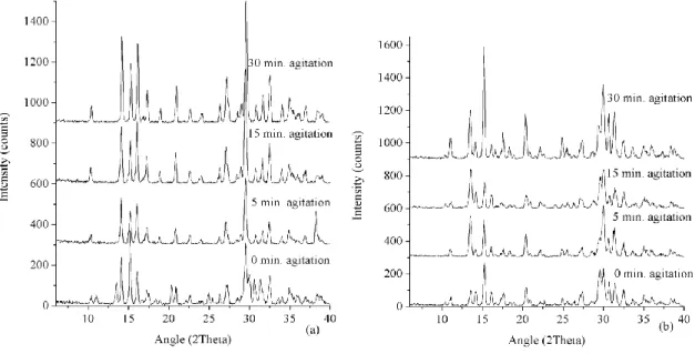
Figure 28. Experimental powder patterns from trials: TD1-TD4 for 2 days of synthesis (a); trials TD5-TD8 with 4 days synthesis (b). ... 49
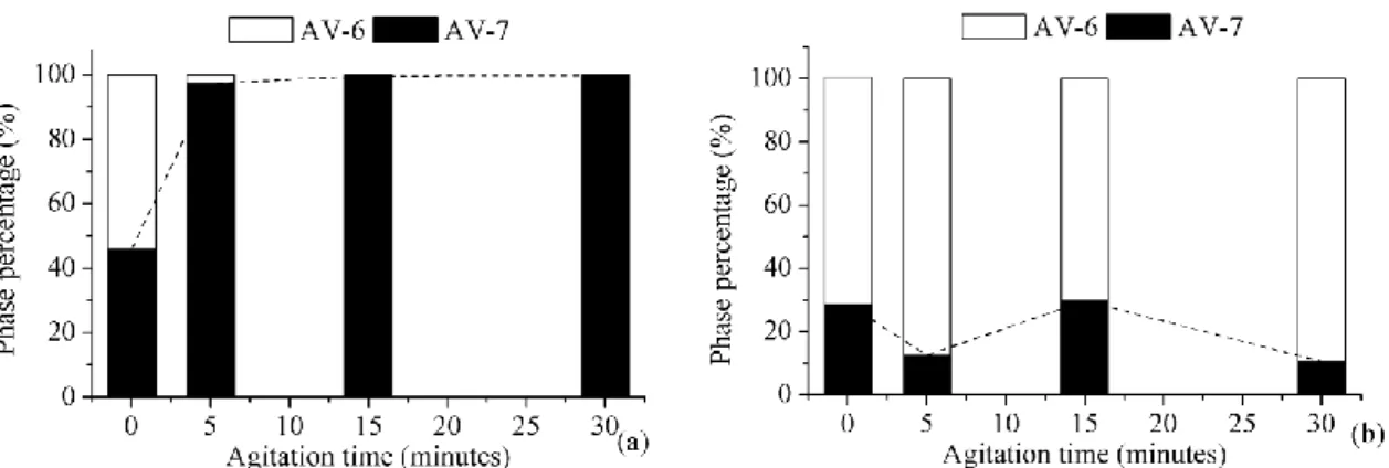
Figure 29. Phase percentage evolution: trial TD1 to TD4 (a); trial TD5 to TD8 (b). Data calculated by Rietveld refinement. ... 50
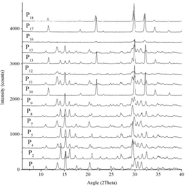
Figure 30. Experimental powder XRD patterns of trial P, 2 days synthesis and 15 minutes of precursor agitation. ... 52
Figure 31. Experimental and simulated XRD patterns produced by Le Bail method of TOPAS 3.0. ... 53
Figure 32. EDS spectrum of trial P10. ... 54
Figure 33. Representation of the developed structure for trial P10 (UM-2). Visualization in direction a (a) and direction b (b). ... 55
Figure 34. Experimental and simulated curve produced from Rietveld refinement procedure to trial P10. ... 56
Figure 35. SEM images of the tin silicate layered phase (UM-2) (a) and (b) are different zones from the material and (c) a detailed image of the cylinders like particles... 57
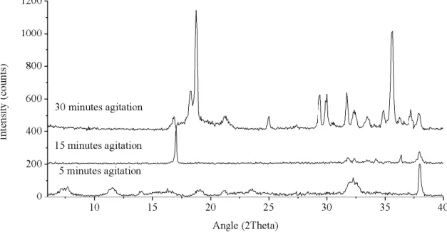
Figure 36. Experimental XRD powder patterns from trial TP, 2 days of synthesis (a) and 4 days of synthesis (b). ... 58
Figure 37. Phase percentage evolution for trial TP1 to TP4 (a) and trial TP5 to TP8 (b) (Values calculated by Rietveld refinement). ... 59
Figure 38. SEM image of Trial TP3. ... 60
Figure 39. Experimental powder XRD pattern of trial TL. Synthesized with P10 composition at various conditions. ... 61
Figure 40. Crystallization field of the sodium-based stannosilicates. Produced for 2 days of synthesis and 15 minutes of precursor agitation, based on trial C. ... 62
xii Dissertation in Materials Engineering
Figure 41. Crystallization field of the mixed sodium- and potassium- based stannosilicates. Performed for 2 days of synthesis and 15 minutes of
precursor agitation, based on trial D. ... 64
Figure 42. Crystallization field for the potassium- based stannosilicates. The synthesis was performed for 2 days and 15 minutes of precursor agitation, based on trial P... 65
Figure 43. Experimental powder XRD patterns from the ion exchanges of AV-6. Performed at 80ºC during 48 hours. ... 67
Figure 44. Experimental and simulated powder XRD patterns form the Le Bail refinement on the ion exchanged Sn-umbite. Exchange with copper for 24, 48 and 72 hours. ... 69
Figure 45. Experimental and simulated curves from the exchange with zinc. Simulation done using TOPAS 3.0. ... 70
Figure 46. Experimental powder XRD patterns of the AV-6 ion exchanges with Pb2+ and Al3+. performed for 18 hours at 50ºC. ... 71
Figure 47. Experimental and simulated curves from the TOPAS 3.0 Rietveld refinement. AV-6 ion exchange with aluminum for 18 hours at 50ºC. ... 72
Figure 48. SEM image of Av-6 produced by a clear precursor. Attempt of ion exchange with aluminum. ... 73
Figure 49 Experimental powder patterns of the ion exchanges of AV-7. Performed at 80ºC during 48 hours. ... 74
Figure 50. Experimental and simulated powder patterns from Le bail refinement on AV-7 ion exchanged with chromium. Exchanges during 24, 48 and 72 hours at 80ºC. ... 75
Figure 51. SEM image of AV-7 ion exchanged with Chromium. AV-7 produced on trial D12. ... 76
Figure 52 Experimental and simulated powder patterns of AV-7 Chromium exchange obtained by Rietveld refinement. ... 77
Figure 53. Simulated structures from AV-7 and Cr-AV-7. Direction a-axis of AV-7. (a) Direction c-axis of AV-7 (b). Direction a-axis of AV-7 Cr form (c). Direction c-axis of AV-7 Cr form (d). ... 78
Figure 54. Experimental and simulated curves of AV-7 ion exchange with copper. ... 79
Figure 55. SEM image of AV-7 ion exchanged with copper. Exchange during 48 hours at 80ºC. ... 81
Figure 56. Experimental and calculated curves from the Le Bail refinement of AV-7 ion exchanged with zinc. ... 82
Figure 57. SEM image of AV-7 ion exchanged with zinc for 24 hours at 80ºC... 83
Figure 58. Experimental powder XRD patterns of AV-7 ion exchanged with lead and aluminum. ... 84
Figure 59. Experimental and simulated curves of the Le Bail refinement of AV-7 ion exchanged with Pb and Al. ... 85
Figure 60. AV-7 simulated structure with plane (020). ... 85
Figure 61. Peak intensity difference between planes (002) and (020) in several AV-7 forms. ... 86
Figure 62. Experimental powder XRD patterns of the zirconium isomorphous substitutions on stannosilicates, performed at 200ºC for 2 days. .. 89
Figure 63. Titanium-tin precursors, 60% titanium 40% tin compositions. ... 90
Figure 64. Experimental powder XRD patterns of the titanium isomorphous substitutions performed at 200ºC for 2 days. ... 91
Figure 65. Experimental powder XRD patterns from trial ISS. Synthesis at 200ºC for 5 days. ... 92
Figure 66. Experimental and simulated powder XRD patterns of the isomorphous substitutions for 5 days and 30 minutes precursor agitation... 94
Figure 67. Experimental powder XRD patterns from isomorphous substitutions by germanium and bismuth. Sodium compositions synthesized for 2 days and potassium compositions for 2 days, all at 200ºC. ... 96
Figure 68. SEM image of potassium AV-7, isomorphous substation with germanium, AV-7 particles (blue) AV-6 particles (red) AV-7 nanorods (green). ... 97
Figure 69. Experimental powder XRD patterns of the samples exposed to 750ºC for 4 hours. ... 98
Figure 70. Experimental and simulated curves after Le Bail refinement of the cassiterite formed by thermal exposure of samples E6 and Cu-AV-6. ... 99
Figure 71. Experimental (Black) and calculated (red) PXRD patterns of AV-6 (a) and AV-6-Cu (b) performed at different temperatures. Unit cell axes (c) and lattice volume (d) of AV-6 and AV-6-Cu at different temperatures... 101
Figure 72. Experimental (black) and calculated (red) PXRD patterns of AV-6 (a) and AV-6-Cu (b) performed at ambient temperature after heating at different temperatures. Unit cell axes (c) and lattice volume (d) of AV-6 and AV-6-Cu at ambient condition. ... 102
Figure 73. Experimental powder XRD patterns of the thermally exposed samples. Exposure at 800ºC for 4 hours. ... 103
Figure 74. Experimental and simulated powder XRD patterns obtained by Le Bail refinement. Collected on sample F7, mixture of Sn-11 and AV-6. ... 104
Figure 75. Le Bail refinement of the high resolution powder XRD pattern of trial F4. Experimental (black) calculated (red). ... 105
Dissertation in Materials Engineering xiii
Figure 77. Solid block (Sample H7). ... 107
Figure 78. Experimental powder XRD patterns of the thermally exposed samples. Exposure at 1000ºC for 5 hours. ... 108
Figure 79. Experimental, calculated and plane occupation patterns of the Le Bail refinement for trial H3. ... 109
Figure 80. Experimental and simulated plots of the Sn-AV-11 heated at 1000ºC for 5 hours. ... 110
Dissertation in Materials Engineering xv
Table Index
Table 1. Experimental parameters of trial TC. Precursor agitation time in minutes and synthesis duration in days. ... 11Table 2 Experimental parameters of trial TD. Precursor agitation time in minutes and synthesis duration in days. ... 12
Table 3. Experimental parameters of trial TP. Precursor agitation time in minutes and synthesis duration in days. ... 14
Table 4. Experimental parameters of trial TL. Precursor agitation time in minutes and synthesis duration in days... 14
Table 5. Ion exchanges performed on AV-6 and AV-7. Time, temperature solution concentration and type of source. * Sigma ALDRICH ** FLUKA. ... 17
Table 6. Compositions and preparation parameters for the isomorphous substitutions by Zr and Ti. ... 19
Table 7. Composition and synthesis parameters for the isomorphous substitution by Zr and Ti at extended synthesis times. ... 20
Table 8. Compositions and synthesis parameters of the isomorphous substitutions by Ge and Bi. ... 20
Table 9. Information on the stannosilicates exposed to 750ºC for 4 hours. ... 21
Table 10. Information on the materials exposed to 800ºC for 4 hours. ... 22
Table 11. Information on the materials exposed to 1000ºC for 5 hours. ... 23
Table 12. Synthesis results for the sodium-based tin silicates for 2 days synthesis and 15 min. of precursor agitation (Trial C). ... 33
Table 13. Synthesis results for trial TC, each composition agitated for 0, 5, 15 and 30 minutes. ... 34
Table 14. Synthesis results from trial E. 2 days synthesis and 15 minutes of precursor agitation. ... 35
Table 15. Synthesis results for the sodium and potassium based stannosilicates (Trial D). Two days of synthesis and 15 minutes of precursor agitation. ... 35
Table 16. Synthesis results for Trial TD. Composition from 1-4 and 5-8 are equal (see in appendix 1). Precursor agitation time for 0, 5, 15 and 30 minutes. ... 36
Table 17. Synthesis results for potassium based stannosilicates (Trial P). Syntheses for 2 days at 200ºC and precursor agitation of 15 minutes. 37 Table 18. Synthesis results for trial TP, trials 1-4 composition equal to P1 trials 5-8 composition equal to P10. Precursor agitation times for 0, 5, 15 and 30 minutes. ... 37
Table 19. Synthesis results of Trial TL. All trials performed at the same composition (trial P10). ... 38
Table 20. Crystallographic data of trial C13, performed by Le Bail using hkl data from AV-10. ... 41
Table 21. Refinement results of trial D1 and D7. Obtained by Le Bail with hkl data from AV-7 and AV-6. ... 48
Table 22. Crystallographic data from the Le Bail refinement performed to trial P10. ... 53
Table 23. Chemical composition of trial P10, obtained by EDS. ... 54
Table 24. Chemical composition of trial TP3 obtained by EDS. ... 59
Table 25. Crystallographic data from AV-6 ion exchanges with copper. Exchanged for 24, 48 and 72 hours. ... 68
Table 26. Crystallographic data from Rietveld refinement of the exchanged form of AV-6, exchange with zinc at 80ºC during 48 hours. ... 70
Table 27. Crystallographic data from the Rietveld refinement. AV-6 ion exchange with aluminum. ... 71
Table 28. EDS results of AV-6 exchanged with aluminum... 72
Table 29. Crystallographic data of the AV-7 ion exchanges with chromium. Exchanges performed during 24, 48 and 72 hours at 80ºC. ... 75
Table 30. Chemical composition of AV-7 ion exchange with chromium. ... 76
Table 31 Crystallographic data from the Rietveld refinement to the AV-7 chromium exchanged material. Exchange at 80ºC during 72 hours. ... 77
Table 32. Atomic coordinates for AV-7 Cr-form. ... 78
Table 33. Crystallographic data for AV-7-ion exchange with copper. Refinement by Le Bail method. ... 79
Table 34. Chemical composition of the AV-7 ion exchange with copper for 48 hours. ... 80
Table 35. Crystallographic data from the Le Bail refinement to the AV-7 ion exchanges with zinc. ... 81
Table 36. Chemical composition of AV-7 ion exchanged with zinc for 24 hours. ... 82
Table 37. Crystallographic data from Le Bail refinement of AV-7 ion exchanged with Pb and Al. ... 84
Table 38. Synthesis results from the isomorphous substitutions with 20% (IS1 to IS4) and 40% (IS5 to IS6) of zirconium. ... 88
Table 39. Type of precursor and synthesis result of all isomorphous substitutions with titanium. Performed at 200ºC for 2 days. ... 90
Table 40. Crystallographic data from the isomorphous substitutions performed for 5 days synthesis at 30 minutes of precursor agitation time. Substitutions by zirconium and titanium. ... 93
Table 41. Precursor type and synthesis result from the isomorphous substitutions by germanium and bismuth. ... 95
xvi Dissertation in Materials Engineering
Table 43. Crystallographic data of thermally exposed samples E6 and Cu-AV-6. Exposure for 4 hours at 750ºC. ... 99
Table 44. Crystallographic data from sample F7. Le bail refinement using AV-6 and Sn-AV-11 data. ... 104
Table 45. Crystallographic data of Le Bail refinement of sample F4. ... 105
Table 46. Crystallographic data for Zn-AV-7 after 800ºC for 4 hours. ... 106
Table 47. Crystallographic data from the Le Bail refinement of trial H3. Obtained using a high resolution powder XRD pattern. ... 109
Table 48. Crystallographic data from the materials transformed into Sn-AV-11. ... 110
Dissertation in Materials Engineering 1
V Introduction
5.1 Microporous Silicates
The history of the microporous materials starts with the discovery of the zeolite minerals. This species were discovered in 1756 by Swedish mineralogist Axel Cronstedt, who gave their common name after upon rapidly heating the material release a steam from absorbed water. Thus, he called the materials zeolites, from the Greek (zéo), meaning “to boil” and (lithos), meaning “stone” [1].
Science advanced and now they are known as hydrated aluminosilicates containing pores of molecular size. The structures of these materials are composed of interconnected SiO4 and AlO4 that form a microporous framework. These types of frameworks form negative charged zones in the pores which are compensated by positively charged cations. Along with those cations, the pores also contain structural water molecules. In nature there are large deposits of zeolites but the synthetic ones are more important due to their vast industrial applications. Zeolite A was one of the first widely used commercial zeolites. The success of this material was the trigger point to start the study of new forms and to incorporate these materials in the market [2]. Zeolites are now of vital importance in the fuel industry performing as catalyst to produce gasoline [3] and as molecular sieves used for gas and liquids separations [4]. To date, there are more than 200 framework types of zeolites and the number of hypothetical is still pending a discovery [5].
Recently, the family of the zeolites has been expanded to other silicate molecular sieves obtained by the substitution of AlO4 tetrahedra by various metals in octahedral coordination. This resulted in new materials (chemically and structurally) with classical zeolitic and new applications in areas such as optoelectronics, nonlinear optics, batteries, magnetic materials and sensors [6].
Within the family of the tetrahedral-octahedral molecular sieves, some of the most important members are the transition metal as titanosilicates, vanadosilicates and zirconosilicates [6]. In the common case, microporous silicates are produced in Teflon-line autoclaves under mild hydrothermal conditions at temperatures from 150 to 230ºC during 1 to 10 days [6].
Across the last years many attempts have been made to synthesize new microporous silicates and zeolites with different structures and new potential applications. There is also a
2 Dissertation in Materials Engineering
great effort to modify the existing microporous structures in order to infuse them with new properties and improve the known ones. This work focuses on a recent and perspective class of materials as the microporous tin silicates. These solids offer a number of less explored structures and properties that can be an alternative to ones of the zeolites and other tetrahedral-octahedral molecular sieves.
5.2 Previous studies
In number of microporous materials it is common to see the same structures in different chemical forms. These materials are often structural analogues of existing minerals in the nature. Among them one of the most studied is the analogue of the zirconosilicate mineral, umbite, whose tin [6], titanium [7-9] and zirconium [10-12] forms have been prepared in laboratory conditions. Its porous structure is formed by an interconnection of corner sharing SiO4 tetrahedra and MO6 octahedra of various elements. In the space of the pores resides a water molecule and K+ ions that compensate the negative charge of the framework. A model of this molecular sieve can be seen in figure 1. The structure has orthorhombic crystal system with P212121 space-group and the unit cell dimensions depending on its chemical composition of the octahedral site. These isostructural phases are often called after the institutions where they have been synthesized for the first time. For example the
titanium form is called AM-2 (Aveiro Manchester – 2) and the tin form AV-6 (Aveiro – 6).
The applied properties of different chemical forms of the synthetic umbite have been widely studied. Ion exchange experiments of titanium form showed possibility to uptake Na+, Cs+, Mn2+, Sr2+, Ca2+ and Rb2+. In these studies the
change of the charge
compensation cations of AM-2 revealed structural changes and reduction of thermal stability [13-14, 15]. Some ion exchanged forms demonstrated a potential for advanced applications. For example, zirconium umbite exchanged with Zn2+ resulted in an antibacterial microporous material [16]. A similar property was discovered on Zn-AM-2 and Zn-ETS-4 (Engelhard titanium
Figure 1. Crystal structure of AV-6, image along a-axis obtained by software Diamond 3.0
Dissertation in Materials Engineering 3
silicate-4). These molecular sieves prove to be effective in the selective elimination of cancer cells [17].
Apart from the ion exchange properties, umbite type structure in its titanium (AM-2) and tin (AV-6) forms shows excellent potential for preparation of membrane for separation of H2 and N2. AM-2 shows higher potential and higher thermal stability than AV-6 but the tin microporous framework shows promising potential for the use in CO2 separation [18]. In terms of structure manipulation, the change of the octahedral site allows finely adjustable lattice dimensions and pore sizes. In this respect, there are reports on synthesis of Ti-V [19], Ti-Zr [20], and Sn-Zr [20] forms of umbite.
Another important microporous ion exchanger tin silicate is EMS-2. Along with AV-6, these materials are the only forms of tin molecular sieves to be studied in terms of ion exchange. Experiments with Mg2+, Ca2+, Sr2+ and Ba2+ resulted in partly or fully ion exchanged forms. The thermal studies of these ion exchanged forms revealed that all modified frameworks lose stability due to the external ion capture [21].
Thermal properties investigation revealed how structurally different materials AV-6 and AV-7 are transformed into Sn-AV-11 [22]. AV-7(Aveiro – 7) is a microporous tin silicate which is structural analogue of the mineral kostylevite [23]. In spite of different symmetry, AV-7 (monoclinic) and AV-6 (orthorhombic) have the same structural motif. The pore system of both phases is composed of 6-ring and 8-ring channels. With equal occupation on the 6-ring pore, AV-6 and AV-7 differ in the occupation of the 8-ring channel. AV-7 has sodium and potassium ions as charge stabilizers. Despite the resemblances between these two frameworks the ion exchange properties are very different. While AV-6 is easily exchanged to various cation forms, for AV-7 no ion exchange forms have been ever reported.
To date there are no more than 10 known microporous tin silicate structures, AV-6[6], AV-7 [23] and EMS-2 [24] produced by conventional hydrothermal synthesis. Sn-AV-14 [25] and AV-10 [26], two sodium based stannosilicates produced by a two stage synthesis were the synthesis can take more than 10 days. Sn-AV-11 [22] and Sn-wadeite [22] produced by high temperature transformation. All these synthesis of stannosilicates are performed from gels with tin chloride (IV) and sodium metasilicate. As a result they are always synthesized from white gels containing sodium ions. Similar to these frameworks there are chemically different forms of stannosilicates produced by high temperature and high pressure synthesis [27].
4 Dissertation in Materials Engineering
A recent study reported the first hydrothermal synthesis of tin silicates using a clear solution as precursor [28]. The new synthesis approach was based on substitution of the tin chloride (IV) by tin chloride (II) in the initial precursor. This work also reported the first ion exchanges with Cu2+. The copper ions in the pores of Cu-AV-6 resulted in decreasing the initial orthorhombic symmetry to monoclinic one. Direct comparison between the powder XRD patterns shows a pronounced peak shift and appearance of new diffraction planes (figure 2) [28].
Figure 2. X-Ray diffraction powder patterns of AV-6 and Cu-AV-6.
Cu-AV-6 contains copper ions captured in the 8-ring channels. The occupation is shared with disordered water molecules. The 6-ring pores remain majorly occupied by potassium, as the Rietveld refinement model
shows in figure 3 [28]. The same study showed that zinc can also be captured by this framework. In this case the decrease to the monoclinic space-group was complete and the Zn-AV-6 sample turned into a mixed phase material. The exchange with lead on the same material resulted in the framework
destruction. The reversed potassium ion exchange to the Zn-AV-6 and Cu-AV-6 showed that these frameworks can return to the original state (orthorhombic). When the copper and zinc ion
Figure 3. Crystalline structure of Cu-AV-6, cif obtained by Rietveld refinement and image by Diamond 3.0.
Dissertation in Materials Engineering 5
exchanged forms of AV-6 are exposed to high concentrated (1Mole) solutions of potassium (KCl) the AV-6 original chemical composition is restored [28].
5.3 Motivation and Objectives
The motivation for this work is driven by the potentially novel and improvement of the known applications of the microporous tin silicates. This motivation is based on the gained experience during the previous work with stannosilicates [28]. The obtained results showed that the stannosilicate system is promising not only for the preparation of new materials but also for the discovery of new ion exchange properties of known molecular sieves. The work performed so far showed the great potential of the synthesis using a transparent precursor. It also showed that there are many possible elements that can be captured in the tin silicate porous framework types. As a result, the obtained materials revealed different properties than the initially synthesized phase. In this respect, the current work is a natural continuation of the previous experience and the objectives include:
a) Development of a new method for the synthesis of tin silicates from a clear solution; b) Systematic study of the influence of the initial physicochemical conditions on the run
product;
c) Optimization of the synthesis conditions;
d) Synthesis and characterization of new stannosilicates;
e) Probing isomorphous substitutions and ion exchange properties with various elements; f) Study the thermal properties of the obtained materials.
The purpose of this thesis is to extend a previous work in the field of tin silicates. This work intends to establish the optimal physicochemical conditions for synthesis of stannosilicates and to create fields of crystallization where the intended structures can be easily fabricated.
The new synthesis method by clear precursor has unknown outcome in terms of microporous tin silicates formation. In order to understand the full potential of this method this work focus on the behavior of the sodium and potassium as framework stabilizers, their role in the solution and the limitation and advantages of each element in this new method. This work searches for chemical compositions that allow the formation of cheaper materials by the reduction of synthesis time and temperature. The final point of interest in the synthesis procedure is the study of the early physicochemical compositions of the solution and its role in the final product. Precursor pH has been already proven as an important factor on silicate production [29]. However there are many other unstudied factors that can induce structure
6 Dissertation in Materials Engineering
formation. This work studies the effects of solution temperature and agitation level and its importance in the production of stannosilicates.
New ion exchanges in tin silicates frameworks were also attempted. As seen before [19] the capture of an external ion can transfer the properties of that element to the silicates material. With that in mind it is possible to think in the doping of stannosilicates to improve its normal capacities. This work attempts the incorporation of antibacterial, magnetic and optical properties by the exchange of the normal alkaline elements present in stannosilicates for Zn2+, Cu2+ and Cr3+, respectively. Since the storing of the captured element is very good, a common ion exchange tested is the ability to capture potential radioactive elements. Like in most silicates this work studies the capacity of stannosilicates to capture hazardous but interesting elements like Cs+ and Sr2+. These two exchanges serve as direct comparison between these molecular sieves and all other silicates, and a positive result could indicate the eminent application of stannosilicates in nuclear waste disposal.
In this respect there is another great application for these microporous materials, due to the ability of capturing loose ions in a solution this material can work in water purification. The capture of elements like Pb2+, Fe2+, Al3+ and some of the previously referred (like Cu2+) can be used for water treatment or recycling of polluted liquids. The use of microporous materials in the recycling and energy harnessing of used fried oil is a common procedure [29], the search for these properties on stannosilicates can result in a new application for this recent material. to understand if the tin silicate frameworks can capture these and other ions this work searches for changes in the materials atomic distribution. These changes must be visible both at a structural level (detected by XRD) and at a chemical composition level (detected by EDS).
To improve and modify the properties of tin silicates isomorphous substitutions were also attempted. These incorporations of new octahedral elements can alter the pores sizes or drastically change the structure shape and properties. The goal was to find and analyze new mixed metal stannosilicates using Zr, Ti, Ge and Bi as substitution elements. Zirconium silicates have great thermal stability however the synthesis of theses microporous materials require higher temperatures or longer time comparing to tin silicates. The incorporation of Zr to tin silicate compositions can result in mixed stannosilicates with higher thermal stability and harder grains. It can also result in zirconosilicates with lower synthesis temperatures and with new transparent precursor synthesis method. Titanium has similar size to tin. When 6 coordinated titanium ion has radii of 0.605 Å [30] and tin one is 0.69 Å [31]. The size difference between the ions is
Dissertation in Materials Engineering 7
enough to provoke slightly change in the pore size when one of the ions is substituted by the other. The microporous framework of the mineral umbite can be produced with both ions as octahedral element. The incorporation of both ions in a umbite composition can easily form a mixed octahedral Ti-Sn-umbite material.
The isomorphous substitutions by germanium presents great promise since this element has the ability to form tetrahedra, octahedra and pentahedra; therefore it can substitute both tin and silicon in the framework, creating mixed stannosilicates, mixed germanosilicates or tin germinates. The incorporation of this element can perform several changes and severally distort the stannosilicate structures. The only downsize to its use is the cost of the source; germanium is a very expensive element so only a few tests were performed. The isomorphous substitution by bismuth is interesting due to its valence of 3+ which differ that of Sn and Si. Successful incorporation of bismuth can seriously affect the whole spectrum of properties. The problem of bismuth is its fast precipitation of its source (BiCl3) in aqueous solutions which requires experiments with different sources.
Finally, thermal study of all the synthesized and modified structures was performed. These tests served to reveal the thermal stability and possible thermal transformations of the obtained phases.
All synthesized and structurally modified phases were characterized by powder X-ray diffraction (XRD).
Dissertation in Materials Engineering 9
VI Experimental
6.1 Synthesis
In order to evaluate the potential of this synthesis method the precursor preparation must be fully understood and all possible variables must be eliminated. To understand the effects of composition all syntheses were performed by the same preparation steps. The silica dissolution was performed at 90ºC at 240 rpm of magnetic agitation. Silica was dissolved in the alkaline water solution which was always formed from an element in the hydroxide form. The solid alkaline was dissolved in distilled water by the same conditions 90ºC and 240 rpm. Separately the tin chloride solution was prepared dissolving the SnCl2∙2H2O in 50% of all the compositional water. The total water in the stannosilicates precursors was fixed at 500 moles and due to maximum capacity of the autoclave all compositions were calculated for 40 grams of water. The mixing of the tin chloride solution and alkaline solutions was performed at 154ºC at agitation speed of 240 rpm. The final precursor was then agitated for 15 minutes.
All these steps can be seen in figure 4, schematically showing the solution making process. The precursor was then locked in a Teflon lined stainless steel autoclave and placed in oven for 2 days at 200ºC for hydrothermal synthesis. The resulting products came in the form of powder and were washed and dried at room temperature.
Figure 4. Precursor preparation method, stages 1 to 7 performed at 90ºC with 240 rpm agitation and stage 8 performed at 145ºC with 240 rpm during 15 minutes.
The sodium based tin silicates were prepared from transparent solutions with varying compositions. The general formula of these compositions was yNa2O-xSnO2-5SiO2∙500H2O,
10 Dissertation in Materials Engineering
where silica and water were invariable terms and tin oxide and sodium followed the values shown of figure 5. These 20 compositions were referred as trial C. To produce these precursors the general method, figure 4, was adapted to only one hydroxide that was mixed with 50% of all water. Despite the adjustment all samples were produced at the standard precursor and synthesis parameters.
Figure 5. Composition field of the sodium-based stannosilicates (trial C), composition xNa2O-ySnO2-5SiO2∙500H2O.
To study the effects of more balanced solutions, with closer ratios, more sodium based compositions were performed. These 6 compositions (trial E), seen in figure 6, were low concentration alkaline precursors and some of them had a ratio of tin/silicon different from the ones performed on trial C. This test completes the previous composition field and studies the influence of the alkaline material on stannosilicates formation. All compositions included the same synthesis procedure. The precursor preparation steps of figure 4 and a synthesis at 200ºC for 2 days, equal to trial C.
Dissertation in Materials Engineering 11 For the last synthesis with sodium based tin silicates the precursor agitation and synthesis time were changed. The used composition was 15Na2O-5SiO2-1.5SnO2∙500H2O (trial C11). The precursor agitation times were 0, 5, 15 and 30 minutes and these different agitation precursors were all heated for 2 and 7 days. The individual parameters of this test, trial TC, can be seen in table 1. The 0 minutes precursor agitation time represents a manual agitation at room temperature until total dissolution and dispersion. All other variables, temperature, amount of liquid, recipient, magnetic agitator and position on the magnetic plate were kept constant. This ensured a single parameter study.
Table 1. Experimental parameters of trial TC. Precursor agitation time in minutes and synthesis duration in days. Trial Agitation Time (min.) Time of Synthesis (days)
0 2 5 2 15 2 30 2 0 7 5 7 15 7 30 7
In succession to these compositions the sodium and potassium based stannosilicates were studied. The general synthesis used composition was 10(xNa2O-yK2O)-5SiO2-zSnO2∙500H2O called trial D. This trial focused on the effects of both sodium and potassium as negative charged compensators on microporous tin silicates.
To perform these compositions the standard precursor preparation parameters of figure 4 were used. In this formula the silicon and water values remained constant and tin, sodium and potassium followed the values given by figure 7. Tin content changed from 0.5 to 2.5 moles (as in trial C) and the ratio between potassium and sodium from 2 to 8 with a total weight of 10 moles in all trials. The trial D was composed of 20 different compositions where sodium and potassium were always present. After precursor preparation the solutions were placed in autoclaves and heated at 200ºC during 2 days.
12 Dissertation in Materials Engineering
Figure 7. Composition field of potassium- and sodium- based tin silicates. Trial D with a composition of 10(xNa2O-yK2O)-5SiO2
-zSnO2∙500H2O.
To complete the study on potassium and sodium based stannosilicates the precursor and synthesis parameters were changed. This allowed studying its influence in the resulting materials and structures. The chosen compositions were trial D1 (3.33Na2O-6.66K2O-5SiO2 -0.5SnO2∙500H2O) and D7 (1.43Na2O-8.57K2O-5SiO2-0.5SnO2∙500H2O). The variable parameters changed were final the precursor final agitation time and the synthesis duration.
The two compositions were prepared at precursor agitation times of 0, 5, 15 and 30 minutes resulting in 8 different solutions which were heated for a certain time. The D1 composition solutions were synthesized for 2 days and the D7 composition solutions for 7 days. This test was called trial TD and all its individual parameters can be seen in table 2.
Table 2 Experimental parameters of trial TD. Precursor agitation time in minutes and synthesis duration in days. Trial Composition (trial ) Agitation Time (min.) Time of Synthesis (days)
0 2 5 2 15 2 30 2 0 7 5 7 15 7 30 7
The next syntheses included potassium based stannosilicates. The explored compositions had the general formula of yK2O-2.5SiO2-xSnO2∙500H2O and yK2O-5SiO2
-Dissertation in Materials Engineering 13 xSnO2∙500H2O. Silicon and water were fixed in each composition and the values of potassium and tin followed the numbers given by figure 8. Potassium had a minimum value of 5 and a maximum of 15 and tin a minimum of 0.5 and a maximum of 1.5 moles. This resulted in 18 different compositions, designated as trial P. It was used the standard synthesis procedure shown in figure 4. Since there was only one hydroxide source, the potassium hydroxide was dissolved in 50% of all compositional water.
All 18 compositions were synthetized at 200ºC for 2 days. This test included a change in silicon quantity to test further ratios between the three elements.
Figure 8. Composition field of trial P. (a) 2.5 moles of SiO2 (b) 5 moles of SiO2. All compositions were performed with 500 moles
of H2O.
Synthesis with potassium based tin silicates with different precursor parameters were also carried out. The chosen compositions were 5K2O-5SiO2-0.5SnO2∙500H2O (trial P4) and 5K2O-5SiO2-1SnO2∙500H2O (trial P10). The changed parameters were once again the final precursor agitation and the synthesis time. Both compositions were performed with 0, 5, 15 and 30 minutes of precursor agitation time and synthesized for different times. P4 composition solutions were synthesized for 2 days and P10 composition solutions for 4 days. The synthesis of all 8 solutions, trial TP, was performed in autoclaves at 200ºC. The individual preparation and synthesis parameters can be seen in table 3.
14 Dissertation in Materials Engineering
Table 3. Experimental parameters of trial TP. Precursor agitation time in minutes and synthesis duration in days. Trial Composition (trial ) Agitation Time (min.) Time of Synthesis (days)
0 2 5 2 15 2 30 2 0 4 5 4 15 4 30 4
To explore the possibility for faster synthesis procedures variable time for agitation for P10 composition was tested (figure 8). These time controlled precursors with 10, 15, 20 and 30 minutes of agitation were produced and synthesized at different times, 1 and 2 days at 200ºC. The 5 different tests were called trial TL and its individual preparation parameters can be seen in table 4.
Table 4. Experimental parameters of trial TL. Precursor agitation time in minutes and synthesis duration in days. Trial Agitation Time (min.) Time of Synthesis (days)
10 1
15 1
20 1
15 2
30 2
All syntheses were performed using SnCl2∙2H2O (Sigma – ALDRICH Pu>98%) NaOH (Sigma – ALDRICH), KOH (Sigma – ALDRICH) and SiO2 (Cab-osil®M-5) has sources of the required elements. To calculate the weights of reagents needed to create each composition it was used the following equation:
Where the Qc was the quantity of the wanted element (in moles), Ts the total weight of the solution (established by the maximum capacity of the autoclave 40 grams), MR is the atomic weight of the source or reagent, MH2O is the atomic weight of water and QH2O is the quantity of water in the composition (in moles). By calculating this it is obtained PR that is the amount of
Dissertation in Materials Engineering 15 source needed to execute each composition. For future consult all calculated compositions can be seen in APENDIX 1.
As mentioned before, the autoclave is a Teflon lined stainless steel closed recipient used to accommodate liquid (in this case the stannosilicates solutions) and to prevent gas or liquid escape during the synthesis process.
In this work the volume of solution in autoclave was always controlled and filled near 70% of the total volume which assured auto-generated pressure that do not exceed the autoclave stability. This allowed obtaining the maximum yield of the run product for each precursor. The used autoclave and assembly method can be seen in figure 9.
16 Dissertation in Materials Engineering
6.2 Ion Exchange
The framework of microporous materials is the rigid part of crystal structure that accommodates water molecules and charge compensating cations. These positive charged ions have high mobility and can be replaced by similar ions if the size and coordination allow it [32]. Cation charge can also influence the success of exchange. According to recent studies, if two similar cations have different charge the higher charged cation has higher affinity to the microporous structure [33]. Like any other diffusion process, ion exchange also is improved by the increase of time and temperature. The increase in temperature allows the pores to expand and its occupant and outside cations to vibrate more intensely. This increases the penetration of the external ions and the possibilities of exchange. The time of exchange increases the amount of collisions between cations increasing therefore number of exchanges even in low success rate environments. Time and temperature increase have associated problems. Time of exposure in liquid solutions increases the effects of material dissolution due to aggressive pH. Temperature increase can cause thermal degradation. For all that it is indispensable to fully understand the porous structure and its initial occupancy to be able to manipulate and modify its pore contents by ion exchange.
Because of the required about its structures and the necessity of a continuous perfect production the only to stannosilicates ready for ion exchange were AV-6 and AV-7. These two frameworks have pores occupied by potassium, on AV-6, and by sodium and potassium, on AV-7, and the goal was to fully or partly exchange it for equal and different charge cations. For that the microporous material was placed in liquid solutions containing the exchange cations. These solutions had concentrations with the standard value of 1 Mole. However, due to the low solubility of some cations sources this value was sometimes changed. The amount of stannosilicate used in each exchange was fixed at 0.1 grams. The individual parameters of all the exchanges performed are listed in table 5, where the temperature, time, solution concentration and source of cation can be seen.
Dissertation in Materials Engineering 17 Table 5. Ion exchanges performed on AV-6 and AV-7. Time, temperature solution concentration and type of source. * Sigma
ALDRICH ** FLUKA. CuCl2* (1 M) ZnCl2** (1 M) CrN3O9∙9H2O* (1 M) Phase Time → 18 h 24 h 48 h 72 h 18 h 24 h 48 h 72 h 18 h 24 h 48 h 72 h AV-6 50ºC 80ºC X X X X X Av-7 50ºC 80ºC X X X X X X SrCl2* (1 M) PbCl2* (0.01 M) AlCl3** (1 M) Phase Time → 18 h 24 h 48 h 72 h 18 h 24 h 48 h 72 h 18 h 24 h 48 h 72 h AV-6 50ºC X X 80ºC X Av-7 50ºC X X 80ºC X X X CsCl* (0.5 M) FeCl3* (1 M) NaCl* (1 M) Phase Time → 72 h 24 h 48 h 72 h 18 h 24 h 48 h 72 h 18 h 24 h 48 h 72 h AV-6 50ºC 80ºC X X X Av-7 50ºC 80ºC X X X
For long ion exchange times (over 24 hours) evaporation may change the cations concentration. Therefore more solution was added in 24 hours periods to balance and control cation quantities. To improve the changes of exchange and to increase the materials ability to form suspensions, all stannosilicate samples were milled into a very fine powder. The ion exchanges were performed in glass bowls with adapted cover to reduce evaporation. The recipients were placed in a BINDER oven with digital temperature control with a maximum deviation of 1ºC. After exchange all products were washed, filtered and dried at room temperature.
The success of ion exchange was evaluated by XRD where the changes in the crystalline material were detected. The confirmation of the cation capture came from EDS.
18 Dissertation in Materials Engineering
6.3 Isomorphous substitution
The doping and partial substitution of structural elements is a common procedure in ceramic materials. This doping needs to be in very small amounts in order to preserve the structure of the original material. In silicates there is another process of doping that does not suffer from that problem. Silicates frameworks can fully substitute the octahedral or tetrahedral element without significant structural changes. This is proven by the amounts of mineral analogues produced in laboratory. The substitution is theoretically possible to all elements that possess the same oxide formations [34]. In stannosilicates the substitution can occur in the octahedral tin and in the tetrahedral silicon atom, each of the elements can be replaced by other metals with the same coordination and similar size. On the contrary to ion exchange the isomorphous substitution is realized during the process of crystallization. When an isomorphous substitution is tried the goal is to use a precursor composition of a determinate structure and infuse it with different elements. This changes the materials properties and pores dimensions without changing the crystal system or the framework type. However, each element has its own chemical and physical behavior and its introduction to the precursor, even in small amounts, can create new reactions that lead to new types of frameworks. The more similar the elements are, chemically, in size, coordination and valance the higher are chances of creating a single phase mixed material.
To perform the isomorphous substitution, this work used the precursor preparation parameters referred in figure 4 with a single modification. The incorporation of tin chloride was done in parallel with the incorporation of the substitution element. The compositions had a gradual increase in the amount of tin substitute. The synthesis parameters were equal to the ones used in the synthesis chapter, 200ºC for 2 days. This also served to compare the influence of a new element in the synthesis success and quality. Maintaining the synthesis parameters equal allowed a direct comparison and a better prediction of the resulting structures. The structures obtained during the synthesis trials were again synthesized with substitution elements. The compositions used here were the ones perfected in the synthesis trials. The isomorphous substitutions performed can be seen in table 6 where it is shown the element of substitution, its percentage in relation with tin, the modified composition, its original trial and the precursor preparation and synthesis parameters. The first substitutions were performed with zirconium and titanium. The percentage substituted was 20% and 40% of Zr and 20%, 40% and 60% of Ti. The 60% isomorphous substitutions dictated that more titanium than tin was available for framework construction.
Dissertation in Materials Engineering 19 Table 6. Compositions and preparation parameters for the isomorphous substitutions by Zr and Ti.
Trial Element Percentage changed (%) Original Trial Composition Time and temperature of agitation (min.-o C) Time and temperature of synthesis (days.-o C) IS1 Zr 20
D1 6.6K2O-3.3Na2O-5SiO2-0.1ZrO2-0.4SnO2∙500H2O 15min-145ºC 2- 200ºC
IS2 P1 5K2O-2.5SiO2-0.1ZrO2-0.4SnO2∙500H2O 15min-145ºC 2- 200ºC
IS3 C9 10Na2O-5SiO2-0.3ZrO2-1.2SnO2-500H2O 15min-145ºC 2- 200ºC
IS4 C20 20Na2O-5SiO2-0.5ZrO2-2SnO2-500H2O 15min-145ºC 2- 200ºC
IS5
40
D1 6.6K2O-3.3Na2O-5SiO2-0.2ZrO2-0.3SnO2∙500H2O 15min-145ºC 2- 200ºC
IS6 P1 5K2O-2.5SiO2-0.2ZrO2-0.3SnO2∙500H2O 15min-145ºC 2- 200ºC
IS7 C9 10Na2O-5SiO2-0.6ZrO2-0.9SnO2-500H2O 15min-145ºC 2- 200ºC
IS8 C20 20Na2O-5SiO2-1ZrO2-1.5SnO2-500H2O 15min-145ºC 2- 200ºC
IS9
Ti
20
D1 6.6K2O-3.3Na2O-5SiO2-0.1TiO2-0.4SnO2∙500H2O 15min-145ºC 2- 200ºC
IS10 P1 5K2O-2.5SiO2-0.1TiO2-0.4SnO2∙500H2O 15min-145ºC 2- 200ºC
IS11 C9 10Na2O-5SiO2-0.3TiO2-1.2SnO2-500H2O 15min-145ºC 2- 200ºC
IS12 C20 20Na2O-5SiO2-0.5TiO2-2SnO2-500H2O 15min-145ºC 2- 200ºC
IS13
40
D1 6.6K2O-3.3Na2O-5SiO2-0.2TiO2-0.3SnO2∙500H2O 15min-145ºC 2- 200ºC
IS14 P1 5K2O-2.5SiO2-0.2TiO2-0.3SnO2∙500H2O 15min-145ºC 2- 200ºC
IS15 C9 10Na2O-5SiO2-0.6TiO2-0.9SnO2-500H2O 15min-145ºC 2- 200ºC
IS16 C20 20Na2O-5SiO2-1TiO2-1.5SnO2-500H2O 15min-145ºC 2- 200ºC
IS17
60
D1 6.6K2O-3.3Na2O-5SiO2-0.3TiO2-0.2SnO2∙500H2O 15min-145ºC 2- 200ºC
IS18 P1 5K2O-2.5SiO2-0.3TiO2-0.2SnO2∙500H2O 15min-145ºC 2- 200ºC
IS19 C9 10Na2O-5SiO2-0.9TiO2-0.6SnO2-500H2O 15min-145ºC 2- 200ºC
IS20 C20 20Na2O-5SiO2-1.5TiO2-1SnO2-500H2O 15min-145ºC 2- 200ºC
Zirconium was provided in the form of ZrCl4 (Sigma-ALDRICH) and titanium in the form of TiCl3 (Sigma-ALDRICH, 10% concentration). ZrCl4 and TiCl3 were dissolved in water and mixed with SnCl2 The first was at its solid state and was dissolved in water and combined with tin.. The necessary reagents quantities were calculated by the use of the previous formula and are listed in APENDIX 1 for future consult. The synthesis products were washed, filtered and dried at room temperature.
After these first zirconium and titanium substitutions, three more were performed where the precursor agitation and the synthesis time was increased. This was done to ensure the production of the more stable structures and to increase the crystallinity of the produced materials. The chosen compositions were the ones of trials IS7, IS17 and IS20. These compositions allowed the test of the different substitution elements and the effect of sodium and potassium. The composition and synthesis parameters of these trials can be seen in table 7. The
20 Dissertation in Materials Engineering
solutions were agitated for 30 minutes and synthesis occurred at 200ºC for 5 days. These attempts on isomorphous substitutions were called trial ISS.
Table 7. Composition and synthesis parameters for the isomorphous substitution by Zr and Ti at extended synthesis times.
Trial Element Percentage changed
(%) Original Trial Composition Time and temperature of agitation (min.-oC) Time and temperature of synthesis (days.-oC) ISS1 Zr
20 C9 10Na2O-5SiO2-0.6ZrO2-0.9SnO2-500H2O 30min-145oC 5- 200oC
ISS2 Ti D1 6.6K2O-3.3Na2O-5SiO2-0.3TiO2-0.2SnO2∙500H2O 30min-145oC 5- 200oC
ISS3 Ti 40 C20 20Na2O-5SiO2-1.5TiO2-1SnO2-500H2O 30min-145oC 5- 200oC
The final isomorphous substitution attempted the incorporation of germanium and bismuth at 2 different compositions. Each element was inserted at sodium and potassium based compositions in order to study these different behavior stannosilicate building units. The four resulting compositions had the same amount of alkaline materials but the sodium based compositions were synthesized for more 2 days than the potassium based compositions. Table 8 shows the trials compositions, precursor and synthesis parameters. These two isomorphic substitutions were only performed to a small trial group due to reagents price.
Table 8. Compositions and synthesis parameters of the isomorphous substitutions by Ge and Bi.
Trial Element Percentage changed (%) Original Trial Composition Time and temperature of agitation (min.-oC) Time and temperature of synthesis (days.-oC) GeD2 Ge 20 C9
10K2O-5SiO2-0.3GeO2-1.2SnO2-500H2O 30min-145oC 2- 200oC
GeD4 Ge 10Na2O-5SiO2-0.3GeO2-1.2SnO2-500H2O 30min-145oC 4- 200oC
BiD2 Bi
P17
10K2O-5SiO2-0.3Bi2O3-1.2SnO2-500H2O 30min-145oC 2- 200oC
BiD4 Bi 10Na2O-5SiO2-0.3Bi2O3-1.2SnO2-500H2O 30min-145oC 4- 200oC
The source of germanium was its oxide form, GeO2 (ALDRICH), and was dissolved in the alkaline water solution formed by water, sodium/potassium and silicon. The source of bismuth was its chloride form, BiCl3 (ALDRICH), and it was dissolved the same way as germanium oxide. The success of isomorphous substitution was also evaluated by XRD and confirmed by EDS.
6.4 Thermal properties
Each framework has its unique quantities of water in pores, therefore, each material has its unique dehydration. This dehydration is most of the times a reversible process. However, there are some cases of deformed frameworks where the loss of water cannot be recovered. In
Dissertation in Materials Engineering 21 these cases the structure either collapses turning into a non-silicate material or it gains different pore formation and adapted dimensions. With each modification the frameworks become more sensitive to the thermal effects. The modifications that induce defects to the porous framework lower its thermal stability. The modifications that introduce new elements infuse the framework with the thermal properties of that new occupant. To test the thermal stability of the modified structures it is necessary to known its original synthesized phase. Comparing the two performances it is possible to understand the results of the modification in terms of thermal properties.
The first synthesized and modified materials were exposed to 750ºC in an oxidation oven for 4 hours. The oven increased in a linear form and reached 750ºC in 1 hour followed by a 3 hours stage at this maximum temperature. Cooling was performed inside oven minimizing the thermic shock. The resulting powders were recovered and analyzed by XRD. In table 7 it can be seen the type of materials exposed to this test, its form of production and initial structure. This group of materials exposed to this temperature was called trial S.
Table 9. Information on the stannosilicates exposed to 750ºC for 4 hours.
Trial Material used Structure Obtained by Temperature and time (hours - oC)
S1 D1 AV-7 Synthesis 4 hours -750oC
S2 Cu-AV-6 Monoclinic Umbite Ion Exchange 4 hours -750oC
S3 D7 AV-6 Synthesis 4 hours -750oC
S4 Cu-AV-7 Modified AV-7 Ion Exchange 4 hours -750oC
S5 Cr-AV-7 Modified AV-7 Ion Exchange 4 hours -750oC
S6 Na-AV-7 Unmodified AV-7 Ion Exchange 4 hours -750oC
S7 C13 AV-10 Synthesis 4 hours -750oC
S8 C20 Unknown Synthesis 4 hours -750oC
S9 E6 Amorphous Synthesis 4 hours -750oC
S10 Zn-AV-7 Modified AV-7 Ion Exchange 4 hours -750oC
After these first trials, the AV-6 and Cu-AV-6 were subjected to even more thermal studies. Both samples were subjected to thermal exposure with in situ XRD analysis for high temperature transformations and dehydration behavior analysis. The samples were exposed to increasing temperatures and XRD was performed at 100ºC intervals. After each high temperature XRD the sample was cooled down and analyzed by XRD at room temperature. This procedure was performed for 100, 200, 300, 400, 500, 600 and 700ºC. All these studies were performed at ambient atmosphere.