ContentslistsavailableatScienceDirect
Electric
Power
Systems
Research
jou rn al h om e p a g e :w w w . e l s e v i e r . c o m / l o c a t e / e p s r
IMICV
fault
analysis
method
with
multiple
PV
grid-connected
inverters
for
distribution
systems
Ailson
P.
Moura
a,b,∗,
J.A.
Pec¸
as
Lopes
c,
Adriano
A.F.
de
Moura
d,
Jean
Sumaili
e,
C.L.
Moreira
caDepartmentofElectricalEngineering,FederalUniversityofCeara,PiciCampus,Brazil bCAPESFoundation,Brazil
cFacultyofElectricalandComputerEngineering,UniversityofPorto,InstitutodeEngenhariadeSistemaseComputadoresdoPorto(INESCPorto), 4200-465Porto,Portugal
dDepartmentofEnvironmentalScienceandTechnology,FederalRuralUniversityofSemi-Arid,Av.FranciscoMota,572BairroCostaeSilva, Mossoró-RNCEP:59.625-900,Brazil
eInstitutodeEngenhariadeSistemaseComputadoresdoPorto(INESCPorto),4200-465Porto,Portugal
a
r
t
i
c
l
e
i
n
f
o
Articlehistory: Received6June2014
Receivedinrevisedform4September2014 Accepted8September2014
Availableonline29September2014
Keywords: Distributionsystem Faultanalysis Photovoltaic(PV) Powersystem
Grid-connectedphotovoltaicsystem Photovoltaicgenerators
a
b
s
t
r
a
c
t
AnovelfaultsanalysismethodwithmultiplePVgrid-connectedinvertersfordistributionsystemsis proposed.TheaforesaidproposedmethodInverterMatrixImpedanceCurrentVector(IMICV)employs symmetricalcomponentscombinedwithamatrixdenominatedofInverterMatrixImpedanceandwith avectordenominatedImpedance-CurrentVectorwhichareformedbyinspection.Thismatrixandthis vectorareusedtosolvealinearsystemofequationswherethefollowingpost-faultvariablesare:current insubstation,thevoltageatthefaultpointandvoltagesinthePVgrid-connectednodes.Acomparison ofresultsobtainedusingthenewmethodwiththeresultsoftheprofessionalsoftwareANAFASvalidates themethodproposed.Computersimulationsshowthattheproposedmethodforclassicalshuntfaults analysisisefficient,accurateandeasytoprogram.
©2014ElsevierB.V.Allrightsreserved.
1. Introduction
Thesystemofsymmetricalcomponentsisusedtraditionallyfor theanalysisofsymmetricaland asymmetricaloperationof dis-tributionsystems.Faultsingeneralandshort-circuitcurrentsin particulararethemost severeoperatingconditions in distribu-tionsystems.Eachofthedifferentfaults,e.g.,single-line-to-ground (LG),line-to-line(LL),line-to-line-to-ground(LLG)andthree-phase (LLL)canberepresentedbyanequivalentcircuitdiagraminthe sys-temofphasecomponentsandbythisinthesystemofsymmetrical componentsaswell[1–3].
Overthelastyearsenergyshortageandenvironmental prob-lemshavebeenincreasingseriously.Thus,humanitymustadopt renewableenergyandgreenenergyinordertoachievea sustain-abledevelopment.
∗Correspondingauthorat:DepartmentofElectricalEngineering,Federal
Univer-sityofCeara,PiciCampus,Brazil.Tel.:+558532413528;fax:+558533669574. E-mailaddresses:[email protected](A.P.Moura),[email protected](J.A.P.Lopes), [email protected](A.A.F.deMoura),[email protected](J.Sumaili), [email protected](C.L.Moreira).
SincecreationofCzochralskiprocesstomakethefirst gener-ationofsingle-crystalsiliconphotovoltaic,thephotovoltaic(PV) systemshavebeenutilizedasrenewableenergysourcestoproduce electricpower[4].ItisworthnotingthatPVpowerisbecoming cheaperandcheapereveryyear,asaresultitisexpectedtohavea higherpenetrationlevelinpowernetworks.Grid-connectionofPV systemsisaccomplishedthroughtheinverter,whichconvertsdc powergeneratedfromPVmodulestoacpowerusedforordinary electricequipmentspowersupply.
SincegrowthofPVsystemsaccelerates,ithasbecome impor-tantasthePVsystemswillcontributetothefaultcurrentduring afault.SeveralstudiesinvestigatetheimpactofaPVonthefault currentlevelsonafeederusingmainlytime domainsimulation methods[5].Thefollowingcanbecited:PletandGreenproposed inverterfaultmodelsandtheiruseinanetworkfaultanalysis[6]. Moreover,in[7], anovelunsymmetricalfaultsanalysismethod withhybridcompensationformicrogrid distributionsystemsis proposed.Thismethodemploystheactualthree-phasemodelsto handleunsymmetricalfaults.In [8],a faultanalysismethodfor inverter-interfacedDGswasproposed.Themethodaimsto esti-matetheinitialhighcurrentthataninverterinterfacedDGunder voltage control scheme can inject during thefirst cycleof the
fault.Ref.[9]proposedamethodologytoestablishageneralindex focusedon theinsertion of distributed photovoltaic generation andenergystorageusingbatteries.Ting-ChiaOuproposedadirect buildingalgorithmformicrogriddistributiongroundfaultanalysis
[10].In[11],MATLAB/SIMULINKisusedtosimulatesinglephase andthreephasevoltagesourceinverters whichareincreasingly beingusedtointegrateelectricpowergenerationfromsolar pho-tovoltaicwiththeelectricdistributionsystems.Ref.[12],alsoused MATLAB/SIMULINKtopresentamodelofgrid-connectedhybrid AC/DCmicrogrid.Furthermore,dynamicmodelsforeachsystem componentaredevelopedandusedforshort-timetransient sim-ulations.In[13],aPVinverterdynamicmodelinPSCAD/EMTDC isdeveloped.In[14],theauthorsinvestigatedtheimpactsofPV connectionontheprotectionsystemsofadistributionnetwork, especiallywhenpowerflowisreversedinhighpenetration sce-narios.Eventhoughthesubstationmodelwasbuiltinareal-time EMTPtypesimulationenvironmentusingRTDS/RSCAD.However, thepowersystemliteraturedoesnotpresenta simplemethod, whichcanbeusedinrealtime.Thismethodisbasedonsolvinga lin-earsysteminsideaniterativeprocess,meanwhileitcalculatesthe faultcurrent(onfrequencydomain)onradialdistributionsystem connectedwithmultiplePVgeneration.
InthePowerEngineeringandfortheelectricpowerindustry real-timefaultanalysisisorientedtowardapplicationsinthe dis-tributionsystemoperationareaotherthantheplanninganalysis. Theresultsoftheseearlierstudiescanbeusedfordistribution adap-tiverelaycoordinationandsettingswhenfeederreconfigurationis performed,whichcouldbeausefulfuturesmartgridapplication
[15].
Thispaper proposesa single and efficientmethod to calcu-lateshunt fault currentona PV-dominated distributionfeeder. Thenovelfaultsanalysis methodemployssymmetrical compo-nentscombined witha matrix denominated of inverter matrix impedance (IMI) and with a vector denominated impedance-currentvector(ICV)whichareformedbyinspection.Theproposed methodisdenominatedInverterMatrixImpedanceCurrentVector (IMICV).
Thepaperisorganizedasfollows:Firstly,thephotovoltaic sys-temmodelisintroduced.Secondly,acompletedemonstrationof thenewmethodispresented,includinganumericalexample.In fourthsectionthenewmethodisvalidated.Finalconclusionsand referencesarecontainedinthispaperaswell.
2. Modelofthephotovoltaicsystem
AccordingtoGermanstandardVDE4105reducingthepower factor(PF)ofPVgenerationusingfixedPFshouldbetaken,whether inductiveorcapacitive,aimedatimprovingtheoperationofthePV systembythedistributionnetwork.Thus,acompletemodelfora PVsystemmustrepresentactiveandreactivecurrentcomponents. Whenafaultoccursonthefeeder,thePVsystemfeedscurrent tothefault.Duetothecharacteristicsoftheinverter,thefault cur-renthasonlypositivesequencecomponentwhichdependsonthe PVinverterdesign.SincethePVsystemsaredesignedtopushthe maximumpoweravailablefromPVpanelstothesystem,thePV invertertriestopushthispowerevenunderlowvoltage condi-tionswhichoccurduringafault,i.e.,itwilltrytoactlikeaconstant powersource[5].Hence,thecurrentinjectionfromaPVinverter tothesystemcanbeapproximatedasinEq.(1):
Ipost-fault(+)=
P0
|Vpost-fault(+)|PF <(angle(Vpost-fault(+))
−arccos(PF)) (1) whereP0isthepowerfromthePVpanels,Vpostfault(+)istheac
ter-minalpositivesequencepost-faultvoltageandarccos(PF)isthearc cosineofthepowerfactor.
Fig.1.V–IcharacteristicsofaPVsystem.
However, if this current gets to be higher than the maxi-mumcurrentratingoftheinverter,itwilllimitthecurrentatits maximumlevelasshowninEq.(2).Inverterslimittheircurrentto onetotwotimestheratedcurrent[5].
Ipost-fault(+)=|Imax-inverter|<(angle(Vpost-fault(+))−arccos(PF)) (2)
TheV–IcharacteristicsofaPVsystemisshowedinFig.1.
AccordingtoFig.1,thePVsystemfeedscurrenttothefault.If thethreephasevoltagesareaboveofthenominalvoltage,the mag-nitudeoftheinjectedcurrentwillbecalculatedsoastomaintain theinitialactivepower.I.e.thecurrentiscalculatedbytheEq.(1).If thevoltagegetstoolow,themagnitudeofthecurrentwillreachits maximumlimit(Imax)anditwillnotpassthisvalue.Thehorizontal
segment(1)inFig.1presentsthissituation.
3. Newmethodformulation
AcompletedemonstrationoftheIMICVmethodispresented hereafter,illustratedwithanumericalexample.
One of the most powerful matrices used in power system analysisisthebusimpedancematrix(Z-Matrix).TheZ-Matrixis generallyfull,i.e.itcontainselementsineverypositionunlessthere aredisconnectedpartsofthenetwork.Generally,analgorithmfor findingtheZ-Matrixismoredirectandcheapertoimplementthan performinganinversionofadmittancematrix[1].
Thenewmethodemployspositive,negativeandzerosequences componentscombinedwiththeIMIandwithICV.
Initially,theproposedmethodrequires theformationofthe classicalpositiveZ-MatrixandclassicalzeroZ-Matrix[16]which aredemandedtocalculatethepost-faultvoltages.
The iterative process requires the setup of the post-fault voltages.Then,initialpost-faultpositivesequencevoltagesare cal-culatedusingtheequationstofollow:
LLfault
v
ri+=1− zi,k
2(zk,k) (3)
LGfault
v
ri+=1−
zi,k
2(zk,k)+z0k,k+3zg
(4)
LLGfault
v
ri+=1−
zi,k
zk,k+(((zk,k)(z0k,k+3zg))/(zk,k+z0k,k+3zg))
(5)
LLLfault
v
ri+=1− zi,k zk,k
Fig.2. Connectionsofpositive,negativeandzeroimpedancesdiagram.
where,
v
ri+ – Post-fault positive sequence voltage at bus r; Zk,k – diagonalelementsof thebusimpedance matrix(positive
sequence);Z0
k.k–diagonalelementsoftheofthebusimpedance
matrix (zero sequence); Zi,k –off-diagonal elementsof thebus
impedancematrix;Zg–faultimpedance.
BeforebuildingtheIMI,thepowerdistributionsystemmustbe reducedbyaccumulatingofpositivesequenceimpedancesinthe mainfeederandalsointhesecondarybranches.Hence,thisprocess isdenominatedreducedsystemand,ismadeasfollows:Firstly,the accumulationprocessofpositivesequenceimpedancesoccursfrom thesubstationtothefaultwhichconsistsinthreeothersteps:
First step: Accumulation of positive sequence impedance betweenthesubstationandthefirstnodewhereitlocatesaPV generation;
Second step: Accumulation of positive sequence impedance betweenthefirstnodeandthesecondnodewhereitlocatesaPV generation.Similarly,thisstepiscarried outuntilthelast node beforethefault,whereitlocatesaPVgeneration;
Third step: Accumulation of positive sequence impedance betweenthelastnodewhereitlocatesaPVgenerationbeforethe faultandthefaultednode.
Afterwards,theaccumulationofpositivesequenceimpedances occursasfollows:fromthefaultednodeuntilthelastnodeafter thefaultednode.Thisprocesshastwoothersteps:
Fourth step: Accumulation of positive sequence impedance betweenthefaultednodeandthefirstnodewhereitlocatesaPV generation;
Fifth step: Accumulation of positive sequence impedance betweenthefirstnodeandthesecondnodewhereitlocatesaPV generation.Similarly,thisstepiscarriedoutuntilthelastnodeafter thefault.
Finally, it accumulates the positive sequence impedance betweeneachnodewherethereisaPVgenerationandthemain feeder.
TheIMIandICVareobtainedbyusingKirchhoff’svoltagelaw andgettingthemeshequations.Fromtheseequations,simplerules areformulatedtoformthismatrixandthisvectorbyinspection.
ThediagraminFig.2illustrateshowthepositive,negativeand zerosequencecircuitsareconnectedtothemeshequationsinorder tobewritten.InthisdiagramthereareN+MgenerationPV,where
NisthenumberofthegenerationPVbeforethefaultandMisthe numberofthegenerationPVafterthefault.
In Fig. 2 the positive sequence impedances, the positive sequencevoltagesand thepositive sequencecurrentsthathave subscripts in uppercase letters, indicate the voltages, currents and impedances that appear from the substation to the fault point.Moreover,thepositivesequenceimpedances,thepositive sequencevoltagesand thepositive sequencecurrentsthathave subscriptswithlowercaseletters,indicatethevoltages,currents andimpedancesofthecircuitthatturnupontheothersideofthe faultpoint(rightpartofFig.2).
Theequivalentimpedance(ZEQ)istheassociationofthe
neg-ativesequenceimpedance(Z−)andzerosequenceimpedanceZ0,
whichvaluedependsonthetypeoffault.E.g.:
LLfault
Thezerosequencenetworkisopen.Thus:
ZEQ=Z− (7)
LGfault
Thisimpliesthatthesequencenetworksmustbeconnectedin series.Therefore:
ZEQ=(Z−)+(Z0) (8)
LLGfault
The negative sequence network is in parallel with the zero sequencenetwork.Then:
ZEQ= ((Z−)(Z0)
Z−)+(Z0) (9)
LLLfault
Thecurrentsarebalancedandonlythepositivesequence net-workisoperating.Therefore:
ZEQ=0 (10)
TherulesforformingtheIMIandICVareappliedtothereduced systemandtheyarethefollowing:
A.IMI
A1.Thediagonalelements(indexii):
(A11)Elementwithindex11–Sumoftheimpedancesofthe mainfeederfromthesubstationtothefault,withopposite sign.
(A12)Elementwithindex22–alwaysnull.
(A13)Otherelementswithindicesii:Ifthebranchconnected tonodej=i−1hasaPV generation,thentheelementwill haveanunitvalue.However,ifthebranchconnectedtonode
j=i−1hasnoPVgeneration,thentheelementwillbenull. A2.Off-diagonalelements(indexij):
(A21)Elementwithindex12isequal−1.
(A22)Elementwithindex21:Sumoftheimpedancesofthe mainfeeder fromthesubstationtothefaultadded tothe equivalentimpedance,withoppositesign.
(A23) Other elementswith indices i1: (f1) PV generation sourcesbeforethefault:Sumoftheimpedancesofthemain feeder,afteritsrespectivegenerationPV,fromthesubstation tothefaultaddedtotheequivalentimpedance,with oppo-sitesign;(f2)PVgenerationsourcesafterthefault:Equivalent impedancewithoppositesign.
(A24)Otherelementswithindicesij:null. B.ICV
B1.Element11:−1+PVbefore(impedancesofthemainfeeder
fromthegenerationsourceitothefault)×generationsource currenti].
B2. Element 21: −1+PVbefore(impedances of the main
feeder fromthe generation source ito the fault+equivalent impedance)×generationsourcecurrenti]+PVafter(equivalent
impedance)×generationsourcecurrentk].
B3. Elements 3 ... (3+N−1), 1 (they are related with power generation PV before the fault), where N is the number of the generation PV before the fault: (Sum of the impedances from generation source i to the fault+equivalent impedance)×generation source current
i+PVbefore(impedancesofthemainfeeder fromthe
genera-tionsourcejtothefault+equivalentimpedance)×generation sourcecurrentj]+PVafter(equivalentimpedance)×generation
sourcecurrentk].
Read data
Form the classical impedance matrices
Calculate initial post-fault positive sequence voltages
Accumulate positive sequence impedances
Solve the linear system
Print results Form the IMI and the ICV
Calculate |Ipost-fault(+) |
Pcalculated - P0<=Tol or Iter>Itermax |Ipost-fault(+) |<=|Imax-inverter |
Yes No
Yes
Calculate fault currents Iter=Iter+1
Iter=0
No
Ipost-fault(+)=|Ipost-fault(+) |* (cosØ+jsinØ)
Ipost-fault(+)=|Imax-inverter |* (cosØ+jsinØ)
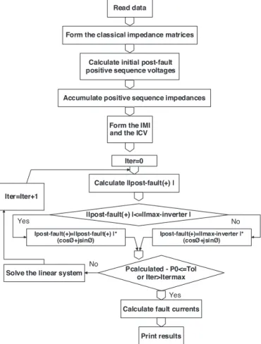
Fig.3.Basicflowchartoftheproposedmethod.
where:PVbeforeisasumrelatedwithpowergenerationPV
beforeofthefault;PVafterisasumrelatedwithpower
gener-ationPVafterofthefault.
Takeforexample,adistributionsystemwhichconsidersthree generationsPVofthesubstationsideandthreegenerationsPV afterthefaultpoint.Inthisexample,thelinediagramisthesame asinFig.2byremovingthedashedlines.Themeshequations allowtowritethefollowinglinearsystemofequations:
−(ZA+ZB+ZC+ZD) −1 0 0 0 0 0 0
−(ZA+ZB+ZC+ZD+ZEQ) 0 0 0 0 0 0 0
−(ZB+ZC+ZD+ZEQ) 0 1 0 0 0 0 0
−(ZC+ZD+ZEQ) 0 0 1 0 0 0 0
−(ZD+ZEQ) 0 0 0 1 0 0 0
−ZEQ 0 0 0 0 1 0 0
−ZEQ 0 0 0 0 0 1 0
−ZEQ 0 0 0 0 0 0 1
I1Vf+
VPV
VPV1
VPV2
Vpv
Vpv1
Vpv2
=
−1+(ZB+ZC+ZD)IPV+(ZC+ZD)IPV1+(ZD)IPV2
−1+(ZB+ZC+ZD+ZEQ)IPV+(ZC+ZD+ZEQ)IPV1+(ZD+ZEQ)IPV2+ZEQ(Ipv+Ipv1+Ipv2)
(ZPV+ZB+ZC+ZD+ZEQ)IPV+(ZC+ZD+ZEQ)IPV1+(ZD+ZEQ)IPV2+ZEQ(Ipv+Ipv1+Ipv2)
(ZC+ZD+ZEQ)IPV+(ZPV1+ZC+ZD+ZEQ)IPV1+(ZD+ZEQ)IPV2+ZEQ(Ipv+Ipv1+Ipv2)
(ZD+ZEQ)IPV+(ZD+ZEQ)IPV1+(ZPV2+ZD+ZEQ)IPV2+ZEQ(Ipv+Ipv1+Ipv2)
(Za+Zpv+Zb+ZEQ)Ipv+(Zb+Zc+ZEQ)Ipv1+(Zc+ZEQ)Ipv2+ZEQ(IPV+IPV1+IPV2)
(Zb+Zc+ZEQ)Ipv+(Zb+Zc+ZEQ+Zpv1)Ipv1+(Zc+ZEQ)Ipv2+ZEQ(IPV+IPV1+IPV2)
(Zc+ZEQ)Ipv+(Zc+ZEQ)Ipv1+(Zc+ZEQ+Zpv2)Ipv2+ZEQ(IPV+IPV1+IPV2)
TheIMIandtheICVareusedtosolvealinearsystemof equa-tionswherethefollowingpost-faultvariables are:current in substation,thevoltageatthefaultpointandvoltagesinthePV grid-connectednodes.
Fig.3presentsthebasicflowchartoftheproposedmethod. ThecalculatedactivepowerisgivenbyEq.(11).
Pcalculated=3.Vpost-fault(+).Ipost-fault(∗ +).Sbase (11)
InbasicflowchartP0isthespecifiedactivepowerforPV gener-ation(MW).
Fig.4.Smalldistributionsystem.
AccordingtoFig.2,thecalculatedfaultcurrentisgivenbyEq.
(8).
IF=I1+IPV+IPV1+IPV2+···+Ipv2+Ipv1+Ipv (12)
C.Simulationofasmallsystem
Inthisparticularitem,wewillgiveanumericalexampleto illustratetheIMICVfaultanalysismethod.
Consider the distribution system shown in Fig. 4. The three-phase short-circuit power and single-phase short-circuit power of the bus 1 are respectively: 4808∠−80◦MVA and
4109∠−80◦MVA. The two transformers are delta-grounded
wye and their data are: T23−138/11.95kV–15MVA−8.68%. T45−11.95/0.22kV-500kVA−5%. The data
distribu-tion lines are: L12: Zpositive=0.1902+j0.4808ohms/km,
Zzero=0.4414+j1.7452ohms/km, distribution line length=
10km, L34: Zpositive=0.1903+j0, 3922ohms/km,
Zzero=0.4359+j1.8540ohms/km,distributionlinelength=0.8km.
Faultphase-earthoccursonbus3(PhaseA),calculate:(1)Thefault current,(2)ThecurrentcontributionofthePVgenerator.
TheinjectedpowerofthePVgeneratoris500kW.The distribu-tionsystembaseis100MVA.
Thecalculationsfollowthebasicflowchart.Thenomenclature isthesameasinFig.2.
1.Calculationofimpedancematrixelements(pu)
Z33positive=0.0136+0.6244i
Z53positive=0.0136+0.6244i
Z33zero=0.0+0.5787i Z53zero=0.0+0.0i
2.Calculationof theinitialpost-fault positive sequencevoltage (pu).
AccordingtoEq.(4):
v
3+=1− Z5,32(Z3,3)+Z30,3+3(0)
3.Accumulationofpositivesequenceimpedances
ZA=0.0136+0.6244i Za=0.1066+10.2197i
4.IMIandICVcalculation
IMI=
−0.1202−10.8441i −1 0 −0.2404−31.6882i 0 0 −0.2268−31.0638i 0 1
ICV=
−0.9995+0.0776i
−0.9991+0.2359i
0.0009+0.2359i
5.Iterativeprocess Tolerance=0.00001pu
Convergenceiterationnumbers=3
IF=0.0316∠−89.3829◦ pu Ipv=0.0051∠−0.1988
◦
pu
4. Validatingtheproposedmethod
Faultcurrentscalculationisakeyfactorindeterminingthetap settingsoftheprotectionrelaysformanypracticalapplications.
The commercial software Simultaneous Fault Analysis (ANAFAS), developed by the Electric Energy Researches Cen-ter (CEPEL) – Brazil, wasused just for verification of the fault currentscalculation.
Thisstudywasperformedontheregionaldistributionsystem thatconsistsofathree-phaseradialdistributionfeederwithurban andruralbranches.ThetestfeederusedwascalledLOC-36andits dataarestatedinAppendix.Thisfeederislocatedinthe distribu-tionsystemoftheEnergyCompanyofCeara–Brazil.LOC-36has 36buses,35branchesanditsthree-phaseshort-circuitpoweris 505.59∠59.10◦MVA.Thetransformersubstationisdelta-grounded
wyeandtheirdataare:69/13.8kV–6%inthesystembase.The single-linediagramofthefeederLOC-36isshowedinFig.5.
Thesimulatedsolarplantswerebasedonphotovoltaicpanels SX120Umodel(manufacturersolarPB).
TheintegrationofPVgenerationunitsaregivenasfollows:330 unitsofgeneratorPVwereinstalledinbus4;110unitsof gen-eratorPVwereinstalledinbus13and990unitsofgeneratorPV wereinstalledinbus19,totalingrespectively,0.957MW(PF=1), 0.319MW (PF=1) and 2.817MW (PF=0.92 inductive) of rated power.Thecomputerusedinthesesimulations,isaDELLcomputer withIntel(R)Core(TM)[email protected],Memory(RAM)
Fig.5.FeederLOC-36diagram.
Fig.6.Overheadlinespacings.
Table1
Faultcurrentresults–bus23.
Faulttype PhasecurrentabsolutevalueANAFAS(pu) PhasecurrentabsolutevalueIMICV(pu)
IA IB IC IA IB IC
LGA 0.590 0 0 0.5915 0 0
LGB 0 0.590 0 0 0.5915 0
LGC 0 0 0.590 0 0 0.5915
LLAB 0.811 0.811 0 0.8166 0.8166 0
LLBC 0 0.811 0.811 0 0.8166 0.8166
LLAC 0.811 0 0.811 0.8166 0 0.8166
LLGAB 0.772 0.901 0 0.7764 0.9076 0
LLGBC 0 0.772 0.901 0 0.7764 0.9076
LLGAC 0.901 0 0.772 0.9076 0 0.7764
Table2
Faultcurrentspercenterrors.
Faulttype Abs(error)(%)
LG 0.25
LL 0.69
LLG 0.57and0.73
LLL 0.67
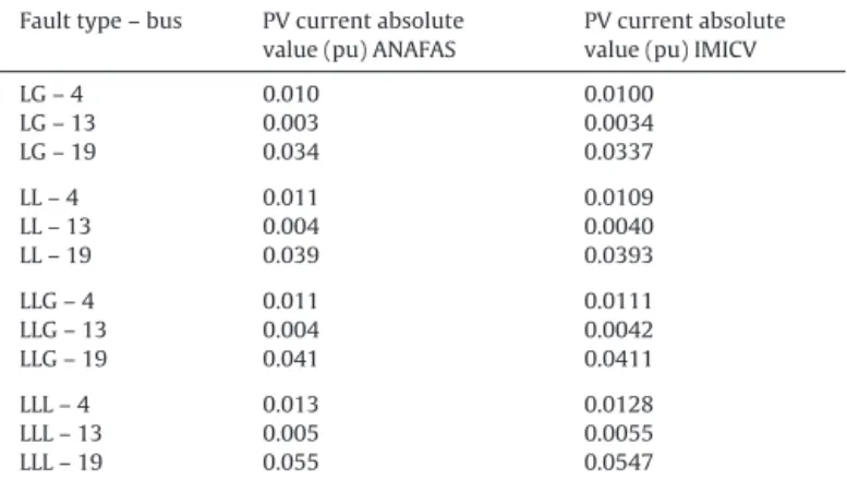
Table3
FaultcurrentsofthePVgenerations.
Faulttype–bus PVcurrentabsolute value(pu)ANAFAS
PVcurrentabsolute value(pu)IMICV
LG–4 0.010 0.0100
LG–13 0.003 0.0034
LG–19 0.034 0.0337
LL–4 0.011 0.0109
LL–13 0.004 0.0040
LL–19 0.039 0.0393
LLG–4 0.011 0.0111
LLG–13 0.004 0.0042
LLG–19 0.041 0.0411
LLL–4 0.013 0.0128
LLL–13 0.005 0.0055
LLL–19 0.055 0.0547
Table4
NumberofiterationsforIMICVconvergenceandCPUtime.
Faulttype Iterationsnumber Totalexecutiontime(s)
LG 4 0.0049
LL 4 0.0048
LLG 5 0.0060
LLL 4 0.0049
8GBand64-bitsOS.TheIMICVfaultanalysismethodwaswrittenin MATLABcode.Afterwards,theresultsobtainedfromANAFASand IMICVwerecompared.
Table1showsacomparisonofthefaultcurrentsonbus23of thefeederLOC-36inbothprogramsdescribedabove.Table2shows thepercenterrorsobtained,respectively,withANAFASandwith theIMICV.
AccordingtoTables 1and 2 theresultsfromIMICV andthe resultsfromANAFAScanbeseentobemuchcloser.Thelargest erroris0.73%.
Table3illustratestheresultsof thefaultcurrentsof thePV generationslocatedonbuses4,13and19.TheresultsofANAFAS softwarereportonlythreedecimaldigits.Oneunderstandsthen thattheresultsfromIMICVandtheresultsfromANAFASalsocan beseentobemuchcloser.Therefore,theIMICVproposedmethod canbeconsideredasvalidated.
Table4presentstheconvergenceiterationnumbersforIMICV andtotal executiontime. Here,thevalueofthespecified toler-ancewas0.00001pu.Furthermore,thelargestiteration number occurredforLLG.Nevertheless,thenumberofiterationsfor conver-gencemadebyANAFASisnotaccessibleinitsresultsfile.Finally, thetotalexecutiontimeoftheIMICVshowsthatthistoolis appro-priatefortheelectricpowerindustryreal-timefaultanalysis.
5. Conclusion
AnovelIMICVfaultanalysismethodisdevelopedinthispaper. Theproposedmethodcanbeusedtosimulateradialdistribution systemwithmultiplePV grid-connected inverters and,also for real-time fault analysis. The numerical results were compared withresultsoftheprofessionalsoftwareANAFASandtheproposed method was validated. Computer simulations show that the
proposed method is efficient, accurate and easy to program. Therefore,thenewmethodcanbeausefultool fortheelectric powerindustry.
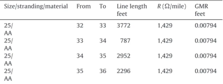
Appendix.
DatafromthefeederLOC-36areshownbelow.
CONDUCTORDATAandLENGTHOFTHEDISTRIBUTIONLINES.
Size/stranding/material From To Linelength feet
R(/mile) GMR feet
266,800/26/7//ACSR 1 2 197 0.385 0.0217
266,800/26/7//ACSR 2 3 656 0.385 0.0217
4/ 6/1 /ACSR
3 4 3083 2.57 0.00437
266,800/26/7//ACSR 3 5 2230 0.385 0.0217
266,800/26/7//ACSR 5 6 525 0.385 0.0217
1/0
ACSR
6 7 3149 1.12 0.00446
4/ 6/1 /ACSR
7 8 5871 2.57 0.00437
4/ 6/1 /ACSR
8 9 1476 2.57 0.00437
4/ 6/1 /ACSR
8 10 2624 2.57 0.00437
4/ 6/1 /ACSR
10 11 1148 2.57 0.00437
4/ 6/1 /ACSR
10 12 2788 2.57 0.00437
4/ 6/1 /ACSR
12 13 2427 2.57 0.00437
266,800/26/7//ACSR 6 14 164 0.385 0.0217
1/0 ACSR
14 15 426 1.12 0.00446
1/0 ACSR
15 16 1148 1.12 0.00446
1/0 ACSR
16 17 492 1.12 0.00446
1/0 ACSR
17 18 262 1.12 0.00446
1/0 ACSR
18 19 230 1.12 0.00446
266,800/26/7//ACSR 14 20 1640 0.385 0.0217
95/ COPPER
20 21 7675 0.356 0.01506
1/0 ACSR
20 22 2493 1.12 0.00446
1/0 ACSR
22 23 886 1.12 0.00446
1/0 ACSR
23 24 394 1.12 0.00446
4/ 6/1 /ACSR
24 25 2624 2.57 0.00437
4/ 6/1 /ACSR
25 26 754 2.57 0.00437
25/ AA
24 27 3542 1,429 0.00794
25/ AA
27 28 5904 1,429 0.00794
25/ AA
28 29 394 1,429 0.00794
25/ AA
29 30 853 1,429 0.00794
25/ AA
30 31 3608 1,429 0.00794
25/ AA
Appendix(Continued)
Size/stranding/material From To Linelength feet
R(/mile) GMR feet
25/ AA
32 33 3772 1,429 0.00794
25/ AA
33 34 787 1,429 0.00794
25/ AA
34 35 2952 1,429 0.00794
25/ AA
35 36 2296 1,429 0.00794
Fig.6showsthespacingdistancesamongphaseconductorsused foroverheaddistributionlines.
References
[1]P.M.Anderson,AnalysisofFaultedPowerSystems.PowerSystemsEngineering Series,IEEEPress,NewYork,USA,1995.
[2]J.DuncanGlover,M.S.Sarma,T.J.Overbye,PowerSystemAnalysis&Designs, 5thed.,ThomsonLearning,Stamford,USA,2011.
[3]J.J.Grainger,W.D.StevensonJr.,PowerSystemAnalysis,McGraw-Hill,Inc.,New York,USA,1994.
[4]G.M.Masters,RenewableandEfficientElectricPowerSystems,JohnWiley& Sons,NewYork,USA,2004.
[5]H.Hooshyar,M.E.Baran,Faultanalysisondistributionfeederswithhigh pen-etrationofPVsystems,IEEETrans.PowerSyst.28(August)(2013)2890–2896.
[6]C.A.Plet,T.C.Green,Faultresponseofinverterinterfaceddistributed gen-eratorsingrid-connectedapplications,Electr.PowerSyst.Res.106(2014) 21–28.
[7]T.-C.Ou,Anovelunsymmetricalfaultsanalysisformicrogriddistribution sys-tems,Int.J.Electr.PowerEnergySyst.43(2012)1017–1024.
[8]M.E. Baran, I. El-Markaby, Fault analysis on distribution feeders with distributed generators, IEEE Trans. Power Syst. 20 (November) (2005) 1757–1764.
[9]O.M.Toledo,D.OliveiraFilho,A.S.A.C.Diniz,J.H.Martins,M.H.M.Vale, Method-ologyforevaluationofgrid-tieconnectionofdistributedenergyresources– casestudywithphotovoltaicandenergystorage,IEEETrans.PowerSyst.28 (2013)1132–1139.
[10]T.-C. Ou, Groundfault currentanalysis witha direct buildingalgorithm for microgrid distribution, Int. J. Electr. Power Energy Syst. 53 (2013) 867–875.
[11]S.P.Pokharel,S.M.Brahma,S.J.Ranade,Modelingandsimulationofthreephase inverterforfaultstudyofmicrogrids,in:NorthAmericanPowerSymposium (NAPS),2012.
[12]F.Ding,K.A.Loparo,C.Wang,Modelingandsimulationofgrid-connectedhybrid AC/DCmicrogrid,PowerEnergySoc.Gen.Meet.(2012)1–8.
[13]E.Muljadi,M.Singh,R.Bravo,V.Gevorgian,Dynamicmodelvalidationof PV invertersunder short-circuit Conditions, GreenTechnol.Conf. (2013) 98–104.
[14]H.Ravindra,M.O.Faruque,P.McLaren,K.Schoder,M.Steurer,R.Meeker,Impact ofPVondistributionprotectionsystem,in:NorthAmericanPowerSymposium (NAPS),2012.