INTRODUCTION
PLAnetary Transits and Oscillations of stars (PLATO) is a project from the Cosmic Vision program by the European Space Agency (ESA), which is currently in phase M3 (launch scheduled for 2022). A large-scale photometer composed of 34 cameras is used, whose objective is to detect and characterize extrasolar planets and their host stars by using the transit method (Catala and PLATO consortium, 2008). This multi-camera approach will jointly observe the same region of the sky.
There is a front-end electronic system (FEE) associated with each camera, which is responsible for image digitization and for their sending to the digital processing unit (DPU) of the satellite. The satellite has 16 normal DPU (N-DPUs) for mining scienti¿c data from the images and two fast ones (F-DPUs) for interfacing with fast cameras. For the FEE and DPU communication, the SpaceWire and remote memory access protocols (RMAP) were selected (ESA, 2008), both of which were widely used in several space missions (Parkes and Ferrer, 2010).
The project involves the creation of a dedicated device, which is capable of simulating the behavior of a normal FEE (NFEE) with the main objective of testing the proposed architecture for the PLATO satellite and of validating, in a near future, the DPU¶s Àight software. The system was implemented in VHSIC hardware description language (VHDL) and embedded into a ;ilinx ;CVL;0 ¿eld-programmable gate array (FPGA) (Xilinx, 2011).
PLATO ARCHITECTURE
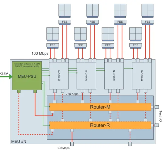
The architecture proposed for the PLATO satellite (Larque and Plasson, 2011) has 34 independent telescopes, each made up of an optical unit and a camera. From the 34 cameras, 32 are normal ones (N-Cameras), meant for scienti¿c use and delivery of high-resolution photometry (81 Mpx/Camera, 1 px = 16 bits) at 25-second intervals. The two remaining cameras (F-Cameras) are used in the satellite’s control loop at 2.25-second intervals (41 Mpx/camera).
The 32 scienti¿c-purpose N-Cameras were arranged in the satellite in four subgroups of eight cameras (Fig. 1). The two fast cameras work independently and have each a dedicated processing unit.
The charge-coupled device (CCDs) used in the mission have two zones: the image zone, which is made up of detec-tors, and the memory zone, used for the storage of temporary images. The memory zone has two access points, thus enabling simultaneous readings in different areas.
Each camera is equipped with its own four-CCD-wide matrix, each containing 4,520 lines by 4,535 pixels. A FEE is coupled to each camera and is responsible for controlling CCD operation and communicating with the DPU, sending images and status information (housekeeping). The FEE also propagates time information to the DPU, which uses these data for image processing.
Image delivery occurs every 6.25 seconds, alternating the CCDs at every cycle. The process is handled using two SpaceWire links that operate each at 100 Mbps. Each link transfers half of a CCD’s image (right and left sides) simultaneously, increasing, thus, the system’s general data signaling rate to 200 Mbps.
The RMAP was chosen for image transmission. This protocol allows writing and reading from a memory unit
Electronic Simulator of the PLATO Satellite Imaging System
Rafael Corsi Ferrão*, Sergio Ribeiro Augusto, Tiago Sanches da Silva, Vanderlei Cunha Parro Instituto Mauá de Tecnologia – São Caetano do Sul/SP – Brazil
Abstract: This paper described an architecture that is able to emulate the behavior of the imaging transfer system proposed for the PLATO satellite – PLAnetary transits and oscillations of stars. It was conceived to accurately repre-sent Àight operation as to validate the satellite digital processing unit on its development phase. 'etails related to the PLATO mission, its architecture, and the implementation technical details are presented in this article.
Keywords: SpaceWire, Remote Memory Access Protocol, PLAnetary Transits and Oscillations of stars, Ground support equipment, Hardware description languages.
Received: 08/05/12 Accepted: 06/09/12 *author for correspondence: [email protected]
through a SpaceWire node. Image transmission takes place in a manner which is transparent to both nodes, that is, without demanding processor intervention.
Delivery is carried out by a RMAP command that encap-sulates half of a CCD’s line. This command is sent without data veri¿ cation or acknowledgement. Control commands sent from the DPU to the FEE, on the other hand, are provided with both of these capabilities.
A total of 16 Normal-DPUs execute onboard of the satel-lite routines for mining scienti¿ c data from the images stored in the memories. These routines run in parallel with image reception. Each N-DPU is responsible for data processing sent by two N-FEEs.
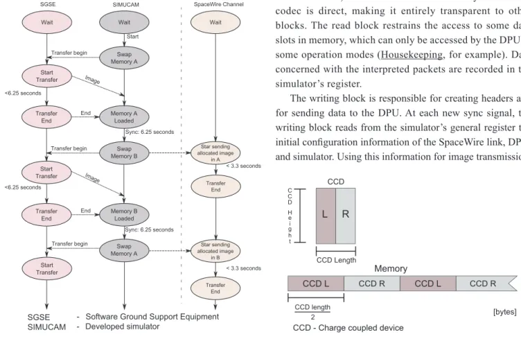
The complete transfer of a quarter of an image (one CCD) must last at most 3.3 seconds, leaving enough spare time for the complete execution of the image data mining. Image transfer happens as depicted in Fig. 2.
ARCHITECTURE PROPOSED FOR THE SIMULATOR
The proposed platform (SimuCam) emulates a NFEE capable of testing half of a Normal-DPU (each NDPU takes
care of two NFEE), sending new images at each sync signal. The objectives are to have a system capable of dynamically test the DPU’s embedded software and to validate the archi-tecture proposed for the mission.
The architecture shown in Fig. 3 has as its cornerstone two volatile memories used for temporary storage of the image to be transmitted. These memories work complementarily and are used as data buffers. Their operation may be described as follows: while a memory is being loaded with a new image that will be transferred, the other one is being read and its data sent by the simulator to the DPU. At the next sync signal, the Figure 1. Optic bank.
Figure 2. One cycle of the Plato charge-coupled device transfer
memories are switched, and a new picture is loaded into the memory that was recently read. Figure 4 illustrates the process.
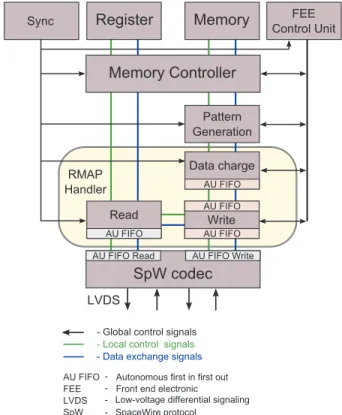
Image loading into memory is performed through a high-speed communication path (USB) between the workstation and the memory controller (Fig. 5), being the latter responsible for managing memory access and access to the simulator’s internal register.
The SpW/RMAP block is responsible for the interface with the SpaceWire codec and for the creation and interpretation
of RMAP commands. Implemented according to the ECSS-E-ST-50 standard (ESA, 2008), the block allows the DPU to read and modify the simulator’s internal registers, changing in this way its behavior during operation. It also creates and automatically sends RMAP writing commands containing the image that will be transferred, in addition to extra information in each command (information about the line and the CCD). Housekeeping data are sent separately, after the end of trans-mission of each CCD.
The RMAP handling has two internal interfaces, read and write, which take care of generating and propagating RMAP packets, as well as of interpreting RMAP commands sent by the DPU.
These interfaces run in parallel, allowing a writing command to be executed in local memory, while images are being transferred by the write block. If a write block interprets a command with acknowledgemen t or a read command, the answer is placed on a response queue (with a priority level inferior to that of the images). Only after the end of the image data transmission, the answers are dispatched.
The read block is a Mealy state machine that interprets, reads or writes commands (with or without veri¿ cation and/or answer). Communication to memory and to the codec is direct, making it entirely transparent to other blocks. The read block restrains the access to some data slots in memory, which can only be accessed by the DPU in some operation modes (Housekeeping, for example). Data concerned with the interpreted packets are recorded in the simulator’s register.
The writing block is responsible for creating headers and for sending data to the DPU. At each new sync signal, the writing block reads from the simulator’s general register the initial con¿ guration information of the SpaceWire link, DPU, and simulator. Using this information for image transmission,
the RMAP header con¿ gurations are automatically changed at each new command, without the need for external control.
Data sent to the DPU are previously loaded into an autono-mous ¿ rst in ¿ rst out (FIFO) device (Haywood, 2004) by the data charge block, which addresses the memory controller by taking into account memory-image allocation. This charging procedure is necessary so that the memory controller can be shared with more than one RMAP writing block. Figure 6 illustrates the blocks interfaces of a single RMAP handling.
The pattern generation block interprets addresses sent by data charge and creates patterns that are used for tests and validation.
The simulator has an internal register bank that contains all of its con¿ gurations. These registers are shared by all blocks, and the con¿ gurations can be changed both by the USB interface and by the RMAP writing command sent by the DPU to the simulator.
A TimeCode (ESA, 2008) is used for the propagation of time and is sent automatically whenever a sync signal is received, ensuring time propagation required by the applica-tion. The TimeCode points out to the DPU the beginning of a new transmission. Besides, it is also used to indicate the CCD (zero, one, two, three) being transferred.
The sync block propagates or creates reference signals (6.25 and 25 seconds) used by all other blocks for synchronism and internal update.
The FEE control is a state machine that controls memory access to both the RMAP reading and loading blocks. It also oversees the memory exchange operation and takes care of arbitrating reading accesses, ensuring that both RMAP memo-ries always have their internal buffers suf¿ ciently full so that the image transmission does not remain idle, hence raising the system’s ef¿ ciency. The control logic takes into consideration that the reading operation executed by the RMAP block is performed in bursts (of con¿ gurable size), raising the ef¿ -ciency of the access to the system’s SDRAM memory.
A codec provided by Commissariat à l’Énergie Atom-ique (CEA) was used for applications in Xilinx Virtex5 chips (Frédéric and CEA, 2008). It implements all protocol speci¿ cations with low-chip resource usage. Furthermore, it supports a maximum transmission frequency of 320 Mbps and has a 32-byte reception FIFO.
Several system and simulator characteristics can be modi¿ ed, enabling the simulator to be as generic as possible. The following con¿ gurations can be made:
ȩ simulator parameters: they con¿ gure the simulator’s operation and its operation mode. Among others, CCD reading direction (clockwise or counter-clockwise) can be selected. Likewise, error insertions into RMAP packets and internal and external synchronisms (and synchronism period) can be con¿ gured
ȩ housekeeping: related to SDRAM memory space allocation, data quantity, and RMAP protocol con¿ gurations
ȩ CCD description: it occupies itself with CCD physical information, such as size, pre-scan columns, semi-ring rows, analog to digital converter (ADC) speed and resolution, delays between lines, and RMAP protocol con¿ gurations used for sending the image to the DPU.
IMPLEMENTATION AND TESTS
The GR-PCI-XC5V board from AeroÀ ex Gaisler (Gaisler, 2011) was used for the implementation of the simulator SimuCam. This board has a FPGA Virtex5 XC5VLX50 core from Xilinx, as well as FLASH, SRAM, and SDRAM memories.
The hardware proposed for the application was described in VHDL in order to run operations in parallel, aiming at the global increase in performance of the simulator.
All blocks having an interface between FIFOs were implemented using the concept of autonomous FIFO, dispensing data À ow control between blocks. The chip’s internal RAM was used as memory for the FIFOs.
All blocks within this project had their logic and functionality tested with test benches exclusively created for each block. A global system simulation was performed verifying system integrity and timing.
Tests were carried out in the Paris Observatory, in Meudon jointly with LESIA (Laboratoire d’Études Spatiales et d’Instrumentation en Astrophysique), which is responsible for the speci¿ cation of the satellite’s architecture. The test scenario can be seen in Fig. 7.
The simulator was connected via two SpaceWire links to a GR-RASTA system (Gaisler, 2011) enclosing a LEON2 processor, left in charge of simulating a half normal DPU, and a Debug System Unit (DSU) to perform ¿ rmware debugging. The tests involved sending data (patterns) from the simula-tor to LEON2’s memory zone, which was responsible for verifying data integrity. Timing imposed by the speci¿ cation was tested with a SpaceWire link analyzer (STAR-Dundee, 2012). A Software Ground Support Equipment (SGSE) was developed to control the SimuCam.
The sent patterns were prede¿ ned and were generated inside the simulator with the pattern generation block (Fig. 6).
Figure 7. Test bench.
CONCLUSIONS
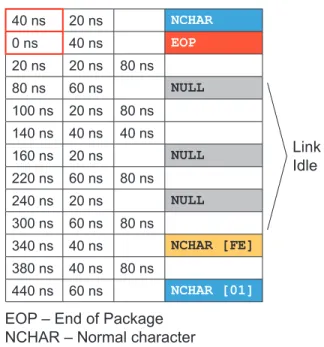
With the aid of the proposed system, it was possible to send an entire image from the SimuCam in only 2.93 seconds, better than the originally time proposed, i.e., 3.3 seconds (Table 1). The SpaceWire links attained a 99.93% utilization rate, being held idle for 240 ns for every half line sent (between RMAP commands) as shown in Fig. 8. The use of the platform at a higher speed of the SpaceWire link (200 Mbps) was also possible without incurring ef¿ ciency loss in the link.
The entire implementation of the architecture (SpaceWire codec RMAP handling memory controller USB handling FEE control, and internal register) used 45% (13314) of the
40 ns 20 ns NCHAR
0 ns 40 ns EOP
20 ns 20 ns 80 ns
80 ns 60 ns NULL
100 ns 20 ns 80 ns
140 ns 40 ns 40 ns
160 ns 20 ns NULL
220 ns 60 ns 80 ns
240 ns 20 ns NULL
300 ns 60 ns 80 ns
340 ns 40 ns NCHAR [FE]
380 ns 40 ns 80 ns
440 ns 60 ns NCHAR [01]
Link Idle
EOP – End of Package NCHAR – Normal character
Figure 8. Transfer analysis of the RMAP protocol with the least time
between two lines using Stardundee’s SpaceWire analyzer. Table 1. Comparative table between the real NFEE and the
obtained timing from implemented SimuCam.
Con¿ guration NFEE SimuCam Unit
CCD width 4,510 4,510 Pixels
CCD height 4,510 4,510 Pixels
Smearing rows 10 10 Rows
Prescan per CCD
output 25 25 Pixels
Pixel coding 16 16 Bits
ADC Speed 4 6.97 MHz
SpaceWire links 2 2 Number
SpaceWire bit rates 100 100 Mbps
Full CCD total
transfer time 3.3 2.93 seconds
Package size + 16
bytes RMAP header 4,576 4,576 Bytes
Instantaneous data
rate for 1 link 80 100 Mbps
Averaged data rate over full CCD transfer
70.5 99.93 Mbps
NFEE: normal front end electronic
FPGA’s lookup table (LUTs) and 22% (6,568) of its slice registers, enabling the implementation of two simulators in the same chip.
The proposed architecture from the system is Àexible and suitable to be used again in other projects. Since it was devel-oped with emphasis on recon¿gurability, this system allows the dynamic modi¿cation of its behavior through changes in several simulator values, such as CCD size, ADC rate, RMAP protocol con¿gurations, reading direction, among others.
ACKNOWLEDGEMENTS
The authors thank the National Council for Scienti¿c and Technological Development – Brazil (CNPq) for the ¿nancial support, Mauá Institute of Technology (IMT) and LESIA for the collaboration opportunity.
REFERENCES
Catala, C. and PLATO consortium, 2008, “PLATO PLAnetary Transits and Oscillations of stars – A study of exoplanetary systems, proposal”, Vol. 1, Retrieved in 20 Feb. 2011, from http://www.lesia.obspm.fr/perso/claude-catala/ plato_web.html.
ESA Requirements and Standards Division, 2008, “SpaceWire links, nodes, routers and networks ECSS-E-ST-50-11C”.
Frédéric, P. and CEA, 2008, “Commissariat à l’Énergie Atomique et aux énergies alternatives”, IP SpaceWire Data Sheet.
Gaisler, A., 2011, “AeroÀex Gaisler”, Retrieved in 21 Feb. 2011, from http://www.gaisler.com/cms/.
Haywood, S., “Autonomous Cascadable Dual Port FIFO”, Retrieved in 2004, from http://www.spacewire.co.uk/ auto_¿fo.html.
Larque, T. and Plasson, P., 2011, “DPU FEE interface requirement document”, PLATO DPS TS 138 THALES, Vol. 11.
Parkes, S. and Ferrer, A., 2010, “SpaceWire-D: Deterministic Data Delivery with SpaceWire”, In: Proceedings of the 3rd International SpaceWire Conference, St. Petersburg.
STAR-Dundee, 2011, “SpaceWire Link Analyser Mk2”, Retrieved in 20 Mar. 2012, from http://www.star-dundee.com/ products.