INTRODUCTION
At the end of the 1990s, among the Brazilian sounding rockets, the VS-40 was presented as one that provides the best conditions for experiments in microgravity (Ribeiro, 1999). Space systems are complex, i.e., their behavior is governed by many distinct but interacting physical phenomena, and multidisciplinary, requiring balance among competing objectives related to safety, reliability, performance, operability, and cost (Rowell and Korte, 2003). Over time, advances in the engineering of complex systems have allowed to more quickly identify feasible solutions and exploit the synergy among the design disciplines (Rowell and Korte, +RZHYHUWKH96KDVQRWEHHQEHQH¿WHGE\VXFK advances yet. The interactions between the design disciplines of the VS-40 were processed in a sequential order, in which those disciplines that act early in the conceptual design establish constraints on the others that follow later, leading to a concept without regarding the trade-offs that may exist between the design objectives. The plausible consequence of such sequential methodology is a suboptimal design with
respect to the entire project, promoted by low synergy between the design disciplines.
6LQFH ZKHQ WKH ¿UVW 96 ZDV ODXQFKHG WKH methodology that allows exploiting the synergy between its design disciplines has not been used yet for Brazilian sounding rockets. A methodology called multidisciplinary design optimization (MDO) replaces the traditional sequential methodology by synergic interactions between the design disciplines, promoting the overall gain in product’s performance, decreasing the design time (Floudas and Pardalos, 2009).
Why should the VS-40 be revised? It promises the best conditions for microgravity experiments, but not widely launched yet such as the VSB-30, also a Brazilian sounding rocket, so that it could be more studied, and perhaps improved E\FRQVLGHULQJFROOHFWHGÀLJKWGDWD7KH96ZDVUHFHQWO\ PRGL¿HGDWWKH*HUPDQ$HURVSDFH&HQWHU'/5LQRUGHUWR SURYLGHWKHUHTXLUHGVWDELOLW\IRUDVSHFL¿FPLVVLRQEHFDXVH it was not originally designed for carrying a payload with exposed canards, indicating that its design can be altered, if QHFHVVDU\WREHQH¿WLWVVWDELOLW\DQGSHUKDSVLWVSHUIRUPDQFH /DVWO\LWKDVQRWEHHQEHQH¿WHGE\DGYDQFHVLQWKHHQJLQHHULQJ of complex systems, and it may have some subsystems that could be improved regarding its next launches at Brazilian
Multidisciplinary Design Optimization of Sounding Rocket Fins
Shape Using a Tool Called MDO-SONDA
Alexandre Nogueira Barbosa1*, Lamartine Nogueira Frutuoso Guimarães2 1,QVWLWXWRGH$HURQiXWLFDH(VSDoR±6mR-RVpGRV&DPSRV63±%UD]LO
2,QVWLWXWRGH(VWXGRV$YDQoDGRV±6mR-RVpGRV&DPSRV63±%UD]LO
Abstract:0XOWLGLVFLSOLQDU\GHVLJQRSWLPL]DWLRQLVDSURPLVLQJ¿HOGLQDHURVSDFHHQJLQHHULQJ+RZHYHUDGYDQFHVLQWKLV ¿HOGKDYHQRWEHHQDSSOLHG\HWWRLPSURYH%UD]LOLDQVRXQGLQJURFNHWVVXFKDVWKH967KHUHIRUHWRJLYHDSHUVSHF WLYHRIWKHPXOWLGLVFLSOLQDU\GHVLJQRSWLPL]DWLRQLQWKLVFRQWH[WWKLVZRUNSUHVHQWHGDFDVHVWXG\RIWKLVURFNHWZKLFK FRQVLVWVRIWKHVKDSHRSWLPL]DWLRQRILWV¿QV7RDFKLHYHWKLVJRDODVSHFLDOWRROFDOOHG0'2621'$ZKLFKLVWKHPDLQ FRQWULEXWLRQRIWKLVZRUNZDVGHYHORSHG,WVFXUUHQWYHUVLRQLQWHUDFWVZLWKWZRKLJK¿GHOLW\H[HFXWDEOHFRGHVRQHRI DHURG\QDPLFVDQGDQRWKHURIWUDMHFWRU\H[SORLWLQJWKHV\QHUJ\EHWZHHQERWKGLVFLSOLQHV7KH0'2621'$LVEDVHGRQ DPXOWLREMHFWLYHJHQHWLFDOJRULWKPZKRVHUHDORSHUDWRUZDVRULJLQDOO\GHVLJQHGLQWKLVZRUN%\XVLQJWKHSURSRVHGWRRO LWZDVIRXQGWKDWWKHGUDJGXHWRWKHURFNHW¿QVFRXOGEHUHGXFHGXSWRZLWKRXWLQFUHDVLQJWKHFKDQFHVRIDGYHUVH HIIHFWVWKDWFRXOGOHDGWRXQVWDEOHEHKDYLRUV
Keywords:6RXQGLQJURFNHW5RFNHW¿QGHVLJQ0XOWLGLVFLSOLQDU\GHVLJQRSWLPL]DWLRQ0XOWLREMHFWLYHJHQHWLFDOJRULWKPV
territory carrying the Sub-orbital SARA, a Brazilian platform for microgravity experiments.
Motivated by a search for VS-40 improvements, the use of the MDO was introduced in Brazilian sounding rockets. Therefore, the objective of this paper was to provide a perspective of the MDO application in this context based on a case study of the VS-40. As case study, the shape optimization RI WKH 96 ¿QV ZDV SURSRVHG LQ RUGHU WR LPSURYH LWV SHUIRUPDQFHE\UHGXFLQJWKHGUDJGXHWRWKH¿QVZLWKRXW increasing the chances of adverse effects that could lead to unstable behaviors. To perform the optimization, a computer tool called MDO-SONDA (MDO of Sounding Rockets), which was developed by Alexandre Nogueira Barbosa, was XVHG0'2621'$SUHVHQWDWLRQLQWKHOLWHUDWXUHZDV¿UVW introduced by this paper.
SOUNDING ROCKETS AND MICROGRAVITY ENVIRONMENT
Sounding rockets, such as the VS-40, are characterized by WKHLUDSSOLFDWLRQDQGÀLJKWSUR¿OH$FFRUGLQJWR0RQWHQEUXFN HWDO (2001), such rockets are constituted of solid fueled motors and a payload that carries instruments to take measurements DQGSHUIRUPVFLHQWL¿FH[SHULPHQWVGXULQJDSDUDEROLFÀLJKW Thus, the sounding term means taking measurements.
In comparison with the VSB-30, the VS-40 bi-stage can provide a wide exposure to the microgravity environment, characterized by a condition where an object is subjected WRDJIRUFHOHVVWKDQȝJ/D1HYHDQG&RUUrD-U achieved by moving in free fall, where there are no forces other than gravity acting on the object.
Payloads carried by rockets achieve the microgravity environment after the burnout of the rocket when the thrust force is zero and the payload is above the atmosphere. It is assumed that the Kármán line, at 100 km above the seawater surface, might be used as a reference for microgravity H[SHULPHQW SXUSRVHV WR GH¿QH WKH ERXQGDU\ EHWZHHQ WKH atmosphere and the outer space, from which the atmosphere becomes so thin that the drag force could be neglected.
FACTS ABOUT THE VS-40
In spite of the fact that the VS-40 provides more exposure to microgravity than the VSB-30, since the 21st century began, rather than the VS-40, the VSB-30 has been most frequently XVHG IRU PLFURJUDYLW\ H[SHULPHQWV *DUFLDHW DO, 2011). &HUWDLQO\EHFDXVHWKH96%KDVPHWPLVVLRQUHTXLUHPHQWV
for microgravity experiments with an advantage, the payload recovery operation associated with the VSB-30 is less costly WKDQZLWKWKH96ZKRVHVSODVKGRZQLVDSSUR[LPDWHO\¿YH times more distant from the continent-ocean boundary than the VSB-30, demanding more autonomy for the recovery means.
From 2004 to 2010, ten VSB-30 campaigns were successfully performed, three of them in the Brazilian territory *DUFLDHWDO, 2011). In contrast to the VSB-30, three VS-40 campaigns has occurred so far, two of them in the Brazilian WHUULWRU\WKH¿UVWRQHLQ6DQWD0DULDFDPSDLJQ)LJD DQGWKHVHFRQGRQHLQ/LYUDPHQWRFDPSDLJQ)LJE ERWKDWWKH$OFkQWDUD/DXQFK&HQWHU&/$LQ0DUDQKmR,$( 2Q-XQHDPRGL¿HG96FDOOHG960 carrying the Sharp Edge Flight Experiment (SHEFEX) II (Weihs HW DO D D *HUPDQ SURMHFW ZDV VXFFHVVIXOO\ launched at the Andøya Rocket Range in Northern Norway '/5 DQG LW EHFDPH WKH ¿UVW 96 RSHUDWLRQ LQ DQRWKHUFRXQWU\)LJF7KH960¿QVVKDSH)LJF LV VLJQL¿FDQWO\ GLIIHUHQW IURP WKH WZR SUHYLRXV 96 )LJVDDQGE7KHQHZ¿QVZHUHGHVLJQHGDQGFRQVWUXFWHG IRU6+()(;,,DW'/5GXHWRWKHQHHGRIH[WHQGHG¿QVWR compensate for the aerodynamic effects of the small canards at the payload, as can be seen in Fig. 1c (Weihs HWDO, 2008).
In 1997, a recovery orbital platform called SARA for supporting short-orbital experiments in microgravity environment was proposed (Moraes and Pilchowski, 1997). ,Q FRPSDULVRQ ZLWK D VXERUELWDO ÀLJKW ZKLFK SURYLGHV D few minutes of microgravity conditions, an orbital one can provide more than ten days before reentering the Earth’s DWPRVSKHUH7KH6SDFH&DSVXOH5HFRYHU\([SHULPHQW65( ZKLFKLVDQ,QGLDQVSDFHFUDIW¿UVWODXQFKHGLQLVDYHU\
(a) (b) (c) Sources: (a) and (b) Institute of Aeronautics and Space, Brazil;
similar example of such a kind of platform (Reddy, 2007). $OVRDQH[DPSOHLVWKH5(;)UHH)O\HUWKH*HUPDQSURSRVDO for application of SHEFEX derived technology, which is a reusable orbital return vehicle for experiments under microgravity conditions (Weihs HWDO, 2008b).
Thereafter, a platform called Sub-orbital SARA, which is part of the road map to achieve the orbital mission purpose of this platform, has been constructed to be launched by a VS-40, supporting an experimental module to be exposed to PLFURJUDYLW\HQYLURQPHQW/D1HYHDQG&RUUrD 7KH96ZDVRULJLQDOO\GHVLJQHGIRUÀLJKWTXDOL¿FDWLRQ of the S44 motor, which constitutes the fourth stage of the %UD]LOLDQODXQFKYHKLFOH9/63HUHLUDDQG0RUDHV-U ,QZKHQWKH¿UVW96ZDVODXQFKHGWKH0'2 methodology had recently been presented.
7KHVKDSHRSWLPL]DWLRQRIWKH96¿QVZLOOEHSUHVHQWHG as a case study using such methodology to demonstrate its application in the context of Brazilian sounding rockets. However, before presenting the results of the optimization, the main aspects of the MDO-SONDA will be further depicted.
MULTIDISCIPLINARY DESIGN OPTIMIZATION OF SOUNDING ROCKETS
The MDO-SONDA was conceived to exploit the synergy between the design disciplines of sounding rockets. Among them, those that use physics-based engineering models are: propulsion, aerodynamics, heating, structures, controls, and trajectory. Its current version interacts in batch mode with WZR KLJK¿GHOLW\ H[HFXWDEOH FRGHV RQH RI DHURG\QDPLFV and another of trajectory. Thus, it can exploit the synergy between these two disciplines. Interacting with at least two disciplines makes the MDO-SONDA able to demonstrate the MDO methodology. Besides, it can support multiobjective problems. It can also investigate the trade-offs between the design objectives.
The current version is only prepared for optimization of WKHVKDSHRIURFNHW¿QV+RZHYHULWLVDQREMHFWRULHQWHGFRGH ZULWWHQLQ&WKDWSURYLGHVVSHFL¿FIRUPVFODVVHVDQGREMHFWV to structure proper interfaces for further studies, including the shape optimization of other rocket subsystems, such as DGGLWLRQDOVHWRI¿QVQRVHIDLULQJSURWXEHUDQFHVDQGFRQLFDO transitions between rocket stages of different diameters.
The main aspects of the MDO-SONDA are architecture, inputs, outputs, optimization algorithm, and how to proceed with the optimization.
Architecture
The architecture of the MDO-SONDA is described in two parts: the interaction between the objective function and WZRKLJK¿GHOLW\H[HFXWDEOHFRGHVRQHRIDHURG\QDPLFVDQG another of trajectory (Fig. 2a); and, the interaction between the optimization algorithm and the objective function (Fig. 2b). 7KHKLJK¿GHOLW\H[HFXWDEOHFRGHVDUHPLVVLOHGDWFRPDQG rocket simulation (ROSI).
The missile datcom is a widely used semi-empirical aerodynamic prediction code, which estimates aerodynamic forces, moments, and stability derivatives for a wide range RIPLVVLOHFRQ¿JXUDWLRQVDVDIXQFWLRQRIWKUHHDWPRVSKHULF descriptors: Mach number, altitude, and angle of attack (Sooy and Schmidt, 2005). Its original version was developed in )2575$1E\WKH0F'RQQHOO'RXJODV&RUSRUDWLRQ/DWHU the FORTRAN 90 version was documented by the U.S. Air Force (Blake, 1998).
The ROSI is also a FORTRAN code. It computes the motion of a rigid body in a three-dimensional space, considering also its rotation in yaw, pitch, and roll axes (Ziegltrum, *RPHV,WVRULJLQDOYHUVLRQZDVGHYHORSHGE\ '/5=LHJOWUXP6LQFHWKHVWKH526,KDVEHHQ successfully used for the trajectory calculation of Brazilian sounding rockets.
Objective function
ROSI software
Trajectory discipline Missile DATCOM
software
Aerodynamic discipline
interacts with interacts with 2nd 1st step
Design variables
Evaluation of each cost
function Optimization
algorithm
assigns values to feeds
feed
calls
returns Objective function
2nd
3rd
4th
5th 1st step
(a) (b)
The MDO-SONDA calls the executable codes in batch mode, which means to run to completion without manual intervention. The missile datcom provides to ROSI the IROORZLQJ DHURG\QDPLF SURSHUWLHV GUDJ FRHI¿FLHQW &D), QRUPDOIRUFHFRHI¿FLHQWGHULYDWLYHZLWKDQJOHRIDWWDFN&1Į),
SLWFKLQJPRPHQWFRHI¿FLHQWGHULYDWLYHZLWKDQJOHRIDWWDFN &0ĮSLWFKLQJPRPHQWFRHI¿FLHQWGHULYDWLYHZLWKSLWFKUDWH
&Mq UROOLQJ PRPHQW FRHI¿FLHQW GHULYDWLYH ZLWK UROO UDWH &lp), and center of pressure (Xcp).
,QDGGLWLRQ526,XVHVWKHUROOGULYLQJFRHI¿FLHQW&Oį&lp DQG&OįDUHSDUDPHWHUVRIHDFKVLQJOH¿QWRGHWHUPLQHWKHUROO
rate of the rocket. Unfortunately, the missile datcom does not SURYLGH&OįEXWSURYLGHVWKHUROOLQJPRPHQWFRHI¿FLHQW&l). To use missile datcom calculation indirectly, it is assumed that &lIRUDYHU\VPDOOGHÀHFWLRQDQJOHRIHDFK¿Qį FDQ EHXVHGWRHVWLPDWH&Oį(Eq. 1):
.
C
C
C
0 01
ll 1
2
2
c
,
d
=
d (1)
The MDO-SONDA manages the process of each executable code, writes their inputs, and reads their outputs, coordinating their interaction. During the optimization loop, if they freeze for any reason, their processes are, automatically, killed and restarted but with different inputs. First, the MDO-SONDA interacts with missile datcom, obtaining the aerodynamic FRHI¿FLHQWV7KHQLWZULWHVWKHFRHI¿FLHQWVLQWRWKHLQSXW¿OH of ROSI, which also receives the mass and inertia properties of the rocket, i.e., the changes of mass, center of gravity, moment of inertia and product of inertia, computed by the MDO-SONDA due to spent stage separations, system releases DQGSURSHOODQWFRQVXPSWLRQDORQJWKHURFNHWÀLJKW
2QHPDMRUEHQH¿WRIWKH0'2621'$LVWRSURYLGHD user-friendly interface to insert input values and to check, graphically, outputs of both missile datcom and ROSI. It also SURYLGHVWKHYLVXDOL]DWLRQRIWKHLQSXW¿OHRIHDFKH[HFXWDEOH code, which is automatically generated to make sure that there is not any apparent mistake.
Inputs
The MDO-SONDA inputs can be grouped in three parts. 7KH¿UVWRQHFRQVLVWVRILQLWLDOFRQGLWLRQVÀLJKWHYHQWVDQG URFNHWGH¿QLWLRQVZKLFKSURYLGHWKHHQWULHVWRHVWLPDWHWKH DHURG\QDPLFFRHI¿FLHQWVDQGWRVLPXODWHWKHURFNHWWUDMHFWRU\ The second are the elements of the optimization problem: GHVLJQREMHFWLYHVYDULDEOHVDQGFRQVWUDLQWV/DVWO\WKHWKLUG ones are the optimization algorithm settings. With respect to
WKH¿UVWSDUWW\SLFDOÀLJKWHYHQWVDUHVWDJHLJQLWLRQEXUQRXW spent stage separation, nose fairing ejection, and system release. Such events divide the trajectory calculation into phases, since WKH\SURGXFHDEUXSWFKDQJHVLQWKHURFNHWFRQ¿JXUDWLRQ)RU LQVWDQFHWKHDHURG\QDPLFFRHI¿FLHQWVDUHJLYHQDVDIXQFWLRQ of Mach and altitude for each change in rocket geometry, due to the separation of its parts, and jet plume, due to switching a motor on and off. Each phase is characterized by rocket GH¿QLWLRQV ZKLFK GHQRWH WKH SKDVH FRQ¿JXUDWLRQV RI WKH URFNHW7KXVIRUHDFKRQHURFNHWGH¿QLWLRQVDUHJHRPHWU\ of the body, propulsion data, and mass and inertia properties of each subsystem that still remains in the rocket during the ÀLJKW8VLQJWKH+X\JHQV6WHLQHUWKHRUHPWKH0'2621'$ computes the total mass and inertia properties of each phase FRQ¿JXUDWLRQRIWKHURFNHW
Outputs
The MDO-SONDA provides an output interface for each executable code and for the optimization results. Using such interfaces, the user can save and analyze later the Pareto-optimal solutions by using the features of the output interface for missile datcom and ROSI in order to verify and validate WKH¿QDOUHVXOWV
Optimization algorithm
LQFOXGHVWZRQHZVXEMHFWVFRPSXWLQJWKHLU¿WQHVVDQGVHOHFWLQJ WKHQHZLQGLYLGXDOZLWKWKHEHVW¿WQHVVDQGWHVWLQJWKHVHOHFWHG individual to decide on his/her inclusion into the population. Despite the denomination given to this genetic algorithm, nongenerational, each iteration denotes a generation, since a new individual can be introduced into the population. In the version used in this work, new individuals are accepted only if they are not bad than the worst individual in the population %DUERVDDQG*XLPDUmHV$OVRWKLVZRUNXVHGDUHDO RSHUDWRUWKDWSURGXFHVERWKGLYHUVL¿FDWLRQDQGLQWHQVL¿FDWLRQ of the search for optimal solutions instead of the original binary operators, since the optimization problem of current interest is based on continuous objective functions.
The proposed real operator works on a normalized search space. Firstly, appropriate values are assigned to its parameters: FRHI¿FLHQWRIPXWDWLRQc), lower bound of mutation (Ninf), and upper bound of mutation (NsupZKHUHWKH¿UVWSDUDPHWHU is a real number and the last two are integers. Secondly, the operator visits each solution that were previously chosen to JHQHUDWHDGHVFHQGDQWUXQQLQJWKHIROORZLQJVWHSV*LYHQD chosen solution, a variable (Y) of it that is a design variable is randomly chosen to suffer mutation. Thirdly, an integer (N) is randomly generated between Ninf and Nsup, and a real value (p) is randomly generated between zero and one. Finally, the new value of Y derives from the old one plus an increment (m), which is given by Eq. 2:
( ),
;
m tv
t v
if p otherwise 1
0
=
-=
)
(2)where
t
=
c e
$
-k2 (3),Q (T ZKHQ WKH FRHI¿FLHQW RI PXWDWLRQc increases, WKH GLYHUVL¿FDWLRQ RI WKH VHDUFK GRHV WKH VDPH 7KH PRUH GLYHUVL¿HGWKHPRUHJOREDOL]HGWKHRSWLPL]DWLRQLV+RZHYHU it is important to establish a compromise between both GLYHUVL¿FDWLRQDQGLQWHQVL¿FDWLRQLQRUGHUWRDYRLGH[FHVVLYH HYDOXDWLRQVRIWKHREMHFWLYHIXQFWLRQLIGLYHUVL¿FDWLRQZHLJKV PRUHWKDQLQWHQVL¿FDWLRQRUSUHPDWXUHFRQYHUJHQFHRWKHUZLVH
How to proceed with the optimization
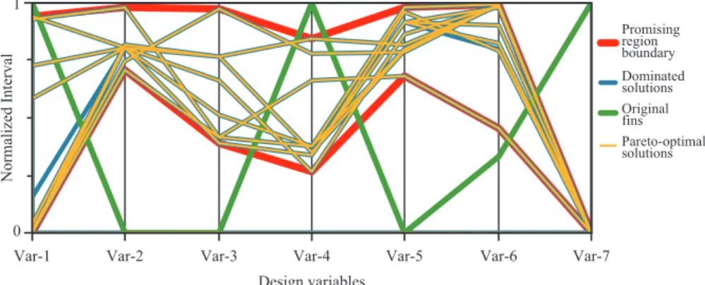
The optimization is a trial process. It consists of choosing the preliminary intervals for the design variables. The output interface for optimization results uses a method for analyzing multivariate data, which is called parallel coordinates. This
method consists of parallel lines, vertical and equally spaced, where each line corresponds to a design variable and the maximum and minimum values of each variable are usually scaled to the upper and lower boundaries on their respective OLQHV*ULQVWHLQHWDO8VLQJWKLVDSSURDFKRQHYHUL¿HV graphically, whether the promising region of the search space is reaching the lower and upper bounds or not. Then, if it does, it suggests that the bounds should be extended. Otherwise, it may suggest that the bounds should be more restrictive. Furthermore, the analyses of the optimization results may expose unfeasible conditions that were not considered before in the optimization problem. Thus, the optimization is also a learning process on the self-optimization problem.
CASE STUDY
This section presents the case study of the VS-40 by using the MDO-SONDA. Firstly, the elements of the optimization SUREOHPZLOOEHGH¿QHG7KHQWKHVHWWLQJVRIWKHPXOWLREMHFWLYH nongenerational genetic algorithm will be presented, and WKHVROXWLRQVWRLPSURYHWKH96¿QVZLOOEHFRPPHQWHG Finally, a mission analysis considering a hypothetical payload mass to microgravity experiment will be presented on the point of view of the trajectory discipline to evaluate the gain REWDLQHGZLWKWKHLPSURYHG¿QVLQFRPSDULVRQZLWKWKH96 ZLWKLWVRULJLQDO¿QVWDNLQJLQWRDFFRXQWWKHLQÀXHQFHRIZLQG DQGGLVSHUVLRQIDFWRUVRIWKH96RQLWVÀLJKW
Design problem statement
7KHGHVLJQLVVXHPD\EHGH¿QHGDVIROORZV*LYHQWKH original design of the VS-40 with a payload of 240 kg, and assuming that this mass is the minimum acceptable for this URFNHWWKHJRDOLVWR¿QGDQLPSURYHGGHVLJQIRULWVWDLO¿QV To achieve such a goal, two design objectives were pursued: PLQLPL]DWLRQ RI WKH GUDJ IRUFH FDXVHG E\ WKH URFNHW ¿QV and maximization of the shortest interval between critical ÀLJKWHYHQWVZKLFKDUHWUDQVRQLFVSHHGPD[LPXPG\QDPLF pressure, minimum static margin, and pitch-roll crossing.
G\QDPLFSUHVVXUH7KHLUUHVSRQVHVDUHVLJQL¿FDQWO\UHODWHGWRWKH rocket propulsion. The static margin is the position of the center of pressure, where the aerodynamic forces act, minus the position of the center of gravity, both measured with respect to the nose tip as referential and positive in the direction of the rocket tail. If the static margin is negative, that is, the center of pressure is ahead of the center of gravity, the rocket is aerodynamically unstable. If it is positive but too small, it increases the rocket oscillations, which can affect the rocket performance. The pitch-roll crossing, that is, the crossing between the pitch and the pitch-roll rates, can lead to a physical phenomenon called roll resonance followed by the roll lock-in, where the roll rate deviates from its GHVLUHGSDWK&RUQHOLVVHHWDO, 1979). These two latter critical ÀLJKWHYHQWVDUHVLJQL¿FDQWO\DIIHFWHGE\WKH¿QVRIWKHURFNHW
Before proceeding with the comments on the solutions to LPSURYHWKH96¿QVDQXQREYLRXVTXHVWLRQZDVDQVZHUHG ZKHQDWWHPSWLQJWRPLQLPL]HWKHGUDJGXHWR¿QVGRHVWKH second objective suffer as a result? It is also demonstrated that the MDO methodology can be used to investigate whether design objectives are competing or not, leading to a more comprehensive understanding of the system’s trade-offs.
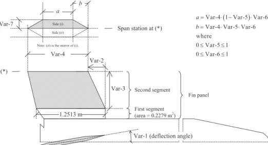
Figure 3 describes the design variables. The VS-40 is a ERG\WDLO URFNHW FRQ¿JXUDWLRQ ZLWK IRXU LGHQWLFDO WDLO ¿QV DUUDQJHGLQDFUXFLIRUPJHRPHWU\,WV¿QVKDYHKH[DJRQDO airfoil geometry and two segments. In this case study, only the second segment was subjected to optimization (Fig. 3). Still, the variation of mass and inertia properties related to the shape FKDQJHRIWKH¿QVZDVQHJOHFWHG
7KHLQWHUYDOVRIVKDSHYDULDWLRQRIWKH¿QVDUHHVWDEOLVKHG LQ7DEOHZKLFKGH¿QHVWKHFRQWLQXRXVGHVLJQVHDUFKVSDFH for optimization.
The optimization was subjected to the following side FRQVWUDLQWVUROOUDWH+]DQGVWDWLFPDUJLQFDOLEHUV Such constraints are necessary because excessive roll rate affects the structure, and too small static margin increases oscillations. Both situations can affect rocket performance.
Optimization settings and results
Table 2 presents the settings of the multiobjective nongenerational genetic algorithm used in MDO-SONDA. It also shows that the neighborhood radius and the graduation IDFWRUDUHSDUDPHWHUVRIWKH¿WQHVVIXQFWLRQZKLFKUHJXODWH the distribution of solutions along the Pareto front (Borges and Barbosa, 2000).
Despite the small number of design variables, this case study showed that computational cost could become an issue. A single simulation involving interactions between aerodynamics and trajectory calculations takes 12 seconds LQ D *+] 'XDO &RUH 6LQFH HYDOXDWLRQV RI WKH objective function were required for seven design variables, the optimization took four hours.
Var-4 1 Var-5 Var-6
Var-4 Var-5 Var-6 where
0 Var-5 1 0 Var-6 1 a
b
d d
d d
(*)
Var-3
Var-1 (deflection angle) Var-4
b a
Span station at (*)
Var-2 Var-7 Side (i)
Side (ii)
Note: (ii) is the mirror of (i).
First segment
(area = 0.2279 m2
) Second segment
1.2513 m
Fin panel
)LJXUH 'HVLJQYDULDEOHVRIWKHWDLO¿QDLUIRLODQGJHRPHWU\
Table 1. Bounds of the design variables.
Design variable Nominal /RZHUERXQG Upper bound
1 (degrees) 0.6 0.42 0.6
2 (m) 0 0 2.4843
3 (m) 0.7095 0.7095 0.9095
4 (m) 1.2513 1 1.2513
5 0.348038 0.348038 0.417646
6 0.799168 0.719 0.959002
We have found a Pareto front, demonstrating that the
PLQLPL]DWLRQRIWKHGUDJGXHWR¿QVDQGWKHPD[LPL]DWLRQ RI WKH VKRUWHVW LQWHUYDO EHWZHHQ FULWLFDO ÀLJKW HYHQWV DUH
competing objectives (Fig. 4).
,WVHHPVWKDWWKH¿WQHVVIXQFWLRQDVSURSRVHGE\%RUJHV
and Barbosa (2000), gave well-distributed points along the Pareto front (Fig. 4). However, despite the fact that population
VL]HZDV¿[HGDW7DEOH)LJRQO\SUHVHQWVDVHWRI
points. Indeed, in some of these points, there is more than one solution with slight differences between them.
Optimization results seem to be coherent. The interval between the transonic speed and the maximum dynamic
SUHVVXUHHYHQWVLVVHFRQGVQRPDWWHUZKDW¿QVDUHXVHG
The optimization could not lead to solutions that exceed such
LQWHUYDO)LJ$OVRWKHGUDJGXHWRWKHURFNHW¿QVFDQEH
reduced up to 29% without increasing the chances of adverse effects that could lead to unstable behaviors (Fig. 4). There are some chances that adverse effects increase when two or more
FULWLFDOÀLJKWHYHQWVRFFXUDWWKHVDPHLQVWDQW)LJXUHVKRZV
on [-axis the total drag minus its value without computing the
¿QVLQWKHGUDJFRHI¿FLHQWFDOFXODWLRQZKLFKLVN1
Thus, in terms of the total drag, the reduction was up to 5%. Regarding the parallel coordinates graph, the promising area of the search space has reached the limits of almost the totality of the design variables (Fig. 5).
In Fig. 5, regarding the line of Var-7, which is related to the
WKLFNQHVVRIWKH¿QVWKHUHVXOWVVXJJHVWWKDWWKHORZHUERXQG KDVWREHUHGXFHG&HUWDLQO\WKHERXQGVKDYHWREHNHSWZKHQ
they also want to avoid unfeasible solutions. Therefore, the lower bound of Var-7 is kept, assuming that its reduction can lead to structural issues.
Table 3 presents a Pareto-optimal solution associated with each point in Fig. 4. It is worth noting, based on Var-3 and Var-4 values in Table 3 and the chord at the base of the
VHFRQGVHJPHQWRIWKH¿QSDQHODQGWKHDUHDRIWKH¿UVWRQH Nose tip
Fin profile
-8 -7.5 -7 -6.5 -6 -5.5 -5 -4.5
0 1 2 3 4 5 6 7 8 9
Drag force caused by fins (kN)
S
h
o
rt
es
t i
n
te
rv
al
b
et
w
ee
n
c
ri
ti
ca
l f
li
g
h
t e
v
en
ts
(
s)
1 2 3 4 5 6 7 8 9 10 11
Original fins Pareto-optimal
solutions
Figure 4. Optimization results.
7DEOH'LPHQVLRQVRI¿QVIRUWKH96
Solution* Variable 1 (m) Variable 2 (m) Variable 3 (m) Variable 4 (m) a (m) b (m) Variable 7 (m) Original 0.600 0.000 0.710 1.251 0.652 0.348 0.0168
1 0.587 2.429 0.793 1.167 0.584 0.382 0.0117
2 0.589 1.995 0.787 1.084 0.608 0.426 0.0118
3 0.550 1.995 0.787 1.084 0.597 0.418 0.0118
4 0.526 1.995 0.787 1.084 0.584 0.409 0.0118
5 0.427 1.995 0.787 1.084 0.577 0.409 0.0118
6 0.420 1.766 0.793 1.095 0.610 0.440 0.0117
7 0.420 1.995 0.812 1.095 0.626 0.423 0.0117
8 0.420 1.995 0.842 1.066 0.603 0.416 0.0118
9 0.421 1.995 0.862 1.089 0.622 0.421 0.0118
10 0.420 2.029 0.862 1.212 0.690 0.470 0.0117
11 0.422 1.855 0.905 1.196 0.684 0.461 0.0118
*solutions are ordered as in Fig. 4. Table 2. Optimization algorithm settings.
Parameter Value
Size of the population 20
Number of generations 600
Neighborhood radius 2
*UDGXDWLRQIDFWRU 0.5
&RHI¿FLHQWRIPXWDWLRQ 1.4
/RZHUERXQGRIPXWDWLRQ 1
Upper bound of mutation 6
showed in Fig. 3, the Pareto-optimal solutions have from 2.8 to 19.6% more surface than the original panel. Surface area often has more impact than geometry, increasing the drag, despite any attempts to reduce it by choosing an adequate geometry. However, the extended surface area of the Pareto-optimal solutions does not seem to cause any disadvantage in
FRPSDULVRQZLWKWKHRULJLQDO¿QV
)LJXUHLVHYLGHQFHWKDWWKHRULJLQDO¿QVDUHQRWDGHTXDWH 7KHRULJLQDO¿QVRIWKH96KDYHUHFWDQJXODUSDQHOV)LJE $PRQJWKHSDQHOJHRPHWULHVIRU¿QVWKHUHFWDQJXODULVWKH
one that provides more drag in supersonic speed, based on equal surface area and span between the geometries (Fleeman,
'HVSLWHWKHUHGXFHGVXUIDFHDUHDRIWKHRULJLQDO¿QVLW
causes more drag than the Pareto-optimal solution number 11, which has the largest surface area.
Among the Pareto-optimal solutions, the drag increases as
WKHVXUIDFHDUHDLQFUHDVHVGHPRQVWUDWLQJWKHVWHDG\LQÀXHQFH
of the surface area (Fig. 6). However, the solution number 1 is an outlier, since it causes less drag than solutions from 2 to 7 but it has an area slightly extended with similar geometry (Fig. 4). Solutions are ordered as in Fig. 4.
Despite the fact that solutions providing the shortest
LQWHUYDO EHWZHHQ FULWLFDO ÀLJKW HYHQWV JUHDWHU WKDQ WZR
seconds are those safer than the solution number 1, for
PLVVLRQDQDO\VLVWKHLPSURYHG¿QVZHUHVHOHFWHGVLQFHLWLV
the Pareto-optimal solution that causes the largest reduction of the drag, increasing the rocket’s performance.
Mission analysis
The proposed mission to be analyzed is characterized by a hypothetical payload of 240 kg, which is carried by the VS-40 to be exposed to microgravity environment. If one suppose the mission is scheduled for December, corresponding to the
WUDQVLWLRQEHWZHHQWKHGU\DQGUDLQ\SHULRGVLQ&/$&DVWUR
and Fisch, 2007), when wind surface reduces gradually with
WKHRFFXUUHQFHRIUDLQWKHRSHUDWLRQZLOOEHEHQH¿WHG7KH
goal is to evaluate what is the gain in the performance of the
96ZLWKWKHLPSURYHG¿QVLQFRPSDULVRQZLWKLWVRULJLQDO
ones considering this hypothetical mission.
The maximum expected gain can be estimated without performing any optimization. The trajectory simulation
ZLWKRXWFRPSXWLQJWKH¿QVLQWKHGUDJFRHI¿FLHQWFDOFXODWLRQ
provides an expected gain of 2.9% (Fig. 7). Despite the small
LQÀXHQFH RI WKH ¿QV RQ WKH SHUIRUPDQFH RI WKH URFNHW LQ PLFURJUDYLW\DVUHÀHFWHGE\WKHVPDOOH[SHFWHGJDLQLWZDV
seen that the conditions of a mission analysis can affect the
JDLQGXHWRLPSURYHPHQWRIWKHURFNHW¿QV
,JQRULQJ WKH LQÀXHQFH RI WKH ZLQG DQG RI GLVSHUVLRQ IDFWRUVRIWKH96RQLWVÀLJKWDWRWDOGUDJUHGXFWLRQRI XVLQJWKHLPSURYHG¿QVFDXVHVDQHODSVHGÀLJKWWLPH
gain in microgravity of 1.6% (Fig. 7). However, since the VS-40 is an unguided rocket, wind effects and dispersion factors should be considered. The mission analysis consists of taking into account these factors in the evaluation of the
96FRQ¿JXUDWLRQVRQHZLWKWKHLPSURYHG¿QVDQGDQRWKHU
{2,3,4,5} Original solution
6 7
9
11 10
8
1
1.1 1.15 1.2 1.25 1.3 1.35 5
5.5 6 6.5 7 7.5 8
Area of the fin panel (m2)
Magnitude of the drag due to fins (kN)
)LJXUH'UDJGXHWR¿QVYHUVXV¿QSDQHODUHD
Design variables
Var-7 Var-6
Var-5 Var-4
Var-3 Var-2
Var-1
N
o
rm
al
iz
ed
I
n
te
rv
al
1
0
Promising region boundary Dominated solutions Original fins Pareto-optimal solutions
ZLWKWKHRULJLQDO¿QV7KHODXQFKD]LPXWKDQGHOHYDWLRQWKDW SURYLGHWKHGHVLUDEOHSUREDELOLW\WRSURFHHGEULHÀ\ZLWKWKH PLVVLRQDUH¿UVWO\REWDLQHGE\FRQVLGHULQJWKHZLQGHIIHFW 7KHQ¿[LQJWKHDGHTXDWHODXQFKD]LPXWKDQGHOHYDWLRQIRU HDFK96 FRQ¿JXUDWLRQ WKH WKHRUHWLFDO GHYLDWLRQ RI WKH elapsed time in microgravity is estimated by considering the dispersion factors of the rocket. Finally, the gain in the SHUIRUPDQFHRIWKH96ZLWKWKHLPSURYHG¿QVLVHVWLPDWHG based on the average value of the elapsed time in microgravity, LQFRPSDULVRQZLWKLWVRULJLQDOFRQ¿JXUDWLRQ
$ ODUJH SHUFHQWDJH RI WKH WRWDO ZLQG LQÀXHQFH RQ WKH URFNHWRFFXUVYHU\HDUO\LQÀLJKW'XULQJDQRSHUDWLRQLQWKH Brazilian territory, to compensate for the wind effect, it is necessary to adjust the launch azimuth and elevation based on wind data, which are collected few moments before liftoff. Two types of wind sensing devices are provided, rawinsondes to high altitudes and anemometer measurements RIZLQGVXUIDFHSUR¿OH7KHSURFHGXUHWRPDNHWKHODXQFK azimuth and elevation adjustments for sounding rockets, still adopted by the Brazilian launch centers, is based on Hennigh (1964). It consists of determining, for a range of launch elevations, the wind weighting as a function of the altitude, and the splashdown displacements caused by a unit range- and cross-wind, respectively. Such displacements are determined by considering the wind up to an upper limit of the effective atmosphere. The range-wind azimuth is given in the direction of the rocket launch tower, while WKHFURVVZLQGLVQRUPDOWRLW7KHQJLYHQDZLQGSUR¿OHDV input, the procedure consists of evaluating the ballistic wind, combining data provided by the wind sensing devices with
the wind weighting function, which had been previously calculated. The ballistic wind is hypothetical and constant in GLUHFWLRQDQGPDJQLWXGHIURPWKHJURXQGOHYHOWRDGH¿QHG upper limit of the effective atmosphere. In practice, the upper limit of the effective atmosphere is roughly 25 km (Hennigh, 1964). Finally, considering the ballistic wind, the splashdown displacement caused by a unit wind, and the assumption that the response of the rocket is linear with the wind velocity, the launch azimuth and elevation are adjusted. However, due to stochastic behavior of the wind, dispersion factors of the rocket, structural issues, geographical constraints, and rocket assumption of the linear response to make the adjustments,
WKHIROORZLQJFRQVWUDLQWVVKRXOGEHFRQVLGHUHGEl
A
$]A_El&-ElR_DQG_$]A-$]R_ZKHUHElA
and $]A are, respectively, the adjusted elevation and azimuth; and, El
R and $]R are, respectively, the reference elevation and
azimuth.
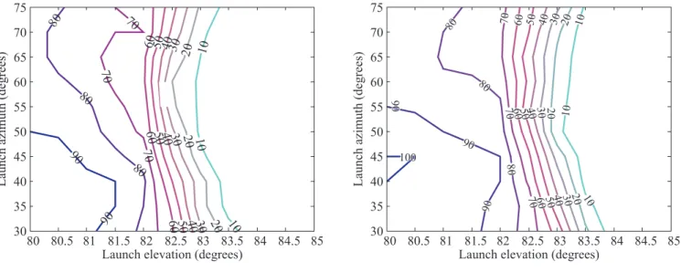
8VLQJVDPSOHVRIZLQGSUR¿OHVFROOHFWHGDW&/$LQ December 2008, obtained with sensors, we have estimated the probability of not violating such constraints for a range of launch azimuth and elevation values, given to one attempt of launch (Fig. 8).
Suppose the hypothetical mission cannot exceed two attempts of launch, given that the probability for one attempt (P) can be expressed by Eq. 4:
p 1 1 Pn n
1
= -^ - h (4)
where, P
n is the probability, between 0 and 1, for n attempts
of launch.
,QRUGHUWRQRWH[FHHGWKHOLPLWRIDWWHPSWV¿[LQJP
n at
0.98, for instance, the probability of not violating constraints of launch azimuth and elevation can be at least 0.9 (90%). As the elapsed time in microgravity increases with the launch elevation (Fig. 7), let us select the maximum launch HOHYDWLRQIRUHDFK96FRQ¿JXUDWLRQDVVRFLDWHGZLWK of nonviolation of the constraints. Based on Fig. 8, the VS-40 ZLWK LPSURYHG ¿QV FDQ EH ODXQFKHG DW DQG ZLWK WKH RULJLQDO¿QV7KHVHDUHWKHPD[LPXPODXQFKHOHYDWLRQV 7KHODXQFKD]LPXWKFDQEH¿[HGDWIRUERWKFRQ¿JXUDWLRQV
The theoretical deviation of the elapsed time in microgravity LVGHWHUPLQHGE\XVLQJ0RQWH&DUOR¶VPHWKRGZKLFKFRQVLVWV of varying the dispersion factors, and computing their results on the trajectory of the rocket, assuming a normal distribution RQWKHLUYDULDWLRQLQWHUYDOZKLFKLVGH¿QHGE\WKHLUUHVSHFWLYH error. The aerodynamic coefficients are, for instance,
80 80.5 81 81.5 82 82.5 83 83.5 84 84.5 85
880 900 920 940 960 980 1000 1020
Launch elevation (degrees)
E
la
p
se
d
f
li
g
h
t t
im
e i
n
m
ic
ro
g
ra
v
it
y
(
s)
The VS-40 with its original fins The VS-40 with improved fins The VS-40 without computing fins drag
Gain of 1.6% Gain of 2.9%
dispersion factors to be considered. Studies that evaluate the accuracy of the missile datcom compared to experimental wind tunnel data shows that the results for aerodynamic drag are predicted by missile datcom with an error, whose magnitude is less than 20% for a variety of rocket geometries (Sooy and Schmidt, 2005). At transonic speeds, where boundary layer shock interaction takes place, missile datcom does not have the capability to accurately represent such kind of interaction. Table 4 presents the dispersion factors that were assumed to calculate the deviation of the elapsed time in microgravity.
No predominant wind speed and direction have been considered in the calculation of the deviation of the elapsed time in microgravity. Table 5 presents the deviation of the elapsed time in microgravity.
&RQVLGHULQJWKHPD[LPXPODXQFKHOHYDWLRQVWKHHODSVHG WLPHJDLQLQPLFURJUDYLW\SURYLGHGE\WKHLPSURYHG¿QVFDQ increase from 1.6 to 2.9% (Table 5). As previously discussed, the expected gain does not seem to justify any attempt of FKDQJLQJWKH¿QVRIWKH96%HVLGHVWKHH[SHFWHGHUURULV DSSUR[LPDWHO\¿YHWLPHVWKHJDLQLQPLFURJUDYLW\7DEOH2Q the other hand, it was demonstrated that the factors associated with the mission analysis could affect the gain evaluation. It is expected that, by involving more subsystems and design GLVFLSOLQHVLQIXWXUHZRUNVVLJQL¿FDQWLPSURYHPHQWVLQWKH Brazilian sounding rockets can be demonstrated regarding different applications, besides their application in microgravity experiments.
FUTURE WORKS
In future works, at least four lines of development should be considered. First, new functionalities may be added to the MDO-SONDA. Interfaces might be created for graphical FRPSDULVRQVRIWKHDHURG\QDPLFFRHI¿FLHQWVEHWZHHQSKDVH FRQ¿JXUDWLRQV'YLVXDOL]DWLRQRIWKHURFNHWDQGFXVWRPL]HG plots of the trajectory parameters. The user should be able to customize the optimization problem and to set the interaction Table 5. Average value and error of the elapsed time in microgravity.
/DXQFKHOHYDWLRQ
(degrees)
Elapsed time in microgravity (s)
:LWKRULJLQDO¿QV :LWKLPSURYHG¿QV
81.5 922±138 939±134
82 932±138 949±129
Launch elevation (degrees)
L au n ch a zi m u th ( d eg re es )
80 80.5 81 81.5 82 82.5 83 83.5 84 84.5 85 30 35 40 45 50 55 60 65 70 75 10 10 10 20 20 20 30 30 30 40 40 40 50 50 50 60 60 60 70 70 70 80 80 80 90 90 10 10 10 20 20 20 30 30 30 40 40 40 50 50 50 60 60 60 70 70 70 80 80 80 90 90 90 100 10 10 10 20 20 20 30 30 30 40 40 40 50 50 50 60 60 60 70 70 70 80 80 80 90 90 90 100
Launch elevation (degrees)
L au n ch a zi m u th ( d eg re es )
80 80.5 81 81.5 82 82.5 83 83.5 84 84.5 85 30 35 40 45 50 55 60 65 70 75
(a) (b)
Figure 8. Probability of not violating constraints of launch azimuth and elevation adjustment to compensate for the wind effect (%), given to
RQHDWWHPSWRIODXQFKD96ZLWKLWVRULJLQDO¿QVE96ZLWKWKHLPSURYHG¿QV
Table 4. Dispersion factors error for each rocket stage.
Dispersion factor Error
First stage Second stage
/DXQFKHUHOHYDWLRQHUURUGHJUHHV ±0.5 –
/DXQFKHUD]LPXWKHUURUGHJUHHV ±3.0 –
Head and cross wind (m/s) ±2.0 –
Thrust variation (%) ±3.0 ±3.0
Thrust misalignment in pitch and yaw
(degrees) ±0.1 ±0.1
Aerodynamic drag (%) ±20.0 ±20.0
Weight variation (%) ±1.0 ±1.0
Fin misalignment (degrees) ±0.01 ±0.01
ZLWKDQHZKLJK¿GHOLW\H[HFXWDEOHFRGHE\XVLQJDQLQWHUIDFH LQVWHDG RI DGGLQJ WR RU UHSODFLQJ D VSHFL¿F VXEURXWLQH LQ
MDO-SONDA. This latter should be able to recalculate the mass and inertia properties of the rocket considering the change of the shape that is being optimized. Data-mining methods might be included in the future to assist the user on searching for trade-offs, when the number of design variables and objectives are such that the traditional methods of data visualization are not enough to make them explicit. Also, the MDO-SONDA should be compared with other codes.
6HFRQG PRUH KLJK¿GHOLW\ FRGHV PD\ EH OLQNHG WR
MDO-SONDA, involving more design disciplines. For instance, teamwork involving experts in propulsion and
VWUXFWXUH PLJKW SURYLGH UHVSHFWLYHO\ VSHFL¿F FRGHV WR
generate the thrust curve from the propellant variables and to estimate the structural resistance of the rocket against
DHURG\QDPLFORDGVGXULQJWKHÀLJKW)XUWKHUPRUHDQDQDO\VLV FDQEHSHUIRUPHGWRVWXG\WKHLQÀXHQFHRIWKHHUURURIWKH KLJK¿GHOLW\FRGHVRQWKHGHVLJQRSWLPL]DWLRQ
Third, the optimization mechanisms may be more
GLYHUVL¿HG DQG VRSKLVWLFDWHG 0HPHWLF DOJRULWKPV DUH WKH
combination of two or more metaheuristics, cooperating or competing with each other, and surrogate models might improve the overall performance of the optimization by reducing the number of objective function evaluations. Parallel computing might be used together with such approaches for large-scale optimization problems. The search for appropriate parameter values related to the optimization mechanisms are an issue for future works.
Finally, with respect to the last line of development to be seen in future, two or more subsystems may be redesigned, simultaneously, to improve the rocket, for instance, two or more
VHWVRI¿QV¿QVDQGQRVHIDULQJDQGVRRQ6HQVLWLYLW\DQDO\VLV
can be executed to investigate the impact of any variations of the design variables on the its objectives. In addition, two or more missions with respect to the same rocket may be simultaneously considered at the same optimization process.
CONCLUSIONS
In this paper, a MDO application in the context of Brazilian sounding rockets was demonstrated. As case study, the shape
RSWLPL]DWLRQRI¿QVRIWKH96ZDVSUHVHQWHGUHJDUGLQJLWV
next launches at the Brazilian territory to perform microgravity experiments. This paper began by introducing the concepts of sounding rockets and the microgravity environment, which was followed by presenting facts about the VS-40, and explaining
why it should be revised. Before commenting the results of the optimization, the main aspects of the MDO-SONDA were depicted. It was found that the minimization of the drag due
WR¿QVDQGWKHPD[LPL]DWLRQRIWKHVKRUWHVWLQWHUYDOEHWZHHQ FULWLFDOÀLJKWHYHQWVDUHFRPSHWLQJREMHFWLYHVOHDGLQJWRDPRUH
comprehensive understanding of the VS-40 trade-offs. The drag
GXHWRWKHURFNHW¿QVFRXOGEHUHGXFHGXSWRDQGZLWKDQ LQWHUYDORIDWOHDVWRQHVHFRQGEHWZHHQFULWLFDOÀLJKWHYHQWV
in order to avoid adverse effects that could lead to unstable behaviors. However, in terms of the total drag, the reduction was
XSWRFDXVLQJDQHODSVHGÀLJKWWLPHJDLQLQPLFURJUDYLW\RI ZLWKRXWLJQRULQJWKHLQÀXHQFHRIWKHZLQGDQGWKHGLVSHUVLRQ
factors of the rocket. Despite the small gain, it was demonstrated that the factors associated with the mission analysis could affect the gain evaluation. Finally, four lines of development for future works were suggested: the addition of new functionalities to MDO-SONDA; the participation of more design disciplines,
FRQWULEXWLQJZLWKWKHLUKLJK¿GHOLW\FRGHVWKHLPSURYHPHQWRI
the optimization mechanisms, adding sophisticated methods, such as surrogate models; and the simultaneous optimization of two or more subsystems of the rocket.
REFERENCES
%DUERVD$1DQG*XLPDUmHV/1)³,QYHVWLJDWLQJ WKH(I¿FLHQF\RIWKH6XUURJDWHV%DVHGRQ1HXUDO1HWZRUNV
in Assisting Multi-objective Optimization of Test-problems
3HUIRUPHG E\ D 1RQJHQHUDWLRQDO *HQHWLF $OJRULWKP´ ,Q 3URFHHGLQJV RI WKH UG ,QWHUQDWLRQDO &RQIHUHQFH RQ
Engineering Optimization, Rio de Janeiro.
%ODNH:%³0LVVLOH'DWFRP8VHU¶V0DQXDO±)RUWUDQ 5HYLVLRQ´:ULJKW3DWWHUVRQ$LU)RUFH%DVH2KLR86$
%RUJHV&&+DQG%DUERVD+-&³$QRQJHQHUDWLRQDO JHQHWLF DOJRULWKP IRU PXOWLREMHFWLYH RSWLPL]DWLRQ´ LQ SURFHHGLQJV RI WKH &RQJUHVV RQ (YROXWLRQDU\ &RPSXWDWLRQ/D-ROODSS
&DVWUR/&DQG)LVFK*³(VWXGRGR0HLR$PELHQWH $WPRVIpULFR 3URGX]LGR SDUD $WHQGHU R /DQoDPHQWR GR 96%9´,QVWLWXWRGH$HURQiXWLFDH(VSDoR6mR-RVp GRV&DPSRV57)S
&RUQHOLVVH -:HW Dl ³5RFNHW 3URSXOVLRQ DQG
6SDFHÀLJKW'\QDPLFV´3LWPDQ/RQGRQS
)OHHPDQ(/³7DFWLFDO0LVVLOH'HVLJQ´QGHGLWLRQ
AIAA, Reston, 468 p.
)ORXGDV&$DQG3DUGDORV30³(QF\FORSHGLDRI 2SWLPL]DWLRQ´QGHGLWLRQ6SULQJHU1HZ<RUNS
*DUFLD$HWDl³96%VRXQGLQJURFNHWKLVWRU\RI
ÀLJKWSHUIRUPDQFH´-RXUQDORI$HURVSDFH7HFKQRORJ\DQG
Management, Vol. 3, No. 3, pp. 325-330.
*HUPDQ\¶V 1DWLRQDO 5HVHDUFK &HQWHU IRU$HURQDXWLFV DQG 6SDFH'/5³([SHULPHQWVRQ6+()(;,,VXFFHVVIXO´ '/53RUWDOZHEVLWH5HWULHYHGLQ-XO\IURPKWWS
www.dlr.de/dlr/en/desktopdefault.aspx/tabid-10081/151_ read-4100/.
*RPHV50³7UDMHFWRU\FDOFXODWLRQXVLQJWKH526, SURJUDP±1RPLQDO7UDMHFWRU\DQDO\VLV´7HFKQLFDO5HSRUW
ASE-RT-010-2004, Institute of Aeronautics and Space, Brazil.
*ULQVWHLQ*HWDl³+LJK'LPHQVLRQDO9LVXDOL]DWLRQV´
In: Proceedings of the Visual Data Mining Workshop, San Francisco, USA.
+HQQLJK .( ³)LHOG :LQG :HLJKWLQJ DQG ,PSDFW 3UHGLFWLRQ IRU 8QJXLGHG 5RFNHWV´ 1DWLRQDO $HURQDXWLFV
and Space Administration (NASA), Washington, NASA TN D-2142, 22 p.
,QVWLWXWRGH$HURQiXWLFDH(VSDoR,$(³2)RJXHWHGH VRQGDJHP96´6mR-GRV&DPSRV%UD]LO5HWULHYHGLQ 2FWREHUIURPZZZLDHFWDEU"DFWLRQ YV
/D1HYH$DQG&RUUrD-U)$³6$5$([SHULPHQW
Module: An Interdisciplinary Project through Partnership
ZLWKWKH,QVWLWXWHRI$HURQDXWLFVDQG6SDFH´,Q3URFHHGLQJV RIWKH,QWHUQDWLRQDO&RQIHUHQFHRQ(QJLQHHULQJ(GXFDWLRQ
Oslo, Norway.
Montenbruck, O. HWDl³*367UDFNLQJRI6RXQGLQJ
5RFNHWV±$(XURSHDQ3HUVSHFWLYH´,Q3URFHHGLQJVRIWKH
1st ESA Workshop on Satellite Navigation User Equipment Technologies, Noordwijk, Holland.
0RUDHV-U3DQG3LOFKRZVNL+8³3ODWDIRUPD2UELWDO SDUD([SHULPHQWDomRHP$PELHQWHGH0LFUR*UDYLGDGH´,Q 3URFHHGLQJVRIWKH;,9&RQJUHVVR%UDVLOHLURGH(QJHQKDULD
Mecânica, Bauru-SP, Brazil, Vol. 1, 9 p.
3HUHLUD$/DQG0RUDHV-U3³(QVDLRV$HURGLQkPLFRV HP9{RGR)RJXHWH6XERUELWDO96´LQSURFHHGLQJVRIWKH ;9 &RQJUHVVR 1DFLRQDO GH (QJHQKDULD 0HFkQLFD 1DWDO
Brazil. Retrieved in July 6, 2012, from http://pintassilgo2.
LSHQEUELEOLRWHFDFGFRQHP,&SGI
5HGG\.3-³+\SHUVRQLF)OLJKWDQG*URXQG7HVWLQJ $FWLYLWLHVLQ,QGLD´,Q3URFHHGLQJVRIWKHWK$XVWUDODVLDQ )OXLG0HFKDQLFV&RQIHUHQFH*ROG&RDVW$XVWUDOLD
5LEHLUR 76 ³9HtFXORV /DQoDGRUHV GH 6DWpOLWHV ± &HQiULR$WXDOH)XWXUR´3DUFHULDV(VWUDWpJLFDV1RSS
235-247.
5RZHOO/)DQG.RUWH--³/DXQFK9HKLFOH'HVLJQ
and Optimization Methods and Priority for the Advanced
(QJLQHHULQJ (QYLURQPHQW´ 1DWLRQDO $HURQDXWLFV DQG
Space Administration (NASA), Hampton, Virginia, NASA/ TM-2003-212654, 29 p.
6RR\7-DQG6FKPLGW5=³$HURG\QDPLF3UHGLFWLRQV &RPSDULVRQVDQG9DOLGDWLRQV8VLQJ0LVVLOH'$7&20 DQG$HURSUHGLFWLRQ$3´-RXUQDORI6SDFHFUDIWDQG
Rockets, Vol. 42, No. 2, pp. 257-265.
9DOHQ]XHOD5HQGyQ 0 DQG 8UHVWL&KDUUH ( ³$ QRQJHQHUDWLRQDO *HQHWLF $OJRULWKP IRU PXOWLREMHFWLYH RSWLPL]DWLRQ´ ,Q 3URFHHGLQJV RI WKH WK ,QWHUDQWLRQDO &RQIHUHQFHRQ*HQHWLF$OJRULWKPV6DR0DWHRSS
Weihs, H. HWDlD³7KH6KDUS(GJH)OLJKW([SHULPHQW
6+()(;,,D0LVVLRQ2YHUYLHZDQG6WDWXV´,Q3URFHHGLQJV
of the AIAA 15th Space Planes and Hypersonic Systems and
7HFKQRORJLHV&RQIHUHQFH2KLR86$
Weihs, H. HW Dl E ³.H\ ([SHULPHQWV ZLWKLQ WKH
6KHIH[,,0LVVLRQ´,Q3URFHHGLQJVRIWKHWK,QWHUQDWLRQDO $VWURQDXWLFDO&RQJUHVV*ODVJRZ6FRWODQG