Evaluation of indirect methods of digitization
of cephalometric radiographs in comparison
with the direct digital method
Cleomar Donizeth Rodrigues*, Márcia Maria Fonseca da Silveira**, Orivaldo Tavano***, Ronaldo Henrique Shibuya****, Giovanni Modesto*****, Carlos Estrela******
Objective:To evaluate the indirect digitization method of cephalometric radiographs in com-parison with the direct digital method. Methods: The sample was composed of ten cephalo-metric radiographs acquired by Orthopantomograph OP100/Orthocef OC100 (GE – Instru-mentarium), digital direct. In the Adobe™ Photoshop program, five cephalometric landmarks were set in the images and the impression in transparencies was made. The indirect digitization of the images was performed through the Sony™ DSC-W5 and Canon™ Rebel XT/EOS 350D digital photographic cameras—fixed in a copy stand, at the distances of 25 cm and 60 cm—and through the Hewlett Packard™Scan Jet 4C scanner. The direct digital images and the indirect ones were inserted and gauged in the Radiocef Studio (Radiomemory™, Brazil) software and the center of the previously marked landmarks was set. The cephalometric com-puterized analysis generated three angular measurements and four linear ones which were submitted to statistical analysis. Results: The images from the scanner demonstrated small statistically significant alterations, without clinical significance. When digitizing the radiographs at 60 cm, both cameras caused distortions which were statistically significant, but clinically ac-ceptable. At 25 cm, the cameras caused the largest distortions, being more expressive and with clinical significance in the images of Canon™ Rebel XT. Conclusions: The Hewlett Packard™ Scan Jet 4C scanner with transparency reader and the Sony™ DSC-W5 and Canon™ Rebel XT/EOS cameras operating at 60 cm were shown appropriate for the digitization of cephalo-metric radiographs. In 25 cm, the digital cameras caused distortions in the image which altered the linear measurements with possibilities of jeopardizing the orthodontic diagnosis.
Abstract
Keywords: Digital dental radiography. Orthodontics. Radiographic image interpretation. Computer-assisted cephalometrics.
* MSc in Dental Radiology, São Leopoldo Mandic Dental Research Center, Campinas/SP, Brazil. Post-graduate student in Health Sciences, Federal University of Goiás, Goiânia, GO, Brazil. Professor of Radiology, Brazilian Dental Association, Brasília, DF, Brazil.
** PhD in Oral Diagnosis, University of São Paulo, Brazil. Professor of Oral Diagnosis, University of Pernambuco, Recife, PE, Brazil.
*** PhD in Oral Diagnosis, University of São Paulo, Brazil. Professor of Radiology, São Leopoldo Mandic Dental Research Center, Campinas/SP, Brazil. **** MSc in Dental Radiology, São Leopoldo Mandic Dental Research Center, Campinas/SP, Brazil.
***** Specialist in Orthodontics and Facial Orthopedics, Brazilian Dental Association, Uberlândia/MG, Brazil.
INTRODUCTION
The direct digital X-ray has become an alterna-tive to the conventional X-ray due to the possibility of image manipulation, radiation dose reduction to the patient, better filing and information access.1,2
However, in many radiological clinics this is not a reality yet and the traditional film continues to be the image receiver. In computerized cephalometry, the information of the radiographic image must be introduced in the software, through the direct ac-quisition or by the indirect digitization of the radio-graphs. The indirect digitization was initially made by plotting in digitizer tables3 and later by video
cameras.4 Since 1993 it was observed that the
con-ventional radiographic images could be converted into a digital sign by using a high resolution scanner,5
and then it became recommended by the manufac-turers of cephalometry softwares. It is very similar to a Xerox machine and is available in three types: laser, rotating drum and flatbed.6 They are all endowed
with light source in line shape that scans the image by measuring the amount of reflected or transmit-ted light in each dot. The captured light is turned into an electric sign, with the aid of photodetector groups which also form a line, and the electric sign is digitized and sent to the computer. The flatbed scanner was shown sensitive to the scanning arrange-ments, power state and image locations, while such inconsistencies were not observed in the rotating drum scanner (VXR-12),6 what can be explained
by its design. However, the space resolution, geo-metric distortion and CCD (charge coupled device) structure interference of this scanner require further studies.6 When comparing the manual
cephalom-etry to the computerized one, by using the VXR-12 scanner as a digitizer, there were statistically significant amplifications in both linear and angular measurements, although 21 out of the 27 presented differences smaller than 2 degrees or 2 mm, what is within of the norms of most of the cephalometric analyses and therefore without clinical significance.7
Another researchers scanned thirty lateral cepha-lograms in 300 dpi, and the findings demonstrated
that the use of computer software for cephalometric analysis carried out on scanned images does not in-crease the measurement error when compared with manual tracing.8 High quality image equipment are
very expensive and this is an unfavorable factor that added to the time consumption to digitize radio-graphs into a scanner has been motivating clinicians to use digital photographic cameras, with the aim of replacing the scanner. However, the literature in such field is scarce, leading to lack of standardization and consequent unreliability of the results.
The digitization systems based on cameras, un-like the scanning systems, present lower reproduc-ibility because they require position and zoom adjustment.6 The lens of the camera usually focus
the light into a plan behind it, and in conventional cameras such plan contains the photographic film. Nevertheless, in the digital cameras it is replaced by a sensor which captures luminous pulses and trans-forms them into electric pulses which are converted into digital image; in other words, the sensor gen-erates the pixels.9 Not only the size of the pixel is
important, but also the size of the sensor, because the larger the area to absorb light the better the final image. Most of the popular cameras use 1/1, 8-in or 2/3-in sensors.9 The sensor can be CCD (charge
coupled device) or CMOS (complementary metal oxide semiconductor). As the lenses of the cam-eras are not plane, the digitized images may pres-ent distortions in barrel or pincushion shapes.10 In
the former the images seem to be inflated, and take place where the focal distance is smaller, as for the latter there is a compression of the image in its own center and it is registered in larger focal distances. Such distortions are more visible in the images with perfectly straight lines, mainly when they are close to the edge,10 therefore also visualized in the
A
B C
linear measurements and to the demarcation of the cephalometric landmarks, which tend to be larger in the digital images than in the conventional ones; and that the space resolution of the digital image is lower than in the conventional X-ray.2 To digitize
ra-diographs with digital photographic cameras a light box is recommended with a high frequency fluores-cent lamp and intensity enough for the films to be clearer and sharpen for the sensor to accomplish the acquiring. The further the camera is from the light box using the zoom to frame the X-ray, the better it will be for the sharpness of the focus, the depth of the field and the homogeneity of the lighting.11
For radiographs presenting clear center and dark ex-tremities, a dark mask is used around it to compen-sate the automatic exposure which is focused in the center of the image.11 When testing an amateur
digi-tal camera to digitize images of forty bone trauma films and to transmit them through Telemedicine net to be assessed by specialists, it was observed that there was no significant difference in the diagnostic precision between the conventional film and digital image, as well as the quality of the image, which was classified as excellent.12 The direct digital radiograph
obtained by storage phosphor technique has already been recognized as reliable in computerized cepha-lometry, when compared to the manual cephalom-etry in conventional radiographic films.13,14
This work aimed to evaluate the reliability of using—in computerized cephalometric studies— the indirect digitization of lateral cephalometric radiograph by means of two models of digital pho-tographic cameras, as well as an flatbed scanner with a transparency reader, in comparison with direct digital radiograph obtained in CCD.
MATERIAL AND METHODS
Ten lateral cephalometric radiographs from the Orthopantomograph OP100/Orthocef OC100 (GE – Instrumentarium) digital direct unit were randomly selected; the files belonged to São Leo-poldo Mandic Post-graduations Center. In the Ado-be™ Photoshop program, using the Paintbrush tool,
five cephalometric landmarks were set: N = nasion, S = sella, Ar = articulare, Go = gonion and Me = menton. The radiographs were printed, in 100% size, in 3M™ transparencies with a HP™ Laser Jet 1320 printer and indirectly digitized by HP™ Scan Jet 4C scanner with transparency reader, in 75 dpi, and by the following digital photographic cameras: Sony™ DSC W5 (5.1 megapixels) and Canon™ Rebel XT/EOS 350D (8.0 megapixels, 55 mm lens). The cameras were fastened in a Incaf™copy standy (Fig 1), perpendicularly, 25 cm and 60 cm away from the printed radiographs, positioned with a Desetec™ millimeter ruler on a negatoscope (four Osram™ Dulux F 36W/21-840 fluorescent lamps) in an semi-dark room. The cameras operat-ed in the automatic mode, without flash and using optical zoom until the image filled out the entire camera visor. The distance and parallelism of the cameras and radiographs were verified with a Star-ret™ measure tape and a Tramontina™ level. All the direct and indirect digital images were inserted into the Radiocef Studio (Radiomemory™, Brazil) cephalometry software. For the calibration of the direct digital images, acquired in 350 dpi, the up-per and lower borders of the image were marked, previously measured in the Adobe Photoshop™ (16 cm). For the indirect digital images of the cam-eras the numbers zero and sixteen were marked in the photographed ruler; and the images of the
1. (S-N).Ar
2. (S-Ar).Go
3. (Ar-Go).Me
4. S-N
5. Go-Me
6. N-Me
7. S-Go N
S
Ar
Go
Me
scanner, in 75 dpi, were not gauged because this is the standard resolution of the software. An experi-enced radiologist, using the zoom tool of the soft-ware, marked the center of the landmarks, previ-ously located in the Photoshop. The cephalometric analysis, created by planes with distant landmarks distributed in the center and in the periphery of the image, generated four linear measurements and three angular ones (Fig 2). The effects of variables Camera and Distance were statistically assessed through the variance analysis with repeated mea-sures and the comparisons between mean pairs by Student t test for paired samples. The significance level of p < 0.05 was adopted for all tests.
FIGURE 2 - Cephalogram created for this research.
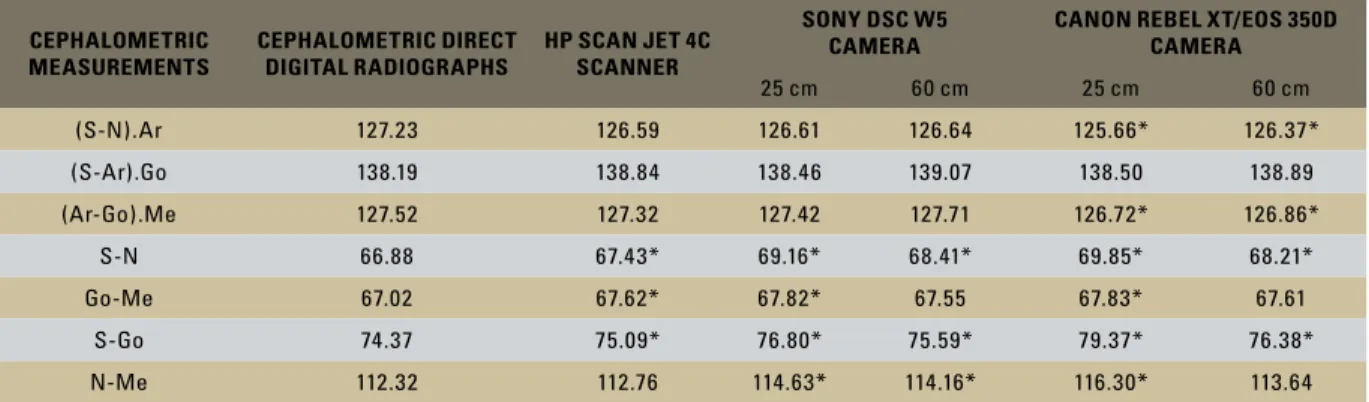
*Significant at the level of 5% in relation to the mean of the direct digital method.
TABLE 1 - Mean values of the measurements, obtained on the direct digital cephalometric X-ray in comparison with the images from the scanner and from the combinations of cameras and distances.
CEPHALOMETRIC MEASUREMENTS
CEPHALOMETRIC DIRECT DIGITAL RADIOGRAPHS
HP SCAN JET 4C SCANNER
SONY DSC W5 CAMERA
CANON REBEL XT/EOS 350D CAMERA
25 cm 60 cm 25 cm 60 cm
(S-N).Ar 127.23 126.59 126.61 126.64 125.66* 126.37*
(S-Ar).Go 138.19 138.84 138.46 139.07 138.50 138.89
(Ar-Go).Me 127.52 127.32 127.42 127.71 126.72* 126.86*
S-N 66.88 67.43* 69.16* 68.41* 69.85* 68.21*
Go-Me 67.02 67.62* 67.82* 67.55 67.83* 67.61
S-Go 74.37 75.09* 76.80* 75.59* 79.37* 76.38*
N-Me 112.32 112.76 114.63* 114.16* 116.30* 113.64
RESULTS
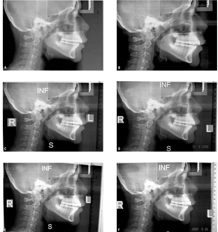
Table 1 shows the mean values obtained from the measurements performed in the direct digital radiographs as well as in the indirect ones from the scanner and from the combinations of cam-eras and distances. The mean values of the combi-nations marked with an asterisk showed statisti-cally significant differences at the level of 5% in relation to the correspondent mean obtained by the direct digital procedure. Figure 3 displays the distortions produced by the evaluated methods: In (A) direct digital image, without distortions; in (B) image digitized by the HP™ Scan Jet 4C scanner, without perceptible distortion in a vi-sual observation; In (C, D, E and F) the images of cameras, in both distances, with the presence of distortions in the borders. It can be observed that within the distance of 60 cm (C, D) the im-ages were less altered; while within 25 cm (E, F) there was larger distortion, mainly in the images digitized by Canon™Rebel XT (E).
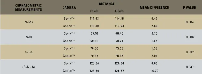
the linear ones S-Go and N-Me according to the distance (p <0.05). Table 3 shows the mean values of the measured variables, according to the cam-era type and distance. Table 4 demonstrates the influence of the camera type and distance on the measurements, confirming the existence of statis-tically significant alterations (p <5%) for all im-ages when the distance is changed. S-N horizontal line was the most affected (p = 0.006), followed by the vertical one N-Me (p = 0.004). The larger mean difference among the two distances was seen in Canon™ Rebel camera (2.99 mm) in the vertical measurement S-Go, which was located towards the center of the lens.
*Significant at the level of 5%.
** Significant interaction between camera and distance.
TABLE 2 - F test p-values for the variance analysis of the repeated mea-sures in order to study the effect of the camera and distance factors on the measurements.
CEPHALOMETRIC
MEASUREMENTS CAMERA DISTANCE
(S-N).Ar** 0.187 0.047*
(S-Ar).Go 0.693 0.101
(Ar-Go).Me 0.004* 0.129
S-N** 0.030* 0.052
Go-Me 0.762 0.474
S-Go** < 0.001* 0.032*
N-Me** 0.256 0.047*
TABLE 4 - Influence of the camera type and distance on the N-Me, S-N, S-Go and (S-N).Ar measurements. *Significant at the level of 5%.
TABLE 3 - Mean values of the distances measured according to the camera type and distance.
(S-N).Ar (S-Ar).Go (Ar-Go).Me S-N Go-Me S-Go N-Me
CAMERA
Sony™ 126.64 138.77 127.57* 68.78* 67.68 76.19* 114.39
Canon™ 126.01 138.69 126.79* 69.03* 67.72 77.88* 114.97
DISTANCE
25 cm 126.15* 138.48 127.01 69.50 67.82 78.09* 115.47*
60 cm 126.51* 138.98 127.28 68.31 67.58 75.98* 113.90*
CEPHALOMETRIC
MEASUREMENTS CAMERA
DISTANCE
MEAN DIFFERENCE P VALUE
25 cm 60 cm
N-Me
Sony™ 114.63 114.16 0.47
0.004
Canon™ 116.30 113.64 2.66
S-N
Sony™ 69.16 68.40 0.76
0.006
Canon™ 69.85 68.21 1.64
S-Go
Sony™ 76.80 75.59 1.39
0.032
Canon™ 79.37 76.38 2.99
(S-N).Ar
Sony™ 126.64 126.64 0.00
0.047
A
C
E
B
D
F
FIGURE 3 - A) Direct digital X-ray. B) Image digitized on the HP ScanJet 4C scanner. C, D) Images digitized at 60 cm by the Canon Rebel and Sony W5 cameras, respectively. E, F) Images digitized at 25 cm by the Canon Rebel and Sony W5 cameras, respectively.
DISCUSSION
The lateral cephalometric radiographs allow us to quantify facial and dental relationships,15
by the comparison of the cephalometric
in relation to the morphologic characteristics of an individual. Among the several auxiliary instru-ments used to enhance orthodontic diagnosis, the cephalometric analyses are indeed valuable. Nev-ertheless, they are subject to erroneous and mis-taken interpretations, in function of the necessary registrations to obtain them. In the computerized cephalometry, besides the mistakes committed in the conventional method, there is also the pos-sibility of two other problems: the identification of the cephalometric landmarks in function of the loss of quality of the images2,16 and mistakes
caused by calibration.2 To identify these was not
the aim of this study, which had just the inten-tion of assess the alterainten-tions in the measurements performed in the images digitized by the digital photographic cameras and by scanner, consider-ing that the latter is globally accepted, while the cameras are still little investigated. With the aim of not making location or demarcation mistakes, the cephalometric landmarks were previously marked in the direct digital images and confirmed in the cephalometry software on the images digi-tized with the scanner and the cameras.
Tradition imposes us to use angular and linear measurements for the evaluation of the structures of the craniofacial frame,17,18 however, individual
measures are insignificant if they are not correctly interpreted in a global context. In a general way, linear measurements are more reliable than an-gular ones, and the latter can be influenced by the former ones. For instance: an increased or re-duced length of the cranial base (S-N) may alter the (S-N).A, (S-N).B and (A-N).B angles,18 just
the same way that an increased inclination of S-N19 in relation to the Frankfurt plane decreases
the angular measurements (S-N).A, (S-N).B and (A-N).B, being able to bring about mistaken in-terpretations for the individual.
When comparing the image digitized by the HP™Scan Jet 4C scanner in 75 dpi to the direct digital X-ray (Table 1), it was observed that all angular and the linear measurement N-Me did
not suffer statistically significant alterations. Significant amplification was verified in the linear measurements S-N (0.82%, 0.55 mm), Go-Me (0.89%, 0.60 mm) and S-Go (0.9%, 0.72 mm), however, those are clinically accept-able because the differences for the measure-ments in the direct digital X-ray were lower than 1 mm and 1 degree—which are below the norm of the most used cephalometric analyses. Therefore, as other scanner types studied,6,8
we can also consider the flatbed scanner with transparency reader reliable for digitization of cephalometric radiographs. The differences be-tween the scanner and the direct digital X-ray can be explained because of the fact that the scanner is sensitive to the “scanning” arrange-ments, including the location and orientation of the image and power state.6 However, we
be-lieve that there may be a minimum difference in the distance between the two landmarks set in the digital image and the real distance be-tween them, informed to the “software” in the moment of the calibration of the images, being this hypothesis corroborated by authors who have claimed that the calibration of the digital image produces few but significant errors.2
The Canon™ camera showed statistically sig-nificant alterations in the angular measurements (S-N).Ar and (Ar-Go).Me, at distances of 25 cm and 60 cm (Table 1), however, all lower than 2 degrees. The largest difference was for (S-N). Ar (1.57 degrees at 25 cm and 0.86 degrees at 60 cm), which also meant no clinical signifi-cance. All the linear measurements of Canon™, at 25 and 60 cm, underwent statistically signifi-cant amplifications, except N-Me and Go-Me at 60 cm. At 60 cm, S-N and S-Go presented with statistically significant alterations, although considered clinically insignificant in agree-ment with the cephalometric analyses, because the highest difference was of 2 mm for S-Go. However, when digitized at 25 cm all linear measurements presented statistically significant alterations, being S-Go the most enlarged one (5 mm), followed by S-N (2.97 mm). S-Go is used to evaluate the subsequent vertical propor-tion of the face in comparison with the previous facial height (N-Me),20 while S-N evaluates the
length of the cranial base in relation to the man-dibular plane (true horizontal:Go-Me), in the description of facial patterns (long face versus short face), and in the description of the verti-cal growth (low and high angles). Therefore the alterations caused by Canon™ at 25 cm could cause mistaken interpretations and might con-sequently interfere in the diagnosis as well as in the individualized orthodontic treatment plan.
When photographing, the cameras were with the upper part turned to the lower board of the radiographs (Fig 1), pointing to the less amplified horizontal measurement (Go-Me), in both cam-eras at 25 and 60 cm. The most amplified in the Canon™ at 25 and 60 cm, and in Sony™ at 25 cm was the vertical S-Go, located in the center of the lens, while in Sony™ at 60 cm was the vertical N-Me, in the left periphery of the lens. This fact confirms that the form and the convexity of the lens cause different distortions in different parts of the images10 and that there are construction
differences between the lenses of both cameras, because they belong to different manufacturers.
Cameras can be useful to digitize cephalomet-ric radiographs, but, before its clinical use, it is rec-ommended to compare them to other well-known and reliable methods, observing the choice of the lens, lens-object distance, use of a copy stand, cor-rect positioning and image calibration.
CONCLUSION
1. Wenzel A. Inluence of computerized information technologies on image quality in dental radiographs. Tandlaegebladet. 1991 Sep;95(12):527-9.
2. Forsyth DB, Shaw WC, Richmond S, Roberts CT. Digital imaging of cephalometric radiographs. Part 2: image quality. Angle Orthod. 1996;66(1):43-50.
3. Faber RD, Burstone CJ, Solonche DJ. Computerized interactive orthodontic treatment planning. Am J Orthod. 1978 Jan;73(1):36-46.
4. Lowey MN. The development of a new method of cephalometric and study cast mensuration with a computer controlled, video image capture system; part I: video image capture system. Br J Orthod. 1993 Aug;20(3):203-14. 5. Brooks SL, Miles DA. Advances in diagnostic imaging in
dentistry. Dent Clin North Am. 1993 Jan;37(1):91-111. 6. Chen SK, Chiang TC. Digitizing of radiographs with a
roller-type CCD scanner. Oral Surg Oral Med Oral Pathol Oral Radiol Endod. 1997 Jun;83(6):719-24.
7. Chen YJ, Chen SK, Yao JC, Chang HF. The effects of differences in landmark identiication on the cephalometric measurements in the traditional versus digitized
cephalometry. Angle Orthod. 2004 Apr;74(2):155-61. 8. Sayinsu K, Isik F, Trakyali G, Arun T. An evaluation of
the errors in cephalometric measurements on scanned cephalometric images and conventional tracings. Eur J Orthod. 2007 Feb;29(1):105-8.
9. Nilce K, Gurevich GJ. How digital cameras work. HowStuffWorks. [cited 2004 Oct 6]. Available from: http:// eletronics.howstuffworks.com/digital-camera4.htm. 10. Bockaert V. The 123 of digital Imaging. USA: Asimex; 2003. 11. Whitehouse R, Moulding F. Latitude and noise comparisons
between digital cameras and radiographic ilm scanner. J Telemed Telecare. 2000;6 Suppl 1:S41-2.
REFERENCES
12. Krupinski E, Gonzales M, Gonzales C, Weinstein RS. Evaluation of a digital camera for acquiring radiographic images for telemedicine applications. Telemed J E Health. 2000 Fall;6(3):297-302.
13. Geelen W, Wenzel A, Gotfredsen E, Kruger M, Hansson LG. Reproducibility of cephalometric landmarks on conventional ilm, hardcopy, and monitor-displayed images obtained by the storage phosphor technique. Eur J Orthod. 1998 Jun;20(3):331-40.
14. Chen YJ, Chen SK, Huang HW, Yao CC, Chang HF. Reliability of landmark identiication in cephalometric radiography acquired by a storage phosphor imaging system. Dentomaxillofac Radiol. 2004 Sep;33(5):301-6.
15. Krogman W, Sassouni V. A syllabus in roentgenographic cephalometry. Philadelphia: Center for Research in Child Growth;1957.
16. Houston WJ, Maher RE, McElroy D, Sherriff M. Sources of error in measurements from cephalometric radiographs. Eur J Orthod. 1986 Aug;8(3):149-51.
17. Downs WB. Variations in facial relationships: their
signiicance in treatment and prognosis. Am J Orthod. 1948 Oct;34(10):812-40.
18. Steiner C. The use of cephalometrics as an aid to planning and assessing orthodontic treatment. Am J Orthod. 1960;46:721-35.
19. Moorrees C. Natural head position: the key to cephalometry. In: Jacobsen A. Radiographic cephalometry. Chicago: Quintessence; 1995. p. 175-84.
20. Horn A. Facial height index. Am J Orthod Dentofacial Orthop. 1992 Aug;102(2):180-6.
Contact address
Cleomar Donizeth Rodrigues
SMHN – Q. 02, bloco A, sala 208, Ed. de Clínicas CEP: 70.710-100 – Brasília / DF, Brazil
E-mail: [email protected]