Comparative study between manual
and digital cephalometric tracing using
Dolphin Imaging software with
lateral radiographs
Mariane Bastos Paixão*, Márcio Costa Sobral**, Carlos Jorge Vogel***, Telma Martins de Araujo****
Objective: The purpose of this study was to compare angular and linear cephalometric measurements obtained through manual and digital cephalometric tracings using Dolphin Imaging® 11.0 software with lateral cephalometric radiographs. Methods: The sample con-sisted of 50 lateral cephalometric radiographs. One properly calibrated examiner performed 50 manual and 50 digital cephalometric tracings using eight angular measurements (FMA, IMPA, SNA, SNB, ANB, 1.NA, 1.NB, Y-Axis) and six linear measurements (1-NA, 1-NB, Co-Gn, Co-A, E Line-Lower lip and LAFH). Results were assessed using Student’s t-test. Results: The results showed no statistically significant differences in any of the assessed measurements (p> 0.05). Conclusions: Conventional and computerized methods showed consistency in all angular and linear measurements. The computer program Dolphin Imag-ing® 11.0 can be used reliably as an aid in diagnosing, planning, monitoring and evaluating orthodontic treatment both in clinical and research settings.
Abstract
Keywords: Cephalometry. Orthodontics. Computerized diagnosis.
* Student, Specialization Program in Orthodontics and Facial Orthopedics, Bahia Federal University (UFBA).
** M.Sc. in Orthodontics, Federal University of Rio de Janeiro (UFRJ). Professor, Specialization Program in Orthodontics, UFBA.
*** M.Sc., University of Illinois, Chicago, USA. Ph.D., University of São Paulo (USP). Member of the Edward H. Angle Society of Orthodontists Former Presi-dent, Brazilian Board of Orthodontics and Facial Orthopedics.
**** Ph.D. in Orthodontics, Federal University of Rio de Janeiro (UFRJ). M.Sc. in Orthodontics, Federal University of Rio de Janeiro (UFRJ). Head Professor of Orthodontics, Federal University of Bahia (UFBA). Coordinator of the Specialization Program in Orthodontics, Federal University of Bahia (UFBA). Presi-dent, Brazilian Board of Orthodontics and Facial Orthopedics. Associate Editor, Dental Press Journal of Orthodontics.
intROduCtiOn
In 1931, Orthodontics ushered in the age of radiographic cephalometry grounded in the his-torical work of Broadbent in the United States and Hofrath in Germany, who simultaneously developed techniques for obtaining standardized radiographs of the head. Cephalometric radiog-raphy is a valuable tool in diagnosis, prognosis,
treatment planning and evaluation, as well as in studies on the growth and development of the dental and craniofacial complex.1,7
measurements required for their interpretation. The main disadvantage of this method lies in the fact that it is relatively time-consuming, particu-larly for orthodontists.5,27
Continuous technological advances in com-puting combined with scientific advances in dental radiology resulted in the development of computer programs designed to perform cepha-lometric tracings and measurements, and differ-ent types of analysis. Therefore, in the late ‘60s and early ‘70s cephalograms began to take cen-ter stage as compucen-ters played an increasingly key role in the search for quantitative information regarding orthodontic diagnosis and events as-sociated with craniofacial growth and develop-ment.27 A substantial number of programs are available in the domestic and international mar-ket offering a wide array of features and vari-able prices.15 They have been widely used in orthodontics, especially for storing documenta-tion and facilitating cephalometric tracings.18 It is undeniable that Orthodontics has benefitted more than any other dental specialty from com-puterization in structuring and developing its activities while incorporating computer resourc-es to acquire and use information quickly and efficiently.21 But given the constant refinement of both software and hardware, it is important for professionals to update their knowledge on an ongoing basis, since computer updates and upgrades are incontestable.
In 1994, during the 2nd Symposium on Com-puters in Orthodontics, held during the 9th Bra-zilian SPO Orthodontic Conference, Dolphin Imaging software was first introduced in Brazil. This computer program features high technol-ogy and works with cutting-edge graphics soft-ware. It provided an alternative way to perform cephalometric tracings without using conven-tional cephalometric radiographs and therefore paved the way for the use of 3D Cephalom-etry.19 It can perform more than 120 different linear and angular cephalometric analyses, all
widely used in Orthodontics and Surgery. Dol-phin Imaging software and the emergence of cone beam CT (CBCT) were pioneers in the processing of DICOM files (CT scans) and cor-responding 3D cephalometric volumetric and cephalometric measurements in Dentistry.14 To-day, images acquired through CT scans provide 100% reliably accurate measurements. This di-agnostic and planning technology is available in major centers worldwide. In the United States this program is widely used by orthodontists and surgeons, attesting to its quality and cred-ibility. In Brazil there are approximately 129 users. This limitation is due to the high cost of the program in view of the country’s current so-cioeconomic reality.
Computer technology has brought to dental practice easier archiving while facilitating the search of administrative and financial informa-tion. It has also strengthened the communication channels between professionals and patients by providing information, guidance, documentation images and photographs. The manipulation of these images made it possible to develop com-puter presentations in programs like Microsoft PowerPoint and others, broadening their use in courses and conferences.12,19
There is no escaping modernization and the great benefits this digital evolution has to of-fer. Since the cephalometric analysis method is frequently used by orthodontists and research-ers and due to continuous advances in Cephalo-metric software, the need was felt to assess and compare the accuracy of cephalograms by man-ual methods and digital imaging using Dolphin® 11.0 software (Dolphin Imaging and Manage-ment Solutions, Chatsworth, Calif.).
MAteRiAl And MethOds
S
Po Co
Go
MeGn Pog B
Pog’ Li
ENA PN
Or N
A
four months. These tests were requested prior to treatment as part of the diagnostic elements from the archives of the Professor José Édimo Soares Martins Specialization Program in Orthodontics and Dentofacial Orthopedics, School of Dentist-ry, Federal University of Bahia (FOUFBA).
These lateral radiographs were obtained in the same radiological clinic and were performed with the patient’s head immobilized by a cepha-lostat guided by the Frankfort Horizontal plane, parallel to the ground and perpendicular to the mid-sagittal plane.
Manual method
After sample selection, a single examiner per-formed the cephalometric tracings manually. The radiographs were divided into five groups of ten to avoid examiner fatigue during the course of anatomical tracing and landmark marking needed for the study. These were performed over a period of ten days and then the cephalometric measure-ments were taken. A sheet of Ultraphan transpar-ent tracing paper (3M Unitek,® Campinas, São Paulo, Brazil) measuring 8X10-in and 0.003-in thickness was placed over each tooth, and the tracings were performed using a mechanical pen-cil (Pentel,® São Paulo, Brazil) with 0.5 mm thick lead. Despite the existence of a large amount of detail that could be traced, only those struc-tures that proved important to this study were reproduced. Left-side anatomical structures were drawn as they exhibit less distortion and also be-cause the computer program (Dolphin Imaging® 11, Management Solutions, Chatsworth, CA) does not trace bilateral structures.
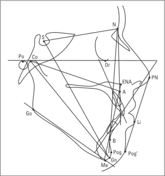
The cephalogram determined the contours of the following structures: Anterior limit of the frontal bone, frontonasal suture, nasal bones, orbit (with its posterior and inferior contours), mechanical porion, sella turcica, clivus, bony pal-ate (traced from the anterior nasal spine to the posterior nasal spine), anterior contour of the maxilla, mandibular condyle, posterior border of
mandibular ramus, lower border of mandibular body, anterior and posterior contours of the sym-physis, upper and lower central incisors (which were more proclined), all drawn with the aid of a template (3M Unitek®, Campinas, Sao Paulo, Brazil), and soft tissue profile (Fig 1).
After completion of the cephalograms us-ing the manual and digital methods the follow-ing cephalometric landmarks were traced as described by Araújo2 and Ferreira10 and illus-trated in Figure 1.
- Point S (Sella); point N (Nasion); point ANS (Anterior Nasal Spine); point Po (Porion); point Or (Orbitale); point A (Subspinale); point B (Supramentale); point Pog (Pogonion); Point Me (Menton); point Go (Gonion); point Gn (Gnathion); point Co (Condylion); point Pn (Nose tip), Li (Lower lip); point Pog’ (Soft Tis-sue Pogonion).
Once the landmarks had been traced, the lines and planes, depicted in Figure 1, could be obtained.
For this evaluation 14 measurements were selected, eight angles derived from the Tweed26
(FMA and IMPA); Steiner23 (SNA, SNB, ANB, 1.NA, 1.NB) and Downs9 (Y axis) analyses, and six linear measurements taken from the Stein-er,23 (1-NA, 1-NB); McNamara,17 (Gn, Co-A, LAFH) and Ricketts20 (LE-Li) analysis.
After performing the tracings, the angular and linear measurements were obtained with the aid of a protractor (ref. 701-401) (3M Unitek®, Campinas, São Paulo, Brazil). The data were then tabulated for subsequent statistical analysis.
digital methodology (dolphin)
The 50 cephalometric radiographs were scanned into digital format using an HP Scanjet G4050 and exported to the Dolphin Imaging® 11.0 software (Dolphin Imaging and Manage-ment Solutions, Chatsworth, Calif.). An indica-tor was used (Dolphin® Radiographic Film Cal-ibration Ruler) during image scanning to deter-mine the amount of expansion and establish a proportion for the scanned images. The images were converted to JPEG format and saved with maximum quality with the Dolphin Imaging® 11.0 program. The file size of the final image was about 200Kb, with 200 dpi resolution. A 19” LCD 1550V flat screen monitor (Sam-sung®, São Paulo, Brazil) was used for viewing the images. When necessary, images were en-hanced with brightness, contrast and magnifi-cation to identify areas with greater accuracy. The program illustrates all points and their tracing sequence, and allows users to magnify any specific areas.
In a first step, the researcher was properly calibrated by performing five sequential tracings until the technique was mastered. After calibra-tion, 50 cephalometric tracings were performed using Dolphin Imaging® 11.0.
After scanning the radiographs and register-ing the patients a specific analysis, called MB analysis, was developed especially for use in this study. This analysis encompasses the following steps: 1) Selecting the cephalometric radiograph,
2) Clicking on the command “digitize”, 3) Run-ning the custom analysis editor, 4) Selecting the option “Single Analysis” to create a custom analysis (Fig 2) based on the linear and angular measures proposed by Tweed, Steiner, Downs, McNamara, Ricketts, as mentioned above.
The 42 cephalometric landmarks required by MB analysis were traced and digitized using Dol-phin Imaging® 11.0 software.
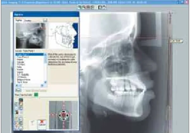
Before implementing the digital tracings it was essential to determine the start and end points of the ruler (100 mm) with the purpose of rendering the actual size of each radiographic image (Fig 3).
The program illustrates all points and their tracing sequence, and allows users to magnify any specific areas (Fig 4).
By joining the above points the digital trac-ings were performed and linear and angular val-ues obtained (Fig 5), which were accessed au-tomatically by selecting the “Meas” (measures) button. Subsequently these values were treated statistically.
statistical analysis
Data analysis
Evaluation of statistical differences between angular and linear measurements by the man-ual and digital methods was performed using Minitab software, version 14, and applying Stu-dent’s t-test. Intraexaminer error was assessed by means of ten new, randomly selected tracings (five manual and five digital) after 20 days. The data obtained at T1 and T2 were compared using Student’s t-test.
Results
Intraexaminer error results showed no sta-tistically significant difference at T1 and T2, as depicted in Tables 1 and 2.
disCussiOn
Cephalometry has contributed countless benefits to scientific research and the develop-ment of Orthodontics.
According to Albuquerque-Júnior and Almei-da,1 examiners can interfere significantly with systematic effects, affecting the reproducibility of cephalometric values. Silveira and Silveira22 FIGURE 2 - Creating a custom analysis using the “Single Analysis” option.
FIGURE 4 - Determining the points and performing the cephalometric tracing.
FIGURE 3 - Determining start and end points on the ruler (measurement standardization).
FIGURE 5 - Tracing and measurements generated by the program.
argue that one method to control errors in the replication of cephalometric measurements con-sists in calibrating examiners directly, and further suggest that such direct calibration be included in any scientific experiment. Tables 1 and 2 dis-play a comparison between measurements taken by the examiner in manual and digital cephalo-metric tracings at different times (T1 and T2), showing that no statistically significant differ-ence was found in any of the measurements in both groups.
These findings disagree with those of some authors1,3,16,25 who claim that in cephalometry error is a constant even when examiners have extensive experience.
In this study, the analysis of the results ob-tained when comparing the angular and linear cephalometric measurements taken in digital and manual tracings revealed values that were very close to the means and standard deviations, reflecting a nonsignificant p value for all magni-tudes (Tables 3 and 4). These findings support those of Chen5, Correia et al8 and Vasconcelos et al.27 Conflicting results were found by other authors6,13 whose data showed statistically sig-nificant differences, although accepted in clini-cal practice.
TABLE 3 - Comparison between the means and standard-deviations of angular measurements obtained from manual and computerized tracings.
TABLE 4 - Comparison between the means and standard-deviations of linear measurements obtained from manual and computerized tracings.
Variables Manual measure-ments mean (DP) Dolphin measure-ments (DP) p value
FMA 27.46 (5.33) 27.59 (5.11) 0.90 n.s. IMPA 96.27 (7.35) 95.50 (7.73) 0.61 n.s. SNA 82.75 (3.63) 82.56 (3.61) 0.78 n.s. SNB 78.75 (3.49) 78.55 (3.43) 0.77 n.s. ANB 3.99 (2.86) 4.00 (2.84) 0.98 n.s. 1.NA 27.73 (8.91) 26.95 (8.90) 0.66 n.s. 1.NB 30.96 (7.20) 30.06 (7.66) 0.54 n.s. Y Axis 59.57 (4.02) 60.15 (3.98) 0.47 n.s.
Variables Manual measure-ments mean (SD)
Dolphin
Measure-ments mean (SD) p value
1.NA 8.23 (3.20) 8.02 (3.22) 0.74 n.s.
1.NB 7.97 (3.44) 7.91 (3.41) 0.92 n.s.
Co-Gn 125.37 (7.55) 125.09 (7.81) 0.85 n.s.
Co-A 96.29 (5.22) 95.68 (5.71) 0.57 n.s.
LAFH 74.11 (7.37) 74.45 (7.41) 0.81 n.s.
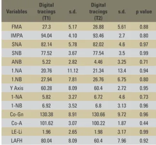
LE-Li 2.12 (3.76) 2.53 (3.56) 0.57 n.s. TABLE 2 - Comparison between the means and standard-deviations of linear and angular measurements obtained from digital tracings at T1 and T2.
(n.s.=non-significant, p>0.05). LE-Li = E Line-Lower lip.
(n.s.=non-significant, p>0.05). (n.s.=non-significant, p>0.05).
Variables
Digital tracings (T1)
s.d.
Digital tracings (T2)
s.d. p value
FMA 27.3 5.17 26.88 5.61 0.88
IMPA 94.04 4.10 93.46 2.7 0.80
SNA 82.14 5.78 82.02 4.6 0.97
SNB 77.52 3.67 77.54 3.5 0.99
ANB 5.22 2.82 4.46 3.25 0.71
1.NA 20.76 11.12 21.34 13.4 0.94
1.NB 27.94 7.81 26.76 6.75 0.80
Y Axis 60.28 8.09 60.4 2.72 0.95
1-NA 5.82 3.27 6.72 4.6 0.73
1-NB 6.92 3.52 6.8 3.13 0.96
Co-Gn 130.38 8.91 130.66 9.72 0.96 Co-A 101.62 3.07 100.22 1.87 0.44
LE-Li 1.96 2.65 1.98 3.17 0.99
LAFH 80.04 8.09 60.4 7.96 0.92
Variables
Manual tracings (T1)
s.d.
Manual tracings (T2)
s.d. p value
FMA 26.80 5.11 27.20 5.40 0.908
IMPA 95.40 4.67 95.20 4.21 0.945
SNA 83.00 5.29 83.00 4.69 1.000
SNB 77.50 3.87 77.90 3.29 0.865
ANB 5.50 2.69 5.10 2.92 0.828
1.NA 21.8 11.2 22.2 12.6 0.959
1.NB 28.20 7.92 29.60 8.73 0.798 Y Axis 59.70 2.39 60.60 1.52 0.503
1.NA 5.40 2.88 5.40 3.85 1.000
1.NB 6.80 3.47 6.60 3.21 0.927
Co-Gn 129.90 9.09 131.10 9.26 0.842 Co-A 102.10 1.67 102.40 2.07 0.808
LE-Li 1.50 3.64 1.30 3.75 0.934
LAFH 79.30 8.25 78.80 8.56 0.928 TABLE 1 - Comparison between the means and standard-deviations of linear and angular measurements obtained from manual tracings at T1 and T2.
mandibular incisors,1 or both.3,16 Brangeli et al3 and Martins et al16 argued that dental structures are difficult to locate and measurements of such structures have low reliability in both methods (manual and digital). In this study, the smallest p values were found in the Y-axis (p=0.47) and in incisor-related angular measurements (1.NB
p=0.54, IMPA p=0.61; and 1.NA p=0.61), as shown in Table 3, but can still be considered reli-able in both evaluation methods.
It is a known fact that locating points on the apexes of incisors poses some serious difficulty in both radiographic film and scanned images. The latter can be even more challenging due to the presence of gray shades that merge in this region. Even when software features such as filtering and zooming are used, the task of locating these points is even more difficult than in X-ray films.27 On the other hand, Albuquerque-Júnior and Almei-da1 and Chen et al5 argue that the computerized method is reliable as it exhibits lower error vari-ance than the conventional method. Forsyth et al,11 however, in 1996, asserted that errors in the identification of points, angular and linear mea-surements tend to occur more often in digital im-ages than in conventional radiography. Nonethe-less, since no significant differences were found in this study, the authors consider the digital method sufficiently reliable for use in Orthodontics.
Assessment of the linear values obtained in digital and manual tracings (Table 4) showed that this comparison did not yield any signifi-cant differences. Lower p values can be observed in the Co-A (p=0.57) and LE-Li (p=0.57) mea-sures. Collins et al7 found statistically significant differences in linear measurements but these authors compared the Dolphin measurements of scanned and photographed images and found linear distortions in the latter.
This study found that the digital method is reliable, corroborating most authors1,3,8,24,25,27 who compared different cephalometric tracing
methods and programs and indicated its use in orthodontic practice.
Nowadays, digitizing X-rays has become the preferred method to perform cephalomet-ric measurements. As technology evolves it be-comes increasingly easier for professionals to adapt to the many routine tasks of clinical prac-tice. This scientific investigation supports other studies published in the literature,5,8,25,27 which confirm the enhanced effectiveness provided by today’s technological resources.
This study evaluated the reliability of an-gular and linear measurements in manual and computerized cephalometric tracings performed with the aid of Dolphin Imaging® 11.0 software. However, further studies should be performed using this computer program since it features other tools for cephalometric tracing, such as overlays, predictive tracings for orthognathic surgery and profile manipulation, in addition to the options provided by the 3D program itself, which involves three dimensions.
COnClusiOns
According to the methods used in this study and the results achieved by comparing angular and linear measurements of manual and digital tracings it is reasonable to conclude that the cephalometric program Dolphin Imaging® 11.0 can be used reliably as an aid in diagnosing, plan-ning, monitoring and evaluating orthodontic treatment both in clinical and research settings.
Submitted: July 2010
1. Albuquerque HR Jr, Almeida MHC. Avaliação do erro de reprodutibilidade dos valores cefalométricos aplicados na
ilosoia Tweed-Merriield, pelos métodos computadorizado e
convencional. Ortodontia. 1998 set-dez;31(6):19-30.
2. Araújo TM. Cefalometria: conceitos e análises.
[dissertação]. Rio de Janeiro (RJ): Universidade Federal do Rio de Janeiro; 1983.
3. Brangeli LAM, Henriques JFC, Vasconcelos MHF, Janson GRP.
Estudo comparativo da análise cefalométrica pelo método
manual e computadorizado. Rev Assoc Paul Cir Dent. 2000 maio-jun;54(3):234-41.
4. Chen YJ, Chen SK, Chang HF, Chen KC. Comparison of
landmark identiication in traditional versus computer-aided
digital cephalometry. Angle Orthod. 2000 Oct;70(5):387-92. 5. Chen SK, Chen YJ, Yao CC, Chang HF. Enhanced speed
and precision of measurement in a computer-assisted digital cephalometric analysis system. Angle Orthod. 2004 Aug;74(4):501-7.
6. Chen YJ, Chen SK, Yao JC, Chang HF. The effects of diferences in landmark identiication on the cephalometric
measurements in traditional versus digitized cephalometry. Angle Orthod. 2004 Apr;74(2):155-61.
7. Collins J, Shah A, McCarthy C, Sandler J. Comparison of measurements from photographed lateral cephalograms and scanned cephalograms. Am J Orthod Dentofacial Orthop. 2007 Dec;132(6):830-3.
8. Correia AC, Melo MFB, Barreto GM, Oliveira JLG, Santos
TS. Estudo comparativo entre cefalometria manual e computadorizada em telerradiograias laterais. Rev Cir Traumatol Buco-maxilo-fac. 2008 abr-jun;8(2):61-8. 9. Downs WB. Variations in facial relationship: their signiicance
in treatment and prognosis. J Cancer Res Clin Oncol. 1995;121(8):452-6.
10. Ferreira FV. Cefalometria clínica. In: Ferreira FV. Diagnóstico e planejamento clínico. 6ª ed. São Paulo: Artes Médicas; 2004. 11. Forsyth DB, Shaw WC, Richmond S. Digital imaging of
cephalometric radiography, part 1: advantages and limitations of digital imaging. Angle Orthod. 1996;66(1):37-42. 12. Held CL, Ferguson DJ, Gallo MW. Cephalometric digitization:
a determination of the minimum scanner settings necessary
for precise landmark identiication. Am J Orthod Dentofacial
Orthop. 2001 May;119(5):472-81.
13. Lance QB, Palomo M, Badem S, Hans MG. A comparison of scanned lateral cephalograms with corresponding original radiographs. Am J Orthod Dentofac Orthop. 2006 Sep; 130(3):340-8.
RefeRenCes
Contact address
Faculdade de Odontologia da UFBA – Ortodontia e Ortopedia Facial Av. Araújo Pinho, 62, 7º andar – Canela
CEP: 40.110-150 – Salvador/BA, Brazil E-mail: [email protected]
14. Loiola M. Ortodontia contemporânea: livro eletrônico em capítulos atualizados via internet. São Paulo; 2009. [acesso em 2009 nov 14]. Disponível em: http://ortodontia-contemporanea.blogspot. com/2009/01/dolphin-imaging-management-solutions.html. 15. Mahi CRW, Drago MC. Comparação entre cefalometria manual e
computadorizada. Stomatos. 2003 jan-jun;9(6):15-20. 16. Martins LP, Santos-Pinto A, Martins JCR, Dias A. Erro de
reprodutibilidade das medidas cefalométricas das análises de
Steiner e de Ricketts, pelo método convencional e pelo método computadorizado. Ortodontia.1995 jan-abr;28(1):4-17. 17. McNamara JA Jr. A method of cephalometric evaluation. Am J
Orthod Dentofacial Orthop. 1984 Dec;86(6):449-69.
18. Pereira CB. Breve resenha histórica da informática na ortodontia.
Nota-se o envolvimento, entrelaçado, com a cefalometria
radiográica, pois esta foi uma das precursoras e impulsionadoras da informática na ortodontia. [Acesso 2006 jan 10]. Disponível
em: http://www.cleber.com.br/histor2.html.
19. Pereira CB. O futuro da Odontologia - Parte V. Na era da
informática. História da informática na Odontologia. Rev ABO
Nacional. 2008;17(5).
20. Ricketts RM. Esthetic, environment, and the law of lip relation. Am J Orthod Dentofacial Orthop. 1968 Apr;54(4):272-9.
21. Rodrigues C Jr, Pereira CB. A informática no consultório da
Ortodontia: diretrizes. Ortodontia Gaúcha. 1998 jul-dez; 2(2):143-52.
22. Silveira HL, Silveira HE. Reproducibility of cephalometric measurements made by three radiology clinics. Angle Orthod. 2006 May;76(3):394-9.
23. Steiner CC. Cephalometric for you and me. Am J Orthod Dentofacial Orthop. 1953 Oct; 30(10):729-55.
24. Tanikawa C, Yagi M, Takada K. Automated cephalometry: system
performance reliability using landmark-dependent criteria. Angle Orthod. 2009 Nov;79(6):1037-46.
25. Trajano FS, Pinto AS, Ferreira AC, Kato CMB, Cunha RB, Viana FM. Estudo comparativo entre métodos de análise cefalométrica
manual e computadorizada. Rev Dental Press Ortod Ortop Facial. 2000 nov-dez;5(6):57-62.
26. Tweed CH. Was the development of the diagnostic facial triangle
as an accurate analysis based on fact or fancy? Am J Orthod. 1962 Nov;48:823-40.