Julho de 2012
Hugo Manuel de Almeida Vaz Pereira
Mestrado Integrado em Ciências de Engenharia Electrotécnica e de Computadores
Interoperability on Low Power Devices
Dissertação para obtenção do Grau de Mestre em Engenharia Electrotécnica e de Computadores
Orientador: Adolfo Sanchez Steiger Garção,
Professor Catedrático, FCT-UNL
Co-Orientador: Pedro Miguel Negrão Maló,
Professor Assistente, FCT-UNL
Júri:
Presidente: Prof. Doutor José António Barata de Oliveira
Arguente: Prof. Doutor Tiago Oliveira Machado de Figueiredo Cardoso
ii Interoperability on Low Power Devices
Copyright © Hugo Manuel de Almeida Vaz Pereira, Universidade Nova de Lisboa
A Faculdade de Ciências e Tecnologia e a Universidade Nova de Lisboa têm o direito, perpétuo e sem limites geográficos, de arquivar e publicar esta dissertação através de exemplares impressos reproduzidos em papel ou de forma digital, ou por qualquer outro meio conhecido ou que venha a ser inventado, e de a divulgar através de repositórios científicos e de admitir a sua cópia e distribuição com objectivos educacionais ou de investigação, não comerciais, desde que seja dado crédito ao autor e editor.
iii
v
Queria dedicar esta tese á minha família. Ao meu Pai e Mãe, por serem o meu exemplo a seguir e por todo o amor e força que nunca deixaram de dar. À minha Irmã, pela paciência e pelo carinho e amor que nunca deixou de demonstrar. À Cris, por estar incondicionalmente disponível e presente na minha vida. À minha avó Maria pela grande mulher que é e por todo o amor incondicional que sempre me deu. À tia Bia por nunca deixar de me dar força sempre que precisei. O meu sincero Obrigado por tudo e por fazerem de mim o que sou hoje!
À Joana por toda a dedicação, paciência, apoio e amor incondicional que sempre demonstrou, Obrigado! Ao Manel por ser o meu amigo de sempre. Ao Gordo, por nunca ter deixado de me ouvir quando mais precisei. Ao Bueno, por ser quem é. Ao Central por estar sempre aqui quando é preciso. À Raquel por tudo o que fez, nunca vou esquecer. À Inês Pinheiro por ser a minha amiga mais ocupada. Ao Jester por ser o meu eterno vizinho e amigo! À Andreia pelas conversas até às tantas! Ao Luís por ser o meu melhor amigo ausente! Ao Eusébio por ter enterrado o pastel comigo ao longo do curso! Ao Careca por estar sempre disponível quando precisei! Ao “Bad Boy” Caixinha por todos os póneis malditos! Ao Monhé por ser o meu companheiro de trabalho! Á Telma e ao Nuno pelas horas de riso e disponibilidade! Ao Kelia por ser o meu amigo mais parvinho! À Telma por todos os momentos de risos! Ao Stage por ser um grande bot! À Inês Ferreira por ser única. Ao Pelo de rato por ser sempre verdadeiro! Aos Beetoques por serem a minha equipa! Ao Paulinho por ser o meu primo irmão! Ao David e a todos os Fagulhas!
Ao Tiago, Márcio e Spread o meu obrigado pela paciência e disponibilidade que nunca me faltou! Ao Pedro Maló e ao Bruno Almeida, pela exigência e rigor demonstrada ao longo do trabalho, foi um prazer trabalhar convosco. Ao Departamento de engenharia electrotécnica e de computadores pelas condições proporcionadas para a finalização do curso. A todos os amigos que não mencionei, mas que estiveram sempre presentes.
vii
Abstract
Model transformation is the process of turning one data format into another according to a specification that contains the operations needed to accomplish it. Therefore it assumes a relevant role on handling interoperability on an “Internet of Things” environment composed by interconnected heterogeneous things with heterogeneous information. However, operate interoperability specifications on this environment is challenging, because model transformation technologies were developed considering an environment composed of devices with processing power and memory, as opposed to the environment exposed. The proposed solution consists in a specific approach, the clear separation of run-time and design time processes and the redefinition of formats used to describe model data and interoperability specification without changing their information. To do so an execution engine architecture is specified, able to execute model transformations according to a lite model data format and an interoperability specification defined as part of the solution.
Keywords: Internet of Things, Interoperability, Heterogeneity, low power devices, Execution Engine.
ix
Resumo
Transformação de modelos é o processo de transformar um formato de dados noutro de acordo com uma especificação que contém as operações necessárias para fazê-lo. Então, este processo assume um papel relevante para suportar interoperabilidade num ambiente “Internet of Things” composto por coisas heterogéneas interconectadas, com informação heterogénea. Contudo, operar especificações de interoperabilidade neste ambiente é desafiante, dado que as tecnologias de transformações de modelos foram desenvolvidas considerando um ambiente composto por dispositivos com poder de processamento e memória, ao contrário do ambiente anteriormente exposto. A solução proposta consiste numa abordagem específica, que se baseia na separação clara de processos em run-time e design-time e pela redefinição de formatos usados para descrever os dados do modelo e a especificação de interoperabilidade sem mudar a informação contida nos mesmos. Para tal, foi especificada a arquitectura de um motor de execução capaz de executar transformações de modelos de acordo com um formato de dados lite e uma especificação de interoperabilidade definidos como parte da solução.
Palavras-Chave: Internet of Things, Interoperabilidade, Heterogeneidade, Dispositivos de baixo consumo, Motor de transformação de modelos.
xi
Chapter 1 Introduction ... 1
1.1 Motivation Scenario: Plug and Interoperate ... 1
1.2 Problem: Operate Interoperability Specifications in a low power device environment ... 4
1.3 Work Methodology ... 5
1.4 Dissertation outline ... 7
Chapter 2 - State of the Art ... 9
2.1 State of the Art Review ... 9
2.1.1 Individual Review ... 9
2.1.2 Synthesis ... 17
2.2 Advancement ... 18
Chapter 3 - Interoperability on Low Power Devices ... 21
3.1 ATL compilation ... 23
3.1.1 ASM text file ... 23
3.2 Lite Language... 24
3.3 Execution Engine ... 26
3.3.1 Logical Architecture Specification ... 26
3.3.2 Detailed architecture ... 30
3.3.3 Architecture Module Sequence ... 30
Chapter 4 - Testing and Validation ... 33
4.1 Testing Methodology ... 33
4.2 Proof of Concept Implementation ... 36
4.3 Test Definition and Execution ... 36
4.3.1 Lite language translation ... 37
4.3.2 Model transformation execution ... 43
4.4 Verdict ... 47
Chapter 5 - Conclusions and Future Work ... 49
5.1 Future Work... 52
xiii
Figure 1.1 - Application domains and relevant major scenarios, based on (Atzori, Iera et al. 2010) 1
Figure 1.2 - An application scenario of Internet of Things ... 2
Figure 1.3 - Source to target information exchange through Interoperability specification ... 3
Figure 1.4 - Work approach used in this thesis ... 6
Figure 2.1 - ATC Virtual Machine architecture, retrieved from (Lorenzo, Luna et al.) ... 11
Figure 2.2 - EMF engine architecture, retrieved from (Jouault and Kurtev 2006)... 12
Figure 2.3 - Processing Kermeta language ... 14
Figure 2.4 - An overview of the Viatra2 transformation execution, retrieved from (Varró, Balogh et al. 2006)... 16
Figure 2.5 - Viatra2 execution overview, retrieved from (Varró, Balogh et al. 2006) ... 16
Figure 3.1 – Approach example ... 22
Figure 3.2 - ASM structure, retrieved from (ATLAS 2005) ... 23
Figure 3.3 - ASM Compilation process ... 24
Figure 3.4 - Expression hierarchy for conversion example, retrieved from (Preden and Pahtma 2009) ... 25
Figure 3.5 – Execution Engine Architectural Solution ... 26
Figure 3.6 - Example of module with API and Caller Interface ... 27
xiv
Figure 3.8 - Model Handler ... 28
Figure 3.9 – Virtual Machine ... 29
Figure 3.10 - Detailed Architecture ... 30
Figure 3.11 - Sequence Diagram of the Execution Engine ... 32
Figure 4.1- Global View of the Conformance Testing Process, based on (Technology 1991) ... 34
Figure 4.2 - Lite Language translation Test 1 - Model description ... 38
Figure 4.3 – Lite Language translation Test 1 - Model data ... 39
Figure 4.4 - Lite Language translation Test 1 - Execution Outcome ... 39
Figure 4.5 - Lite Language translation Test 1 – Translation Model Data Outcome ... 40
Figure 4.6- Lite Language translation Test2 - Model description ... 40
Figure 4.7 - Lite Language translation Test 2 - Model data ... 41
Figure 4.8 - Lite Language translation Test 2 - Execution Outcome ... 41
Figure 4.9 - Lite Language translation Test 2 – Translation Model Data Outcome ... 42
Figure 4.10 - Model transformation execution test 1 - Initial conditions ... 44
Figure 4.11 - Model transformation execution test 1 - Model data ... 45
Figure 4.12 - Model transformation execution test 2 - Initial conditions ... 45
Figure 4.13 - Model transformation execution test 2 - Model data ... 46
Figure 4.14 - Model transformation execution test 3 - Initial conditions ... 46
xv
Index of Tables
Table 2.1 - Method synthesis and features coverage ... 18
Table 3.1 – Constants for the conversion example, retrieved from (Preden and Pahtma 2009) ... 25
Table 4.1 - Example of a TTCN-2 based table test ... 35
Table 4.2 - Example of a test case ... 35
Table 4.3 - Lite language translation - Test definition ... 37
Table 4.4 - Lite language translation - Test execution ... 38
Table 4.5 - Lite Language translation Test 1 - Tag definition table ... 39
Table 4.6 - Lite Language translation Test 2 - Tag definition table ... 41
Table 4.7 - Lite Language translation Test 3 - Tag definition table ... 42
Table 4.8 - Model transformation execution - Test definition ... 43
xvii ACG ATL virtual machine Code Generator API Application Programming Interface ATC Atomic Transformation Code ATL Atlas Transformation Language
ASM Assembly
AST Abstract Syntax Tree
EMF Eclipse Modeling Framework EMOF Essential Meta Object Facility EMP Eclipse Modeling Project
GT Graph Transformation
GRIS Group for Research in Interoperability of Systems IDE Integrated Development Environment
IOT Internet of Things JVM Java Virtual Machine
MDA Model Driven Approach
MDE Model Driven Engineering
MDR MetaData Repository
OCL Object Constraint Language
OMG Object Management Group
OSI Open System Interconnection QVT Queries, Views and Transformations SQL Structured Query Language
xviii
UML Unified Modeling Language
IonLPD – Interoperability on Low Power Devices 1
Introduction
Chapter 1
We shall not walk away from our future. We shall harness the power of the IoT to shape the future together.” From Gérald Santucci on The Internet of Things: A Window to Our Future
1.1 Motivation Scenario: Plug and Interoperate
“Internet of Things” intends to enhance things, going from books to cars, electrical devices to food, of our everyday life with information and interconnect them. Thus the users can access the data to analyze or act according to all aspects of the physical world (Karl Aberer 2006). Accordingly, everyday things are connected, have an identity, are readable, can acquire intelligence, gather information from different sources and act accordingly to that information, with user requirement or autonomously (Kopetz 2011).
As Luigi Atzori (Atzori, Iera et al. 2010) stated “Potentialities offered by the IoT make possible the
development of a huge number of applications”. “Internet of Things” is an emerging technology that is
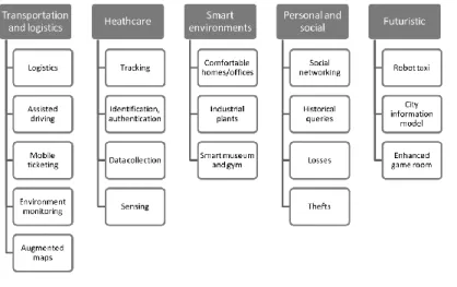
used in several scenarios. According to Atzori and Iera (Atzori, Iera et al. 2010) there are 5 relevant application scenarios to take into consideration such as transportation and logistics, healthcare, smart environments, personal and social and futuristic as shown in the Figure 1.1.
Chapter 1 - Introduction
IonLPD – Interoperability on Low Power Devices 2
One application consists in a comfortable home scenario. In this house, according to the profile of each inhabitant, the coffee will be ready at the right time; the bathtub will be filled with water at the desirable temperature and the requested time; the right media will be played through television or radio, according to the preferences of the user; the heat of the room will be adapted according to the weather and the user profile; and in addition the electric equipment’s will be automatically turned off in order to provide an optimization of the energy consumption (Atzori, Iera et al. 2010). This will lead to a maximization of the user’s comfort according to the environment status and the user profile.
In these “Internet of Things” scenarios the existence of several actuators and sensors is a requirement, however it mostly lead to a heterogeneous environment with non-standardized data. Since, due to the lack of data standard in this field, each manufacturer operates data in a different way. This conducts to a large number of heterogeneous devices and sensor networks and consequently generates an interoperability problem in the “Internet of Things” domain.
Figure 1.2 - An application scenario of Internet of Things
Interoperability “is the ability of two (or more) systems or components to exchange information and to
use the information that has been exchange” (IEEE 1990). For example, considering the same
domestic environment composed of sensors and actuators, as shown in Figure 1.2, with the aim to prevent a house fire, a smoke detector (sensor) is installed and sends data to a water sprinkle (actuator). The actuator receives information from the sensor in an integer value form and acts according with it. The presence of carbon monoxide is detected by the sensor, however it can be detected through several types of concentration units, such as g/mL, g/cm3 or kg/L. According to the
IonLPD – Interoperability on Low Power Devices 3 scenario, how will the water sprinkler interpret information and act accordingly? It can not, since there is no interoperability between the sensor and the actuator, even though the data exchange has been done correctly.
In order to assure interoperability in the “Internet of Things”, the Plug and Interoperate concept has been developed and defined by the research group Uninova - GRIS. Therefore, Plug and Interoperate aims to allow that devices from different manufacturers could be plugged to a heterogeneous network and interoperate with it without the need of remanufacturing every device that composes the network. For this proposal, the system must transform disparate data into a known data format which arises due to the existence of non-standardized data, readable and usable in a heterogeneous environment.
The previous scenario presented can be used as an example of the Plug and Interoperate. Considering that a new sensor enters in the house network. This sensor uses a specific data format unknown to the house network, consequently the information will not be spread through the network. The data exchange in the network will only be possible if exists a specification that tells the system how to convert the unknown data format to a known one in the network. Thus this specification assumes a relevant role in the Plug and Interoperate solution and it will be referred as interoperability specification.
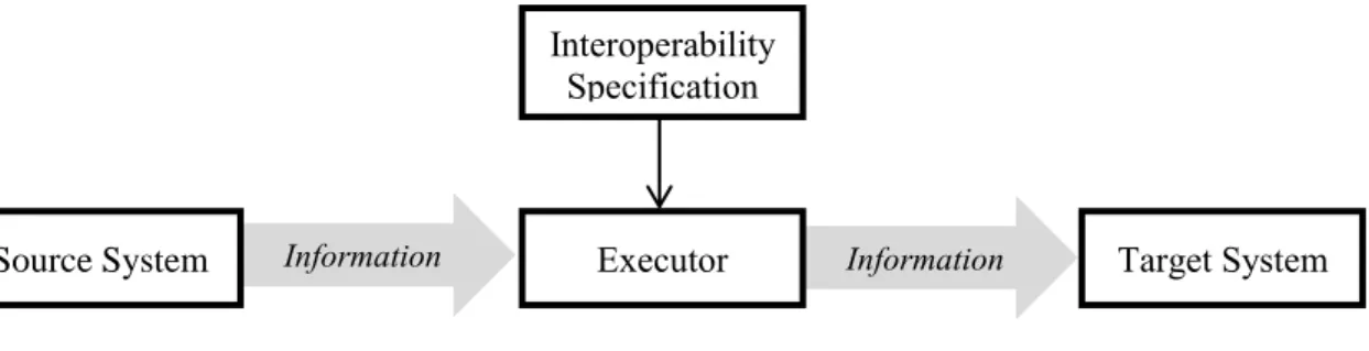
Interoperability specification is a method of supporting the transformation of one data format into another one in order to achieve interoperability between different data formats. The executors are responsible for interpreting interoperability specifications and data formats, transforming the last one into another data format. In Figure 1.3 is represented an information exchange between a source system (sender) and a target system (receptor), by using an executor to transform the information according to the interoperability specification, allowing the information exchange.
Figure 1.3 - Source to target information exchange through Interoperability specification Information
Information
Source System Executor Target System
Interoperability Specification
Chapter 1 - Introduction
IonLPD – Interoperability on Low Power Devices 4
1.2 Problem: Operate Interoperability Specifications in a low power device
environment
The Plug and Interoperate concept is executed in the network in an “Internet of Things” environment where the executor is present. However and taking into consideration the previous environment, the implementation of such executor in this context is not trivial due to the resource constrains, such as low processing power and memory (Gsottberger, Shi et al. 2004), associated to heterogeneous devices that compose the environment.
The devices referred are normally battery powered and with wireless connection to provide information anywhere at any time and with flexibility to be installed in different places. Consequently, there is no need of networked power supply, neither physical network connection. Since the devices power is supplied by battery, a low processing unit is required to extend their activity for the longest time as possible for information gathering. On the other hand the incremental code migration1 has been achieved using XML (Bray, Paoli et al. 2000), these devices lack the RAM to store even the simplest XML elements. Thus, the executor has to be implemented considering the low processing power and memory constrains of the device.
Besides the presented issues related with resource constrains, there is still the need to handle disparate data formats which can be achieved with the operation of interoperability specifications. However, these operations are developed in different languages, such as ATL (Bézivin, Dupé et al. 2003) and QVT (OMG 2003), that were developed without considering the constrains of these devices.
Therefore the challenge is to understand and find new routes to operate interoperability specifications in these resource constrained devices to provide interoperability in heterogeneous environments. This challenge leads to the following research question:
This research question will support the development of this master thesis and answering it will be the challenge of the work. In order to achieve the previous goal, the problem needs to be characterized as follows.
1
add, remove or replace code fragments in a remote program
IonLPD – Interoperability on Low Power Devices 5 Resource constrains
The operation over interoperability specifications, developed over different languages, such as ATL (Bézivin, Dupé et al. 2003) or QVT (OMG 2003), were developed without any resource constrains concern. Thus, these operations are done in personal computers that use a resourceful processor meant to be flexible and used for a wide range of applications and with a lot of memory resources. Low power devices compose the “Internet of Things” environment and are different from personal computers because they have low processing power and low memory, due to the battery power and design constrains, respectively. Accordingly, the problem is how to operate interoperability specifications considering the resource constrain of devices that compose the environment.
Disparate data format handler
The lack of standard data formats in a heterogeneous environment generates the need to support disparate data formats. This occurs because devices manufacturer only provide the data formats without semantic details. For example, considering one low power device in the heterogeneous environment that uses an UML data format and other device uses a XML data format. To exchange information between them, the interoperability specification needs to be defined and processed otherwise the communication does not occur between both in this environment.
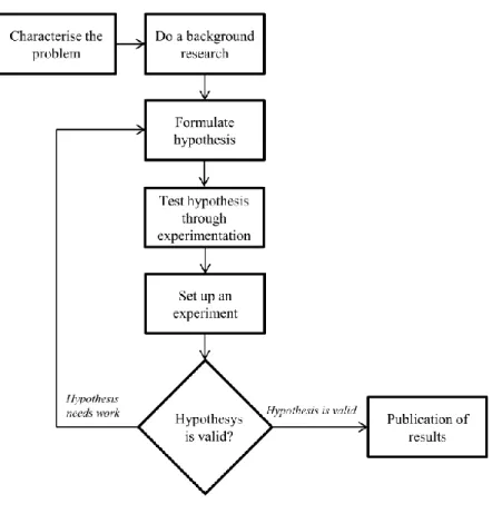
1.3 Work Methodology
The Work Methodology used in this thesis is inspired on the Scientific Method described in (Schafersman 1997). This work approach, as shown in Figure 1.4, is composed of the following steps:
1. Characterise the problem;
2. Do a background research;
3. Formulate hypothesis;
4. Set up an experiment;
5. Test hypothesis through experimentation;
6. Draw conclusions;
Chapter 1 - Introduction
IonLPD – Interoperability on Low Power Devices 6
Figure 1.4 - Work approach used in this thesis
The steps presented in the picture will be defined and explained as following:
1. Characterise the problem
In this step, a significant problem is identified and so are its respective characteristics. It will end with a research question that will be the base of the research work. The problem identified in this thesis is how to operate interoperability specifications in a low power device.
2. Do background research
This step is where scientific data from prior work, associated to the research question, is exposed. This leads to the requirement of gathering information about execution engines that enables interoperability in heterogeneous low power device environments.
3. Formulate hypothesis
The formulation of hypothesis is one of the steps in this work approach. Based on the background research the hypothesis must be an “informed, testable, and predictive solution to a scientific
IonLPD – Interoperability on Low Power Devices 7 problem” (Schafersman 1997) that explains the characterization of the problem, in a way that can be
tested. In this thesis, the hypothesis focuses on the problem of operate interoperability specifications on heterogeneous low power devices.
4. Set up an experiment
This step consists in an experiment setup in order to validate the formulated hypothesis. This experiment is used as a proof-of-concept defined by taking into account the characterization of the problem and the formulated hypothesis.
5. Test hypothesis through experimentation
In this step, several tests over the experimentation were defined in order to obtain the outcome of it. This outcome is analysed and interpreted considering the characteristics of the problem in order to validate the hypothesis purposed. If the results can be quantitative and qualitative analyzed, the outcome should be applied to the results.
6. Draw of conclusions
After the test is completed, it is important to analyse the outcome of the experimentation and verify the validity of the hypothesis. This analysis can enframe in the hypothesis or not, which can lead to the confirmation of the hypothesis or the denial of the same. If the hypothesis is confirmed then it will answer the research question according to experimentation. Otherwise, it must return to point 3 where a new hypothesis is formulated.
7. Publication of results
In this step, the publication of results is made according to the outcome of the experimentation in the research work. This step only occurs if the outcome answers the hypothesis defined in the thesis.
1.4 Dissertation outline
This thesis is divided in five chapters and since the first chapter, presents the motivating scenario and the problem of the thesis, a brief description on the other four will be given:
Chapter 1 - Introduction
IonLPD – Interoperability on Low Power Devices 8
State of the Art - The second chapter provides technologies that implement the concept of operate interoperability specification associated to the research question. In the end of the chapter, an analysis of each state-of-art element will be given according to the problem defined in the first chapter and the features that each element provides to this work.
Interoperability on Low Power Devices - The third chapter presents the proposed solution to provide an answer on how to operate interoperability specifications on low power devices. It starts with the presentation of the concept behind the solution. Then, it is the solution with their respective description. Finally it ends with a sequence diagram that provides a global view of the solution.
Testing and Validation - The fourth chapter provides the tests used to validate the formulated hypothesis. It begins with the description of the methodology used to test the hypothesis. A description of the implemented proof of concept and the test definition and execution will be presented. Then the results are presented and it is verified if the initial objectives were fulfilled through an analysis of the test results.
Conclusions and Future Work - The final chapter of this work presents a summary of the dissertation, giving a highlight of the most important aspects of the research as well as a potential direction for future research regarding the obtained results.
IonLPD – Interoperability on Low Power Devices 9
- State of the Art
Chapter 2
2.1 State of the Art Review
In this chapter an extensive research is made in order to identify which solutions do exist to operate interoperability specification in low power devices. Several solutions were identified but only five will get the main focus due to the fact that these are suitable approaches to achieve the research goal. The elements in this research use Model Driven Interoperability concepts, which are summarized next.
Model Driven use models to describe elements of a system with a concrete viewpoint, expressed with the aid of a well-defined language. Furthermore, it can be characterized by model transformations that represent relations between models and meta-models. In this work the models are the information that is transformed, meta-models are the language that describes the information and model transformation is described by an interoperability specification defined between those models and meta-models (Kleppe, Warmer et al. 2003). In order to operate interoperability specifications execution engines are used. The execution engine intends to enhance software interoperability, by executing the translation of one data language to another one according to the interoperability specifications.
2.1.1 Individual Review
Several transformation languages with one or more execution engines were considered:
Atomic Transformation Code Virtual machine - The ATC VM is responsible to interpret and to process the ATC language file providing QVT- based transformations.
Eclipse Modeling Framework Virtual Machine – The EMF VM is a byte code interpreter responsible to transform Ecore data files using ATL language to describe model transformations.
Kermeta – Kermeta is an executable meta-modelling language designed to define operational semantics of meta-models and structures specification.
Chapter 2 – State of the Art
IonLPD – Interoperability on Low Power Devices 10
Viatra2.0 – Viatra2.0 is a model transformation engineering framework that aims at supporting the execution of transformations between several modeling languages.
Atomic Transformation Code Virtual machine
ATC VM is a virtual machine for QVT (Queries, Views and Transformations)-based transformations which is responsible for performing transformations on several model data types. It has been developed over the Open Canarias S.L. a model transformation project which target goal was to comply with OMG-MDA, therefore the QVT specification was targeted. The Virtual-Machine technology drive by its own byte-code model transformation language named Atomic Transformation Code (ATC) which is the main characteristic of the solution purposed (Sánchez-Barbudo, Sánchez et al. 2008).
The ATC VM architecture is based on the Eclipse Core and the Eclipse Modeling Framework (EMF) (Steinberg, Budinsky et al. 2008) and it is currently available as a set of Eclipse plug-ins. The Eclipse Modeling Framework project is a Java-based modelling framework and code generation facility for building tools and other applications based on structured data model. EMF is implemented in java and provides tools and runtime support to produce a set of Java classes and adapter classes of the model.
The ATC Virtual machine (ATC VM) also known as Virtual Transformation Engine (VTE) is responsible to interpret and to process the ATC language file. The ATC language file derives from a translation of the meta-models registered on the Eclipse Modeling Framework to an ATC language file provided by the ATC tool. ATC language file contains all the semantics of any programming language decision, loops and own data types. It is a byte code model transformation language that contains the interoperability specification and the meta-model data. The ATC Virtual Machine and its respective layered architecture summarized is shown in Figure 2.1.
IonLPD – Interoperability on Low Power Devices 11
Figure 2.1 - ATC Virtual Machine architecture, retrieved from (Lorenzo, Luna et al.)
Analysis:
Regarding the ATC tool from an architectural point of view, it can be concluded that it is a Java-based architecture implemented on top of the Eclipse platform and Eclipse Modeling Framework (EMF) (Steinberg, Budinsky et al. 2008). The Eclipse platform is a multi-purpose plugin-based Java IDE, and the Eclipse Modeling Framework (EMF) is a full-fledged Java platform for aid Model Driven application development, that provides among other things, an abstraction layer to provide access to several model languages types. Both elements described leads to the fact that the Virtual Transformation Engine (VTE) is implemented on top of Java-based technologies. One problem of Java is the need of suitable run-time environment, a Java Virtual Machine (JVM), which requires significant resources in terms of memories and computing power (Uhrig and Wiese 2007).
The purpose of the VTE is to interpret ATC model and execute the ATC language model transformation instances, so it does not directly process other transformation languages or model languages. It can however process other model transformation languages and model languages registered in the Eclipse Modeling Framework (EMF), for which ATC translation support has been provided. This translation support is achieved through a traditional parsing, a model generator and a model transformation, the whole process described, requires memory and processing power (Gsottberger, Shi et al. 2004) in order to be accomplished.
Eclipse Modeling Framework Virtual Machine
One of the technologies found, was the EMF Virtual machine, this virtual machine is the responsible for providing model transformations for several model data files. The EMF virtual
Chapter 2 – State of the Art
IonLPD – Interoperability on Low Power Devices 12
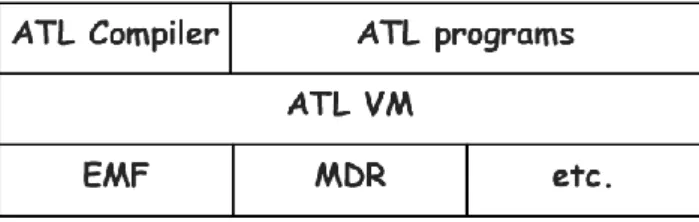
machine is a byte code interpreter responsible to transform Ecore data files to describe information and using an ATL language to describe the model transformation. It is part of the Eclipse Modeling Project (EMP), which focuses on the evolution and promotion of model-based development technologies within the Eclipse community by providing a unified set of modelling frameworks, tools and standards implementations.
The EMF virtual machine tool architecture is based on the Eclipse Core and it is implemented on top of the Eclipse Modeling Framework (EMF) (Steinberg, Budinsky et al. 2008) and Netbeans MetaData Repository (MDR) (Matula 2003), which can be seen in Figure 2.2. The EMF and the MDR, between other things, are model handlers implemented in Java that consist on an abstraction layer to provide access to the XML-based model (e.g. ecore data files). This Virtual Machine could also be based on other model handlers as suggested by the “etc.” box in Figure 2.2. The ATL compiler, also known as ATL VM Code Generator (ACG), is implemented on top of the EMF VM and is a domain specific language designed to express the compilation of an ATL program model transformation into ASM code executable by the EMF Virtual Machine (Jouault and Kurtev 2006).
The EMF virtual machine is derived from the current ATL Virtual Machine and is a byte code interpreter which manages OCL and ATL type’s hierarchy, providing model transformations, supported by an execution environment that provides the realisation of operations necessary to the model transformation accomplishment. The necessary inputs in order to achieve that goal, on the EMF Virtual Machine, are the meta-model and model registered in the Eclipse Modeling Framework (EMF) Repository and the interoperability specification, described in the only model transformation language EMF Virtual Machine can process directly, the ASM file. Typically all inputs are XML-based files, where the model and meta-model are interpreted by a model handler and the interoperability specification by the EMF Virtual Machine itself.
Figure 2.2 - EMF engine architecture, retrieved from (Jouault and Kurtev 2006)
Analysis:
Architecturally, the EMF Virtual Machine is based on the Eclipse core, and is implemented on top of Eclipse Modeling Framework (EMF) (Steinberg, Budinsky et al. 2008) and Netbeans MetaData Repository (MDR) (Matula 2003). Both technologies are full-fledged java components based
IonLPD – Interoperability on Low Power Devices 13 platform for aid application development, leading to the conclusion that in order to provide these technologies to the EMF Virtual Machine architecture, the Java Virtual Machine will be a requirement to process the Java language, leading to a significant resource usage (Uhrig and Wiese 2007).
The EMF Virtual Machine tool is responsible to provide model transformation, according to an interoperability specification expressed by an ASM file, which is the only file the EMF Virtual Machine can process directly. The ASM file is an output of ACG that results from the compilation process of a XML-based ATL file, this process requires parsing, interpretation and transformation into XML-based ASM file, although “XML-based parsing requires certain computing power” (Gsottberger, Shi et al. 2004). Once the ASM is obtained, the EMF Virtual Machine parses it, in order to access the interoperability specification information.
On the other hand, in order to execute a model transformation, besides the interoperability specification the EMF Virtual Machine needs to have access to model and meta-model data. This information is provided by the Eclipse Modeling Framework (EMF) (Steinberg, Budinsky et al. 2008), Netbeans MetaData Repository (MDR) (Matula 2003) or any other model handler, which virtually gives support to any data format. The problem is that models and meta-models are mostly described with the aid of a XML-based file, making the parsing of information a requirement for model handlers to provide data access to the EMF Virtual Machine, leading to a high resource usage (Gsottberger, Shi et al. 2004) in order to accomplish this process.
Kermeta
Kermeta has been developed as a core language for an MDE (Model Driven Engineering) platform. It is an executable meta-modelling language, which is designed to define both operational semantics of meta-models and structures specification. This action language can specify the body of operations in meta-models complying with the OMG Essential Meta Object Facility (EMOF) (OMG 2003). This technology provides tools for transforming its meta-models from and to EMOF and Ecore meta-models. The tool is included in the modelling layer of the RNTL platform, and used in projects like OpenDevFactory and Speeds (Drey, Faucher et al. 2009).
The Kermeta architecture is built as an extension to Eclipse Modeling Framework (EMF) (Steinberg, Budinsky et al. 2008) within the Eclipse development environment. The Eclipse Development environment is a Java IDE to aid application development, where the Eclipse Modeling Framework (EMF) is integrated. The Eclipse Modeling Framework (EMF) unifies Java,
Chapter 2 – State of the Art
IonLPD – Interoperability on Low Power Devices 14
XML and UML, technologies so that they can be used together to build better integrated software tools, as the Kermeta virtual machine. The Eclipse Modeling Framework (EMF) is implemented using Java, but it is used to implement development tools for other languages, in this case Kermeta language.
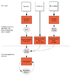
The Kermeta language is supported by a Kermeta virtual machine, based on the Java Virtual Machine, responsible to provide model transformations according to operations specified by the Kermeta language. In order to execute a model transformation, the kermeta tool requires 2 inputs, the interoperability specification expressed by a .kmt file (kermeta language) and the meta-model expressed by a registered meta-model in the Eclipse Modeling Framework Repository (EMF). Regarding the meta-model, it is a XML-based file processed by the Eclipse Modeling Framework directly, however Kermeta uses an internal mapping in order to import Ecore model as Kermeta model. On the other hand the interoperability specification, specified by the Kermeta language, is processed directly by the tool itself, as seen in the Figure 2.3.
Figure 2.3 - Processing Kermeta language
Analysis:
Analysing Kermeta from an architectural point of view, it can be concluded that the technology possesses a Java-based architecture and is also implemented on top of one, Eclipse Modeling Framework (EMF) (Steinberg, Budinsky et al. 2008). In order to process the elements that compose the Kermeta Virtual Machine architecture, a Java Virtual Machine is needed to execute the Java language, leading to the requirement of processing power and memory (Uhrig and Wiese 2007).
IonLPD – Interoperability on Low Power Devices 15 The model transformation execution process in the Kermeta Virtual Machine is achieved recurring to two inputs, the Kermeta language and the meta-model or Kermeta model. The Kermeta language is processed by the Kermeta Virtual Machine, through the parsing of the Kermeta language file resulting into an Abstract Syntax Tree (AST) (Jones 2003) and then loaded and translated into a Kcore model. The process described, parsing and translation, are resource intensive processes (Gsottberger, Shi et al. 2004).
On the other hand this tool accesses the meta-model information, through the Eclipse Modeling Framework (EMF) (Steinberg, Budinsky et al. 2008). The EMF is responsible to provide the Kermeta Virtual Machine the ability of processing several meta-model types, since the Virtual Machine natively integrates Ecore definitions. However it requires a translation of the EMF meta-model into a Kermeta meta-model, leading to the conclusion that this process requires the parsing and translation of information requiring processing power in order to be accomplished (Gsottberger, Shi et al. 2004).
Viatra2.0
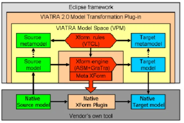
“Viatra2.0 (VIsual Automated model TRAnsformations) is a general-purpose model transformation engineering framework that aims at supporting the entire life-cycle, i.e. the specification, design, execution, validation and maintenance of transformations within and between various modeling languages and domains in the MDA“ (Varró, Balogh et al. 2006). Viatra2.0 is available as part of
the Eclipse GMT Subproject and is being developed at the Fault Tolerant Systems Research Group at the Budapest University of Technology and Economics, and it was inserted in several projects such as the project HIDE.
Viatra2 have a Java based architecture, where there are three main modules, the Eclipse Modeling Framework (EMF) (Steinberg, Budinsky et al. 2008), the Viatra2.0 Model transformation Plug-in and the Viatra Model Space, as shown in Figure 2.4. Viatra2.0 is implemented on top of the Eclipse Modeling Framework (EMF) (Steinberg, Budinsky et al. 2008) and the model transformations in Viatra2.0 tool are primarily executed within the framework. In order to provide that model transformation execution in consonance with the Eclipse Modeling Framework (EMF) (Steinberg, Budinsky et al. 2008) the tool is fitted with the Viatra2.0 Model transformation plug-in. This element is the main responsible to handle and transform heterogeneous meta-models and their respective data into a Viatra2.0 data format, which is achieved through XML, Model and Xform parsers and their respective interpreters. The Viatra2.0 Model Space is responsible to provide model transformation execution.
Chapter 2 – State of the Art
IonLPD – Interoperability on Low Power Devices 16
Figure 2.4 - An overview of the Viatra2 transformation execution, retrieved from (Varró, Balogh et al. 2006)
The main purpose of Viatra Model Space is to provide a model transformation execution engine to the Viatra2 tool. To achieve model transformation the engine requires 2 inputs, an interoperability specification and a meta-model. The interoperability specification is expressed by a Graph Transformation rules (GT) or an Abstract State Machines (ASM) (Varró and Balogh 2007) this file requires the interpretation and compilation by the engine in order to be accessible to it. The meta-models in this technology are mostly represented through Ecore, but the Eclipse Modeling Framework (EMF) (Steinberg, Budinsky et al. 2008) and the Viatra2.0 Model Transformation Plug-in provides support to several meta-models data types. Regarding the execution Viatra2.0 enables the separation of design (and validation) and execution time, as shown in Figure 2.5.
Figure 2.5 - Viatra2 execution overview, retrieved from (Varró, Balogh et al. 2006)
Analysis:
The Viatra2 tool, from an architectural point of view, is integrated in the Eclipse Modeling Framework (EMF) for general-purpose model transformation engineering framework, to support various model transformation languages and domains in the MDA. It has built-in support, through the Viatra2.0 Model transformation Plugin, for different data formats and different transformation languages, giving this tool the ability to support heterogeneous data formats and interoperability
IonLPD – Interoperability on Low Power Devices 17 specifications. The problem is that both framework are Java-based technologies, requiring resource intensive processes in order to be executed correctly (Uhrig and Wiese 2007).
Viatra2 tool requires the interoperability specification and the meta-model so it can execute a model transformation. In order, to provide the model transformation execution there is the requirement to access the information in the inputs of the tool. To achieve this goal the tool recurs to XML, XForm and Model parsers to compilers and interpreters. The whole process is done in design time and requires memory and computing power to be achieved (Gsottberger, Shi et al. 2004). The model transformation execution is done in runtime and is described by the translation of the inputs and the execution according to an interoperability specification, this translation. The translation described is achieved through a model transformation and a rule interpreter, being this a resource intensive process (Gsottberger, Shi et al. 2004).
2.1.2 Synthesis
Presented and described each state-of-art element, it is now time to resume the main features of each element relating it to each one of the characteristics of the problem: Handling disparate data formats and Resource constrains.
In order to handle disparate data formats, all the technologies have a common solution expressed in their architecture, the Eclipse Modeling Framework (EMF) (Steinberg, Budinsky et al. 2008). The main difference between the technologies studied is the way they use EMF. The ATC Virtual Machine and Kermeta use this technology as a model handler and model repository, and both have a translation support from EMF models to their native language type. The EMF Virtual Machine directly access to the Eclipse Modeling Framework, or any other model handler to process model information, providing to this technology an extensive support to heterogeneous data. Viatra2 access information from the EMF through the Viatra2 Model Transformation Plugin layer, which was designed to provide the translation of languages to the Viatra2 model transformation engine and to provide support to other languages the EMF cannot process.
Regarding the execution engine, all of the technologies studied, need the parsing of their respective inputs information, leading to the requirement of having processing power to achieve this goal (Gsottberger, Shi et al. 2004). Besides that these execution engines rely on a Java-based architecture requiring a Java Virtual Machine to process the Java language, leading to a significant resource usage (Uhrig and Wiese 2007) by all the technologies addressed.
A brief analysis of each element according to each feature of the problem, previously defined, is shown in Table 2.1. Each row of the table represents the elements studied and each column the features of the problem.
Chapter 2 – State of the Art
IonLPD – Interoperability on Low Power Devices 18
Table 2.1 - Method synthesis and features coverage
Resource Constrains Disparate data handler
ATC VM
No, since it is implemented on top of Eclipse and the EMF project and possesses a Java-based architecture. There is also the requirement of parsing inputs.
Yes, it uses a byte-code model transformation language, this language contains all the semantics of any programming language, which makes possible the support of any model language by this tool
EMFVM
No, the EMF Virtual Machine tool is based in resource intensive technologies, such as XML parsers, and Eclipse Ecore.
Yes, this technology supports only ecore data files, but since it is based on several model handlers, virtually any model is possible to be supported by this tool.
Kermeta
No, the tool is based in resource intensive technologies, such as XML parsers, Eclipse Core and the Eclipse Modeling Framework. The Kermeta virtual machine has a Java-based architecture.
Yes, since the Kermeta meta-models can be easily transferred from/to other systems. This tool can virtually support any data type.
Viatra2
No, the Viatra2 tool is integrated in the Eclipse Modeling framework, and it recurs to a XML serializer and a XForm parser, in order to parse the models data an then interpret it.
Yes, the Viatra2 is integrated in the Eclipse framework in order to support various model transformation languages and domains in the MDA.
2.2 Advancement
After reviewing and analysing all elements of the state of art, it can be concluded that none of the technologies presented can solve all the features of the problem described. In order to provide a suitable solution, different functionalities of each technology were selected with the purpose of fulfill all the requirements previously stated.
Regarding the handling of disparate data formats, all systems rely on the Eclipse Modeling Framework (EMF) (Steinberg, Budinsky et al. 2008). Among the studied elements, the EMF Virtual Machine is the only technology that directly access to the information on the Eclipse Modeling Framework and is architecturally designed to support countless model handlers. Virtually
IonLPD – Interoperability on Low Power Devices 19 this characteristic of the EMF Virtual Machine grants support to any data format, providing the most suitable approach to the solution.
In terms of resource constrains, none of the technologies studied fulfill the needs of the solution but there are, in some of the elements, interesting characteristics to contribute to it. One interesting approach is the separation of design time and execution time provided by Viatra2 which can severely contribute to a resource aware solution. Another interesting approach is made by the ATC VM and EMF VM, which consists in the translation of the interoperability specification to a byte-code format. This byte-byte-code format directly provides, to the virtual machine, the operation necessary to the transformation execution without the need of translation. The only problem is both virtual machines require a XML-Parser to process the interoperability specification.
One major issue regarding the resource constrains is the constant need of XML-parsers in all technologies studied. To avoid this issue, the need of redefining interoperability specification, models data to a new lite format, is of extreme importance. Since EMF Virtual Machine is the technology that provides better support to disparate data, it will be used as a reference on the solution purposed.
Chapter 2 – State of the Art
IonLPD – Interoperability on Low Power Devices 21
- Interoperability on Low Power
Chapter 3
Devices
The purpose of this work is to support interoperability specification execution on low power devices. To accomplish this goal, two different approaches are taken in consideration:
Execute the minimum of processes in run-time - This is made to enable low power devices to execute the only the run time processes required to accomplish a model transformation execution.
Use of a lite language - This language is designed to overcome the processing and memory limitations that exist on low power devices.
The first approach relies on the minimum execution of processes in run time. This approach arises to allow some run time demanding processes to be executed by resourceful devices in design time. This stems from the model transformation execution done by the EMF Virtual Machine2, (Steinberg, Budinsky et al. 2008) which requires intensive resource usage and far too demanding processes, like file compilation and XML-parsing.
The second approach relies on the use of a lite language. This language is created due to the fact that the EMF Virtual Machine execution requires access to important data, such as model data3, to provide a model transformation execution. Two problems arises from this, the storage of that information and the XML-parsing to access that data. These procedures require computing and memory power, so they should therefore, be avoided on low power devices.
2
A model transformation execution engine
Chapter 3 – Interoperability on Low Power Devices
IonLPD – Interoperability on Low Power Devices 22
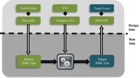
The model transformation defined by Eclipse consists in an interoperability specification (described through an ATL) between two models (described through Ecore). Those models contain data that is operated through an execution engine to provide a model transformation. In order to provide model transformations on an embedded system a solution is presented on Figure 3.1.
Figure 3.1 – Approach example
This chapter goal is to describe the presented solution and will be structured as follows:
ATL compilation - Designed to express the compilation of a model transformation language into an executable code that will be processed by the Execution Engine.
Lite Language - Designed to express the information contained in a XML-file on a simple lite format.
Execution Engine - Responsible to execute a model transformation and handle lite models data. Design time Run time ATL Compiled ATL Source XML Lite Source Ecore Data XML Target XML Lite Target Ecore Data XML
IonLPD – Interoperability on Low Power Devices 23
3.1 ATL compilation
A valid way to use ATL compilation in low power devices is to provide a model transformation language in a textual assembler file that will be interpreted by the execution engine. Unlike this, EMF Virtual Machine uses an assembler language file to describe a model transformation expressed in a XML data type.
The compilation process is based on ATL Virtual Machine specification (ATLAS 2005) and it consists in a compilation of an ATL file to a set of instructions readable by the execution engine. These instructions are:
Operand Stack Handling - This instruction provides a number of instructions that enable direct manipulation of the operant stack. It defines instructions like push, pop, load, store, among others.
Control Instructions - This cause the ongoing execution to continue from an instruction that may be different from the previous one. It defines instructions like if, goto, iterate,
enditerate and call.
Model Handling Instructions - This instruction set is dedicated to models and model elements handling. It defines instructions like new, get, put and findme.
3.1.1 ASM text file
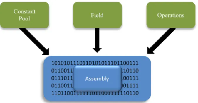
The Eclipse Modeling Framework Virtual machine is designed to read the ASM file format and correctly perform the operations specified therein. The ASM file is an assembly file encoded by a XML. Thus the ASM file is composed by XML elements in an ordered structure that contains a constant pool (cp), a field and one or more operation fields, as shown in Figure 3.2.
Chapter 3 – Interoperability on Low Power Devices
IonLPD – Interoperability on Low Power Devices 24
This ASM file uses a reference system that connects every XML element. Therefore the approach followed to avoid the XML parsing on low power devices consists in interconnecting every XML element and turning the ASM into an assembly language file as shown in Figure 3.3.
Figure 3.3 - ASM Compilation process
3.2 Lite Language
Interpreting a model data defined in a XML requires processes like parsing and interpretation, although “XML-based parsing requires certain computing power” (Gsottberger, Shi et al. 2004). Therefore a lite language in a textual format is defined to represent the model data information in another format.To do so, the XML fields and parameters are identified with hexadecimal tags, and the XML file is compiled to a hexadecimal format, to reduce the use of intensive resource processes to interpret the model data. Both files contain the same information but are described in different formats.
The compilation process is based on (Preden and Pahtma 2009), that consists on an appropriate structuring and encoding of data suitable for use by Wireless Sensor network nodes. In this a general data format is adopted which allows any type of data to be transmitted and interpreted by any node. In the solution the data fields in the message are identified by tags describing the contents of the field. The semantics of the tags must be defined and assigned with a specific meaning before system deployment.
The structure of the data is based on object-subject-value expressions. The expressions are three tuples , a brief description of each tuple is given:
Object - describes the situation parameter type, such as, situation types or other object types(e.g. in case of a mathematical equation the mathematical operation are also objects)
1010101110110101011101100111 0110011101100111011001110110 0111011001110110011101100111 0110011101100111111011001111 1101100111111011001111110110 011111101100111 Assembly Operations Field Constant Pool
IonLPD – Interoperability on Low Power Devices 25 Subject - Refers to another expression, in order to enable an expression hierarchy. Value - contains the value of the situation parameter
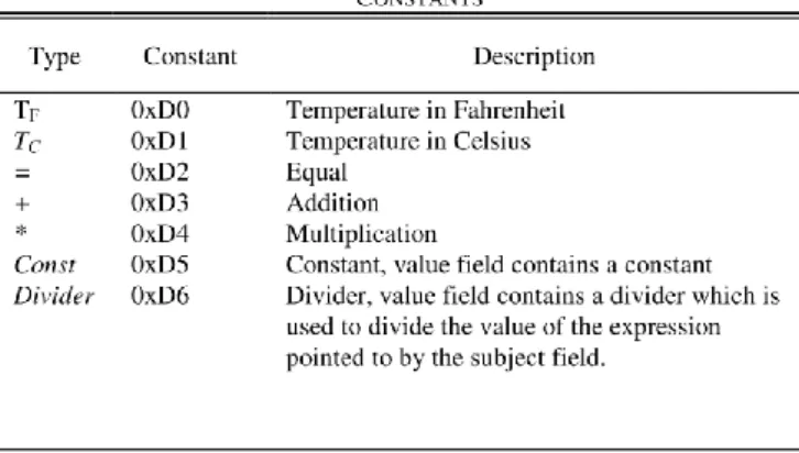
For further understanding an example will be given. The objective of this example is to create a complex expression that given a temperature in Celsius units, will convert the temperature to Fahrenheit units. For that, there is the requirement of defining the tags, as shown on Table 3.1.
Table 3.1 – Constants for the conversion example, retrieved from (Preden and Pahtma 2009)
Since the tags are defined, there is the need of defining the expression , that converts Celsius ( ) units to temperature in Fahrenheit units ( ). In order to express the equation in the expression format outlined above, the use of constants listed in Table 3.1 is a requirement. The constants in the table are arbitrarily chosen for the example only. Using the constants from Table 3.1 the following expressions can be formed.
The following expression hierarchy can be visible in Figure 3.4.
Figure 3.4 - Expression hierarchy for conversion example, retrieved from (Preden and Pahtma 2009)
Chapter 3 – Interoperability on Low Power Devices
IonLPD – Interoperability on Low Power Devices 26
3.3 Execution Engine
The Execution Engine presented in the Interoperability on Low Power Devices is based on the EMF Virtual Machine architecture (Wagelaar 2011) but with changes to be suitable to low power devices. In order to understand the architecture a brief description, on the main modules, is presented:
Control - This module is responsible to control the flow of information to execute the model transformation.
Model Handler - The Model Handler module provides primitives to handle models data. Virtual Machine - The Virtual Machine module is responsible to execute the model
transformation operations.
The architecture and the described modules are presented in Figure 3.5.
Figure 3.5 – Execution Engine Architectural Solution
3.3.1 Logical Architecture Specification
The Logical Architecture Specification provides a description of the logical modules presented in the system. Each logical module is described with their purpose, methods and workload description. The Figure 3.6 represents a basic example of a logical module (Module 1). The upper block is an API that represents a set of methods that are available to other modules to use. The bottom block is a Caller Interface that represents methods that the module uses to communicate with other modules. Each module description provided in this work follows the structure presented in this section.
Execution Engine
Control Model Handler
IonLPD – Interoperability on Low Power Devices 27
Figure 3.6 - Example of module with API and Caller Interface
3.3.1.1 Control
The control module is responsible to monitor the data flow of the execution engine. The control module is the maestro of the execution engine, since it assigns “work” to other modules in order to make the whole process of the model transformation execution occur in consonance to what is described in the interoperability specification. It invokes methods from every module presented in the execution engine.
The Figure 3.7 shows this module composition.
Figure 3.7 – Control
The following interface is an API:
Request Handler Interface
The Request Handler Interface is an API that provides methods to enable a model transformation execution. These methods use the model data and the lite interoperability specification as an input to start the execution of the transformation process.
Module 1
Caller Interface API
Request Handler Interface
Model Handler Interface Virtual Machine Interface
Chapter 3 – Interoperability on Low Power Devices
IonLPD – Interoperability on Low Power Devices 28
Each of the following interfaces are caller interfaces:
Model Handler Interface
The Model Supplier Interface is a caller interface that invokes methods to load, access or change data of the model.
Virtual Machine Interface
The Virtual Machine Interface is a caller interface that invokes methods to execute interoperability specification operations.
The workload of this logical module starts at the Request Handler API. Thus, the Control module will invoke a method, through the Model Supplier Interface, to load the model data. Afterwards, it will process the interoperability specification and act according to the information interpreted.
Depending on the information processed the Control module may use the Model Supplier caller interface and the Virtual Machine interface, to access or change model data and to invoke existing methods on the Virtual Machine, respectively. Once the interoperability specification is processed it will require the output of the execution.
3.3.1.2 Model Handler
The Model Handler logical module is responsible for interpreting, exporting and providing model data to the execution engine. The interpreting function is designed to receive model data, analyse it and construe model information readable by the system. The exporting function does the opposite, since it gathers the system model data and turns it into model data so it can be exported as an output of a model transformation. It is also responsible to provide or change specific model elements data to the execution engine.
The Figure 3.8 shows this module composition.
Figure 3.8 - Model Handler Model Interface
IonLPD – Interoperability on Low Power Devices 29 Each of the following interfaces are API’s:
Model Interface
The Model interface is an API that provides methods to load a model data and to get and set data over specific fields of an interpreted model data to the system. It also provides methods to retrieve an entire model according to a system constructed model.
The workload of this logical module starts through the Model Interface API with the loading of a model data that will be stored in memory. Once the model data is loaded to memory, the module will provide methods to get and set specific model data information. In the end of the model transformation execution process, this module is responsible to provide methods to retrieve the translated model data.
3.3.1.3 Virtual Machine
The Virtual Machine is responsible to execute interoperability specification instructions over model data according to information provided by other modules.
The Figure 3.9 shows this module composition:
Figure 3.9 – Virtual Machine
The following interface is an entry interface:
Execution Provider Interface
The Lite Language interface is an API that provides methods to execute an instruction over specific model data.
This logical module is responsible to provide methods to execute instructions over a specific model data. It all starts in the Execution Provider Interface where the method to execute an instruction is called, afterwards the module requires access to specific model data in order to execute that instruction. Once the result of the execution is achieved, the module stores the outcome of the operation in memory.
Virtual Machine
Chapter 3 – Interoperability on Low Power Devices
IonLPD – Interoperability on Low Power Devices 30
3.3.2 Detailed architecture
The set of logical modules described in the previous section with their respective interfaces provide a new detailed overall architecture of the execution engine, as showed in Figure 3.10.
.
Figure 3.10 - Detailed Architecture
3.3.3 Architecture Module Sequence
Each module individually performs a specific task, however to meet the requirements proposed for the execution engine they must work as one. The purpose of this section is to provide a description over the overall functionality of the execution engine with the aid of an UML sequence diagram (Fowler and Scott 2000). On the sequence diagram of the architecture, every main module is represented through a lifeline block and the memory is represented through an entity. The actions are represented by a closed-end arrow, and the returns of those actions are represented through a dashed line and an open-end arrow.
The workflow of the execution engine starts at the Control module since this is the logical module responsible to handle new model transformation requests. These requests require the existence of a lite version of the interoperability specification data (ATL) and a lite version of the model data
Execution Engine
Control
Request Handler Interface
Virtual Machine Interface Model Supplier Interface
Model Handler
Model interface
Virtual Machine
IonLPD – Interoperability on Low Power Devices 31 (Data) as an input, so that the model transformation execution can be performed. Once the request is made the Control module invokes a method on the Model Handler Module to load model data to memory.
At this point, the interoperability specification still has not been interpreted and processed, but since the model data is loaded on the memory, all conditions are gathered to start the execution of a model transformation. The Control Module will be responsible to interpret the interoperability specification. That interpretation requires the reading of an instruction list contained in the interoperability specification file. All instructions must be read and processed so that the model transformation execution could be accomplished.
For each instruction contained in the interoperability specification, the Control module must analyse which actions to execute according to the instruction provided.
If the instruction is a “get”, the Model Handler logical module will load data to memory so that the virtual Machine can use it to process an instruction.
If the instruction is a “set”, the Model Handler logical module will set a new value on the model data information, according to information contained in memory.
If the instruction is not a “set” or a “get”, the Control module will invoke a method, with the instruction as an input, on the Virtual Machine module, so that the virtual machine execute that instruction and retrieve the result of it to memory.
Once all instructions are processed, the Control Module will request the Model Handler module the output of the execution process. The workflow of the architecture when executing a model transformation is represented in the Figure 3.11.
Chapter 3 – Interoperability on Low Power Devices
IonLPD – Interoperability on Low Power Devices 32