THE RELEVANCE OF QUALITY CONTROL IN SERVICES
OF HEMODYNAMICS AND INTERVENTIONAL CARDIOLOGY*
Eara de Souza Luz1
, Lucía Viviana Canevaro2
, Nadya Maria Prado Damasceno Ferreira3 , Julio Eduardo Campos4
OBJECTIVE: To evaluate the performance and quality of images of a x-ray equipment utilized in interventional radiology, by means of some tests of quality control. MATERIALS AND METHODS: Measurements have been performed on a Philips Integris H3000 x-ray equipment dedicated to interventional procedures in the hemodynamics laboratory of a hospital in Rio de Janeiro, RJ, Brazil. Leeds test objects have been used to evaluate the image quality. Dosimetric measurements have been developed with a Radcal 9015 dosimetric system. RESULTS: In high and normal modes, the air kerma rates have been different from the expected results. In some cases, values have not been affected by the use of different magnification modes. The images quality evaluation has showed different results from those recommended by technical standards. This could lead to the acquisition of poor quality images besides an increase in the radiation exposure levels for both patients and staff. CONCLUSION: The results have shown the importance of a periodical quality control testing, al-lowing the monitoring of the x-ray equipment performance and evaluation of radiation exposure levels for both patients and staff. The results suggest the need of a revision of the x-ray images acquisition system. Keywords: Interventional radiology; Hemodynamics; Quality control.
A importância do controle de qualidade em serviços de hemodinâmica e cardiologia intervencionista. OBJETIVO: Avaliar o desempenho de um equipamento de raios X utilizado em radiologia intervencionista e a qualidade de imagem produzida, aplicando alguns testes de controle de qualidade. MATERIAIS E MÉTO-DOS: O equipamento de raios X testado foi da marca Philips (Integris H3000), do serviço de hemodinâmica de um hospital do Rio de Janeiro. Foram utilizados objetos de teste de Leeds para avaliar a qualidade da imagem, e um sistema Radcal 9015 para medições dosimétricas. RESULTADOS: Nos modos high e normal, os valores medidos das taxas de kerma no ar foram diferentes dos esperados. Em alguns casos, os valores das taxas medidas não foram afetados pelo uso de diferentes modos de magnificação. A avaliação da qua-lidade da imagem apresentou resultados diferentes dos valores recomendados pelas normas. Isto pode levar à obtenção de imagens de menor qualidade e ao aumento da exposição à radiação de pacientes e profissio-nais. CONCLUSÃO: Os resultados mostraram a importância da aplicação periódica de testes de controle de qualidade, que permitem monitorar o desempenho do equipamento e estimar a exposição dos pacientes e trabalhadores. Os resultados obtidos sugerem a necessidade de uma revisão no sistema de aquisição de imagens do equipamento.
Unitermos: Radiologia intervencionista; Hemodinâmica; Controle de qualidade. Abstract
Resumo
* Study developed at Instituto Militar de Engenharia and Ins-tituto de Radioproteção e Dosimetria – Comissão Nacional de Energia Nuclear, Rio de Janeiro, RJ, Brazil.
1. M.Sc. in Nuclear Engineering, Instituto Militar de Engenha-ria.
2. D.Sc. Nuclear Biosciences, Instituto de Radioproteção e Dosimetria – Comissão Nacional de Energia Nuclear.
3. D.Sc. in Physics, Instituto Militar de Engenharia. 4. MD, Cardiologist, Instituto Militar de Engenharia. Mailing Address: Eara de Souza Luz. Praça General Tibúrcio, 80, Praia Vermelha. Rio de Janeiro, RJ, 22290-270 – Brazil. E-mail: [email protected]
Received February 17, 2006. Accepted after revision May 31, 2006.
INTRODUCTION
Interventional radiology involves diag-nostic and/or therapeutical interventions guided by means of percutaneous or other access, and usually performed under local anesthesia and/or sedation, using a
fluoro-scopic image to localize a lesion or treat-ment site, the fluoroscopy plying the main role of monitoring the procedure, controlling and documenting the therapy(1). It is one of
the radiodiagnosis methods which give patients highest radiation doses, and where the exposure to radiation is more critical for the practitioners. The percutaneous access is performed by means of a guided catheter inserted by the physician. The catheter in-sertion up to the treatment site, as well as the whole diagnostic and therapeutical pro-cedure, is performed under fluoroscopy, whose images are displayed on monitors both inside and out of the room. Because of the need for iodine contrast injection, and their high degree of complexity, the procedures require the support of assistant
So, the optimization of the practices in interventional radiology is a critical aspect that should not be disregarded. Quality control procedures constitute a tool in the process of optimization of the radiological protection in the practices, by means of monitoring of the different parameters in-fluencing the equipment performance, the radiation doses both for patients and prac-titioners, and the images quality. The qual-ity control allows the monitoring and main-tenance of the quality necessary for diag-nostic or therapeutical purposes of the interventional procedures in question(2,3).
The Brazilian legislation concerning radio-logical protections in radiodiagnosis — Ministry of Health Order (Portaria) no. 453/98(4) — establishes few requirements regarding quality control in interventional radiology. In April of 2003, the Agência Nacional de Vigilância Sanitária (National Agency for Sanitary Vigilance) published the Resolution no. 64(5) with some
recom-mendations about procedures of quality control for diagnostic services, including some tests in fluoroscopy. Performing pe-riodical testing is not a routine practice in the Brazilian hospitals yet.
The objective of the present study was to evaluate the performance of a x-ray equipment utilized in interventional radi-ology, applying some quality control tests.
MATERIALS AND METHODS
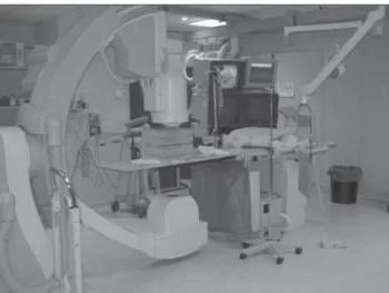
The present study has been developed in a Philips Integris H3000 model fluoro-scopic equipment (Figure 1) installed in a hemodynamics service of a large hospital in Rio de Janeiro, RJ, Brazil. The equip-ment operates in the following modes: con-tinuous low and normal, and pulsed high, 13 cm, 18 cm and 23 cm magnification modes (also called lens or zoom mode), digital cine image acquisition, and expo-sure control. The fluoroscopy modes deter-mine the dosing rates delivered by the x-ray beams. So, for a single exposure time, the high mode should deliver to the patient a higher dose than the low and normal modes. The magnification modes allow an increase in spatial resolution of images of the region to be studied. It is important to note that the lower the magnification mode, the higher the patient dose to allow a same
image quality. The values of 13 cm, 18 cm and 23 cm represent the diameter of the image intensifier input screen utilized.
In equipment evaluated in the present study, the controllers for the arc movements and distance between the x-ray tube and the images intensifier are coupled with the table. The equipment has two video moni-tors inside the room for visualizing the pro-cedures (Figure 2). The video monitor at left is utilized for images freezing, while the video monitor at right displays real time image during the procedure. For the proce-dures optimization, the quality of the im-ages must meet the quality criteria accord-ing to the objective to be reached.
One of the ways to estimate the radia-tion dose delivered to the patients is mea-suring the amount of energy deposited per
Figure 1. U-arc Philips H 3000 equipment utilized in interventional radiology with an image intensifier, two overhead monitors and patient table with controllers.
Figure 2. Equipment being operated by practitioners (physician at left, technician and nurse at right) in the hemodynamics room.
mass unit, denominated “air kerma”, ex-pressed in milliGray (mGy). Due the dy-namic nature of this procedure, in fluoros-copy, it is more appropriate to measure the “air kerma rate” (in units of mGy/min) than simply the air kerma.
Dosimetric tests were performed to evaluate the air kerma rate in the patient’s skin entrance, in the image intensifier in-put, and image quality test for evaluating high- and low-contrast spatial resolutions and distortion. Also the half-value layer (HVL) was evaluated.
Measurements of skin entrance and image intensifier input air kerma rates
and/or after equipment repairs, under nor-mal operational conditions. The measure-ment of the image intensifier input air kerma rate yields an estimate of x-ray equipment performance.
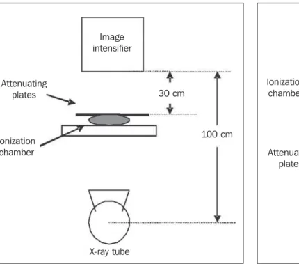
A Radcal dosimetric system consisting of a 9015 electrometer and a 10X5-60cc ionization chamber was utilized, with the ionization chamber positioned towards the x-ray beam. The reading is made by the electrometer. For simulating the presence of a patient, a 1mm-thick copper plate was utilized. The plate, as well as the patient, attenuates the x-ray beam (Figure 3). The skin entrance air kerma rate was measured for 18 cm and 23 cm magnifying modes (image intensifier diameter) which are the most utilized in procedures of this hemo-dynamics service. The x-ray tube was po-sitioned at 100 cm from the image intensi-fier, with the ionization chamber at 30 cm from the image intensifier input, and 1 cm above the table, within the radiation field. The copper plate was placed over the ion-ization chamber (Figure 3).
For evaluating the image intensifier in-put air kerma rate, the ionization chamber was fixed in the intensifier input, and the x-ray tube was positioned at 85 cm from the image intensifier. The copper plate was
placed on the examination table for simu-lating the patient. Exposures were per-formed registering the air kerma rate in mGy/min measured by the ionization chamber in low, normal and high fluoro-scopic modes, as well as the kilovoltage (kVp) and amperage utilized for 18 cm and 23 cm magnification modes (Figure 4).
Evaluation of high-contrast spatial resolution and low-contrast discrimination
The estimation of high- and low-con-trast resolutions was performed with the aid of test objects developed by University of Leeds for semiquantitatively analyzing x-ray images quality(6,7). The test objects bear
details of different materials and thick-nesses inside. For the testing, each test object is fixed to the image intensifier in-put screen. It is recommended that tests are ran at each half-year or every time the equipment is serviced.
The high-contrast spatial resolution is evaluated in terms of line pairs per milli-meter (lp/mm), discriminating alternating black and white line pairs into groups of different spatial frequencies on the image displayed on the monitor screen. The low-contrast resolution is evaluated in terms of
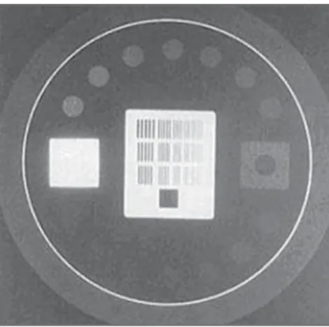
percentage of contrast between circles of different densities (details) and their back-ground on the image displayed on the monitor screen or image register system. Figure 5 shows the image of a Leeds TOR (TVF) test object.
For determining the high-contrast reso-lution of the image displayed on the moni-tor screen of the x-ray equipment in ques-tion, one has identified the group of line pairs where two lines can be separately identified. For determining the number of lp/mm that the images system can resolve, the Leeds test object manual includes a table of equivalences between the group identified on the image and the correspon-dent number of lp/mm.
The low-contrast resolution evaluation consists of the counting of visible circles (those differentiated from the background) on the image displayed on the monitor screen. For the low-contrast resolution, the Leeds test objects manual(6,7) includes a
table with the contrast degree as a function of the number of circles identified on the image, and suggests a 4% value as a lower acceptance threshold. The results were compared with those established by the order (Portaria) 453 (Table 1). However, it is important to note that the Order
Figure 3. Positioning of an ionization chamber and attenuating plates in re-lation to images intensifier and x-ray tube during measurement of skin en-trance air kerma rate.
Image intensifier
Attenuating plates
Ionization chamber
X-ray tube
30 cm
100 cm
Figure 4. Positioning of ionization chamber and attenuating plates in relation to image intensifier and x-ray tube during measurement of image intensifier input air kerma rate.
Image intensifier
Attenuating plates Ionization chamber
X-ray tube
(Portaria) 453/98 generalizes the recom-mendations for a conventional fluoro-scopic system, but acceptable thresholds should be defined by the physicist-physi-cian responsible by the quality control for each x-ray equipment, considering the equipment specific application and the re-quirements of each interventional tech-nique utilized (cardiology, vascular medi-cine, neuroradiology, etc.).
Distortion
This test is aimed at determining whether the imaging system introduces geometrical distortion on images displayed on the avail-able monitor screens. In case this distortion exists, the Leeds TO M1 test object allows the quantification of the distortion degree. If the distortion is significant, the image on the monitor screen, mainly the internal monitor in the hemodynamics room, may lead to misinterpretation during the proce-dure. The Leeds TO M1 is a wire grid (ra-diopaque material) test object that allows the observation of a square matrix image on the monitor (Figure 6), where the distances between vertical and horizontal lines are uniform and known.
The distortion on the internal monitor of the hemodynamics room was evaluated. The test was performed with the test object fixed to the images intensifier input screen so that the central square was positioned closer to the irradiation center. On an im-age without geometric distortion, all the squares should present the same dimen-sions, corresponding to perfect squares. The evaluation is aimed at identifying the
largest visible square matrix (n x n squares) on the image. Then, the main and second-ary diagonals of the largest square matrix were measured with a ruler, as well as those of the squares in the center and extreme points of the matrix (lower left and right, and upper left and right). A square region (seven squares on the horizontal plane, and seven on the vertical plane) was evaluated. The distortion was calculated in the region where the diagonals of the extreme points squares are larger in length. Based on the measured values, the image distortion on the monitor was determined by means of equation 1:
Figure 5. Image from a Leeds test object utilized to evaluate high- and low-contrast resolutions on fluoroscopic equipment monitor screens(6).
Figure 6. Image from a Leeds test object utilized to evaluate distortion on fluoroscopic equipment monitor screens(6).
ate low-energy photons which do not con-tribute to the images formation, but rather to the dose delivered to the patient. The minimum total filtration of a diagnostic x-ray equipment must have is at least 2.5 mmAl(4). The objective of the HVL mea-surement is to evaluate whether the x-ray tube has an adequate filtration. This test must be performed once a year and after repairs(4).
The device utilized in this test was a Radcal 10X5-60 ionization chamber coupled with an electrometer, Al filters and a tape measure. The measurements were performed for an 18 cm magnification in the normal scopy mode. The ionization chamber was positioned above the table, under the x-ray beam, at a 45 cm distance from the focal point. The distance between the focal point and the image intensifier was 101 cm. The Al filters were placed between the ionization chamber and the image intensifier up to achieving a tube voltage near 50 kVp. Aiming at keeping a constant irradiated thickness, all the filters remained positioned towards the x-ray beam during this test for not modifying the automatic exposure control settings. The first exposure was performed with the fil-ters positioned between the chamber and the images intensifier (non-attenuated beam). During the test, the filters were dis-placed one by one, between the x-ray tube and the ionization chamber (attenuated beam). For each displacement 1 min expo-sures were performed, and the air kerma rate measured. This procedure was repeated up to a value lower than half the value of the first reading was achieved. The HVL value was found by means of equation 2:
Equation 2. Equation for determining the half-value layer of the x-ray equipment(5).
Equation 1. Equation for determining the image distortion degree on the monitor screen(7).
Distortion = ( Dm – 1)×100% Dc× n
where: Dc is the central square diagonal; n
is the number of complete squares utilized for representing the diagonal of the region with higher distortion; and Dm is the sum
of the squares diagonals of the diagonal with higher distortion.
Half-value layer evaluation
HVL is defined as the aluminum (or equivalent material) filter thickness that must be placed on the x-ray beam output port to reduce the intensity at half. The HVL is an essential parameter for charac-terizing the beam quality, and based on this value, it is possible to determine the total x-ray tube filtration. As already known, aluminum (Al) filters are placed to
attenu-where: L0 is the average of the initial
ex-posure readings; La is the exposure reading
immediately superior to L0/2; Lb is the
ex-posure reading immediately inferior to L0/2; Xa is the Al thickness corresponding
to the La reading; Xb is the Al thickness
Aiming at knowing the HVL value for 50kVp, an interpolation was performed with basis on the HVL table included in the Order (Portaria) 453/98(4).
RESULTS AND DISCUSSION
Measurement of skin entrance and image intensifier input air kerma rate
The results of the measurements of skin entrance and image intensifier input air kerma rates performed in the x-ray equip-ment utilized in the present study are in-cluded in Table 1. The skin entrance air kerma rate resulted lower than those estab-lished by Order (Portaria) 453/98(4).
In the present study, the skin entrance and image intensifier input air kerma rates measured in high mode were lower than those in the normal mode, although the reverse result was expected. However, we have observed that while in the high mode the beam is pulsed, in the normal mode the fluoroscopy is continuous. The pulsed fluo-roscopy contributes for minimizing the ex-posure, but the diagnostic image quality is lower. Typically, in the high mode, the air kerma rate is high, allowing a better images quality, a feature some times required by the interventional procedure, when better reso-lution and contrast of certain regions are necessary. This characteristic was not ob-served in the measured skin entrance air kerma rates, a fact suggesting that the air kerma rate in the high mode was changed in the x-ray equipment, probably to reduce the dose delivered to the patient. So, the utilization of the high mode has lost its function.
Both for the high and normal modes, a magnification variation (from 18 cm to 23 cm) did not present a significant influence on the rates measured, within the uncertain-ties associated with the measurements.
The air kerma rate also is high during the utilization of the equipment in the im-ages acquisition (cine) mode, as a function of the need for high quality images.
Evaluation of the high-contrast spatial resolution, low-contrast discrimination, and distortion
The tests results for high-contrast reso-lution are shown on Table 2. Aiming at guaranteeing a good diagnosis in
inter-Table 1 Results of measurements performed to evaluate image intensifier input and skin entrance air kerma rates.
mGy/min
2.1 ± 0.1
2.8 ± 0.1 13.9 ± 0.7 14.2 ± 0.7 9.2 ± 0.5 8.5 ± 0.4 49.4 ± 2.5 mA 0.7 0.6 7.5 7.5 4.5 4.5 500 kV 47 45 40 40 44 41 50 µGy/min __ __
1.89 ± 0.09 1.24 ± 0.06 1.63 ± 0.08 1.10 ± 0.05 6.11 ± 0.30 mA __ __ 7.5 7.5 4.5 4.5 500 kV __ __ 49 47 53 50 55 Magnification 18 23 18 23 18 23 23 Mode Low Normal High Cine
Image intensifier input air kerma rate
Patient’s skin entrance air kerma rate
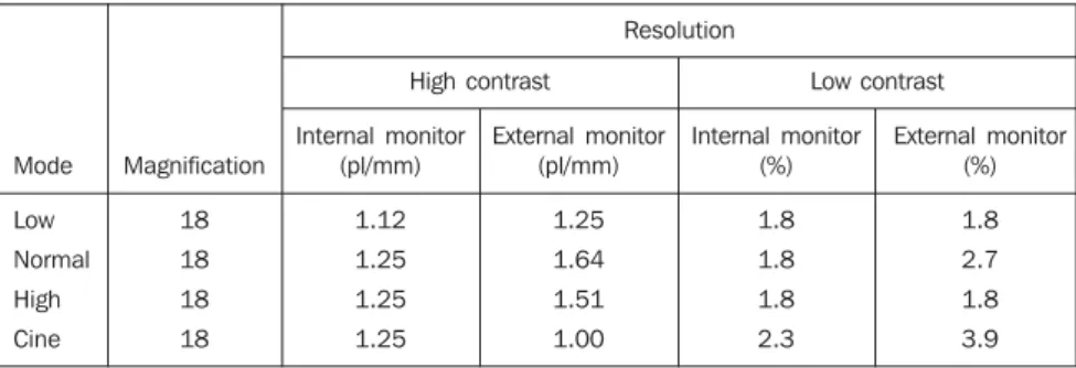
Table 2 Result of tests to evaluate high- and low-contrast resolution.
Resolution
High contrast Low contrast
Mode Low Normal High Cine Magnification 18 18 18 18 Internal monitor (pl/mm) 1.12 1.25 1.25 1.25 External monitor (pl/mm) 1.25 1.64 1.51 1.00 Internal monitor (%) 1.8 1.8 1.8 2.3 External monitor (%) 1.8 2.7 1.8 3.9
ventional radiology procedures performed in hemodynamics services, a high-contrast resolution is necessary to identify arteries, veins and lesions to be investigated, mainly for coronary procedures where the inves-tigated and treated structures present low caliber. The Order (Portaria) 453/98(4)
rec-ommends a high-contrast resolution value expressed in lp/mm > 1.4 lp/mm for the 15– 18 cm magnification mode, and = 1.0 lp/ mm for the 23–25 cm magnification mode. However, the values found in this test, on the internal hemodynamics room monitor, resulted lower than the recommended ones. This suggests that there may be anatomical details of difficult visualization on images observed on the monitor screen, inducing the physician to submit the patient to longer exposure times for acquisition of a higher number of images.
On Tables 1 and 2, it is possible to ob-serve that, in spite of the skin entrance air kerma rate being higher in the normal mode than in the high mode, there was no im-provement in the image quality (high- and low-contrast resolutions) on the internal monitor.
For low-contrast, a resolution between 1% and 4% is recommended(1,4–7). The
val-ues found by the present study present an acceptable low-contrast resolution, accord-ing to Table 2.
Generally, the external monitor pre-sented a higher quality than the internal one. It is important to note that the image quality is strictly related to the final medi-cal-diagnostic objective of the procedure. In the distortion test, the evaluated monitor presented 5.1% distortion, lower than the 10% value recommended by the Leeds test objects manual(7). The results of
the measurements are shown on Table 3, and calculations were made for the main di-agonal, and with the squares of the left upper and right lower corners, employing the equation 1.
Table 3 Dimensions measured during test for evaluating the image distortion degree.
Localization of the square
Left lower corner Left upper corner Central
Right lower corner Right upper corner Main diagonal Secondary diagonal
Diagonal (cm)
Half-value layer
Values found in the HVL evaluation are shown on Table 4. The value resulting from the HVL calculated by means of equation 2 was 2.0 ± 0.1 mmAl, for a 50 kV volt-age, with a reference value of 1.7 mmAl(4). For this value of HVL and voltage, the to-tal filtration of this equipment resulted in 3.5 mmAl(8). The useful beam HVL value should not be lower than 2.5 mmAl.
CONCLUSIONS
The results of the present study regard-ing dosimetric measurements (skin en-trance and image intensifier input air kerma rates) demonstrated the relevance of a pe-riodical evaluation by means of quality control tests, allowing the monitoring of the equipment performance, detection of anomalies or operational problems, as well as an estimation of workers and patients radiation exposure levels.
In the same way, the results regarding images quality suggest the necessity of a review of the images acquisition system of the fluoroscopic equipment. The periodical testing provides concrete data which can lead to an improvement in the image qual-ity, since these data allow the identification
Table 4 Results of the measurements performed for determining half-value layer.
Thickness (mmAl)
0 2 3 5
Reading (mGy/min)
11.1 ± 0.6 5.6 ± 0.3 4.2 ± 0.2 2.5 ± 0.1
of possible degradation of the imaging sys-tem along time. This evaluation is particu-larly significant on the monitor screen lo-calized inside the examination room, which is indispensable for the dynamic and real-time follow-up of the procedure.
The quality control is a tool in the imple-mentation of radiological protection mea-sures for every individual involved in interventional procedures, as well as other measures associated with prioritary aspects of equipment maintenance and achieve-ment of an image quality sufficient to reach the required diagnostic results.
The physicist-physician interaction with the medical professionals is essential for him to interpret his necessities allowing a safe work and accurate diagnosis. The con-sciousness of physicians and technicians on this aspect is extremely important, as well as an adequate training of every
pro-fessional involved in interventional radiol-ogy procedures.
This is part of the work developed by the physicist-physician of the service, who must effectively participate in the specialists staff of a hospital, according to requirements of the Brazilian legislation and good practices recommendations associated with radiation.
REFERENCES
1. International Commission on Radiological Pro-tection. Avoidance of radiation injuries from medical interventional procedures. ICRP Publi-cation 85. Oxford: Pergamon Press, 2000. 2. Williams JR. The interdependence of staff and
pa-tient doses in interventional radiology. Br J Radiol 1997;70:498–503.
3. Faulkner K. Radiation protection in interventional radiology. Br J Radiol 1997;70:325–326. 4. Brasil. Ministério da Saúde. Diretrizes de
prote-ção radiológica em radiodiagnóstico médico e odontológico. Portaria nº 453. Brasília: Diário oficial da União, 1/6/1998.
5. Brasil. Agência Nacional de Vigilância Sanitária. Guia de procedimentos para segurança e quali-dade de imagem em radiodiagnóstico médico. Resolução nº 64, de 4 de abril de 2003. 6. Products of fluoroscopy. 2004 [cited 2004 Feb
21]. Available from: www.leedstestobjects.com 7. Cowen AR, Clarke OF, Coleman NJ, Craven DM,
McArdle S, Hay GA. Leed x-ray test objects – in-struction manual. Leeds LS1 3 EX, 1992. 8. International Commission on Radiological