Iron casting skin management in no-bake mould
– Effects of magnesium residual level and mould
coating
* Iulian Riposan
Male, born in 1948, Ph.D, Professor. Major research areas: lamellar, nodular, compacted/vermicular and coral graphite irons - processing and complex characterization; austempered casting irons with LG, NG, CG or coral graphite; cast iron matrix composite; new modifying techniques for cast irons; cupola and electric furnaces operations.
E-mail: [email protected]
Received: 2014-08-20; Accepted: 2015-02-10
Mihai Chisamera, Nicoleta Ivan, *Iulian Riposan, Stelian Stan
POLITEHNICA University of Bucharest, Bucharest, Romania
F
uran resin-acid and phenolic resin-acid no-bake systems are very popular in ductile iron foundries because the mould strength contributes to fewer contraction defects during solidification (shrinkage and micro-shrinkage). With these moulds, only the contraction of the cooling liquid iron needs to be compensated for, hence, fewer and smaller risers can be employed, or even riserless designs can be considered (> 2.0 cm cooling modulus) [1] .Abstract:
The relative performance of coatings for furan resin sand moulds [P-toluol sulphonic acid (PTSA) as hardener] [FRS-PTSA moulds], was compared by analyzing the surface layer for degenerated graphite in Mg treated iron with 0.020wt.% to 0.054wt.% Mgres. It was found that the iron nodularising potential (Mg, Ce,La content) and whether the mould coatings contained S, or were capable of desulphurizing were important factors. These moulds have S in the PTSA binder, which aggravates graphite degeneration in the surface layer, depending strongly on the Mgres with lower Mgres increasing the layer thickness.
The application of a mould coating strongly inluenced graphite deterioration in the surface layer of castings.
It either promoted graphite degeneration to less compact morphologies when using S-bearing coatings, or conversely, limited the surface layer thickness using desulphurization type coatings. Independently of the S-source at the metal – mould interface, the presence of sulphur had an adverse effect on graphite quality at the surface of Mg-treated irons, but its negative effect could also reach the graphite phase within the casting section. If the coatings employed desulphurization materials, such as MgO, or a mixture (CaO + MgO + Talc) or Mg-bearing FeSi, they protected the graphite shape, improving graphite nodularity, at the metal – mould interface,
and so decreased the average layer thickness in FRS-PTSA moulds. FeSiMg was highly eficient in minimizing
the casting skin by improving graphite nodularity. It is presumed that the MgO or (MgO + CaO + Talc) based coatings acted to remove any S released by the mould media. The Mg-FeSi coatings also reacted with S from
the mould but additionally supplemented the Mg nodularising potential prior to solidiication. This dual activity is achievable with coatings containing active magnesium derived from ine Mg-FeSi materials.
Key words:
ductile iron; compacted graphite iron; surface layer; graphite degeneration; resin bonded sand mould; Mg-bearing mould coating; S-bearing mould coatingCLC numbers: TG221+.1 Document code: A Article ID: 1672-6421(2015)03-222-09
Fig. 1: Graphite degeneration in the surface layer of Mg-treated iron castings [no-bake mould]
Although resin mould technology is suitable and popular for ductile iron casting, it frequently contributes to graphite degeneration at the surface of spheroidal graphite cast iron, by forming a flake (lamellar) graphite skin. The sulphur contribution from the furan resin sand (FRS) - P-toluol sulphonic acid (PTSA) binder system originates in this PTSA component and has been identiied as a primary factor causing graphite degeneration at the metal-mould interface [2]. Some studies have suggested that graphite degeneration is caused at the surface by SO2 from the combustion of PTSA in the resin bonded sand at casting temperatures. SO2 is absorbed at the metal surface where it dissociates into atoms, allowing diffusion into the molten metal to form sulphides of the reactive elements: Mg, rare earth (RE) and Mn.[3]
The most important factors to obtain less than 0.15wt.% S in the mould, or even less than 0.07wt.% S, to decrease the depth of the surface layer are as follows: lower the PTSA addition, ideally to less than 50wt.% of the resin; avoid marginal noduliser additions (residual, active Mg), but usually not sufficient to eliminate the defect; lower pouring temperature, usually less than 1,350 °C (2,462 F) (depending on cast weight and section thicknesses); better maintenance and calibration of mixers; lower reclaimed sand rate, usually less than 70wt.%; use effective size classification in reclaimed sand system; phosphoric acid as a blend with PTSA, but introducing the risk of P pick-up; a mould coating with a CaO/MgO/Talc composition, capable of desulphurizing; high density protective mould coatings to preserve surface inish, but they are not as effective at minimizing S pick-up from the mould [2-9].
Various alternative coatings have been tested to determine whether surface deterioration can be prevented using a speciic mould coating. These include conventional graphite based coatings, inorganic materials expected to act as desulphurisers (Al2O3, CaCO3, Basic slag, CaF2 and Talc), and sinterable
materials expected to act as a barrier layer [2-9] .
By using CaO coatings capable of a desulphurizing reaction with SO2, the extent of the surface layer structure problem has been significantly reduced. Experience also suggests that the problem may be minimized through the use of a CaO or MgO wash on no-bake moulds [2,8,10] . Employing a coating based on a CaO/MgO/Talc composition is regarded to be particularly effective [6] .
The objective of this paper is to review the factors inluencing the formation of degenerated graphite layers at the surface of Mg treated, no-bake mould iron castings, using selected data from literature [2-10], and some of the previous papers by the present authors [11-16] with additional unpublished data.
1 Experimental procedure
Tables 1 and 2 show the characteristics of three experimental programs, while Table 3 displays the coating materials used [15,16]. The base iron in the experimental programs I and II was produced in a coreless induction furnace (100 kg, 2,400 Hz, 100 kW) with acid lining, and in the third program (III), a graphite crucible induction furnace (10 kg, 8,000 Hz) was used.
The melts were superheated to 1,550 °C (2,822 F) and held for 8 minutes before tapping into a pre-heated tundish type magnesium treatment ladle at 1,530 °C (2,786 F). FeSiCaMgRE alloy was used at different addition levels, to obtain different residual magnesium, cerium and lanthanum levels in the inal iron (Tables 1, 2). Treated irons were inoculated in all cases during transfer of Mg-treated iron to the pouring ladle with 0.5wt.% Ca,Ce,S,O-FeSi alloy [17].
A furan resin (3.0wt.%) – P-toluol sulphonic acid (PTSA) (6.53wt.% S content and 1.5wt.% addition) bonded silica sand (95.5wt.%) [FRS-PTSA] moulding system was used (Fig. 2). No
Table 1: Chemical composition of treated alloys
Alloy System Chemical composition (wt.%) Addition
Si Al Ca Mg RE Fe (wt.%)
Noduliser FeSiCaMgRE 46.0 0.80 1.20 6.05 0.96 Bal. 1.0 – 2.0 Inoculant Ca,Ce,S,O-FeSi* 70-76 0.75-1.25 0.75-1.25 - 1.5-2.0 [Ce] Bal. 0.5
reclaimed mould material was used and the moulds contained approx. 0.1wt.% S. The typical thermo-physical properties of these moulds include: 1,306 W·s1/2·(m2·K)-1 thermal diffusivity, 1,170 J·(kg·K) -1 specific heat, 0.94 W·(m·K)-1 thermal conductivity and 1,550 kg·m-3 density. Each mould included four identical semi-cylindrical samples [0.56 kg, cooling modulus CM = 0.71 cm] [Fig. 2(a, b)]. The half cylinder had a radius of 28 mm, but a radius of 17 mm was also incorporated at the ends of the diameter to avoid the sharp angles of a perfect half cylinder, which could have an end effect.
Different coatings (Table 3) were applied on the concave
surface of the semi-cylindrical sample moulds [see Fig. 2(a)]. All of the coatings were prepared in identical conditions, using fine sized materials up to 0.01 mm grain size, with the same binder type (expanded polystyrene – toluene), and were applied to the mould surface using the same procedures (0.35 – 0.40 mm coating thickness).
A S-bearing coating with intentionally added FeS2 powder (49wt.%–52wt.% S) was used to provide a supplementary source of sulphur at the metal – mould interface for the FRS-PTSA mould. Two coatings, based on MgO or a mixture (CaO + MgO + Talc), were expected to act as a desulphurizing layer, Table 2: Chemical composition of experimental ductile irons
*Other elements [wt.%): 0.017-0.046 P, 0.039-0.051 Cr, 0.033-0.047 Cu, 0.07-0.08 Ni, 0.0028-0.0087 Mo, 0.008-0.013 V, 0.0019-0.0043 W, 0.0031-0.0036 Sn, 0.0021-0.0036 As, 0.00045-0.0011 Pb, 0.0005-0.0009 Bi, 0.0021-0.0053 N
Program Ductile iron chemistry* (wt.%) Carbon
C Si Mn S Mg Ce La Al Ti equivalent CE (%)
1.1 3.06 2.76 0.15 0.018 0.021 0.0062 0.0022 0.012 0.008 3.90 I 1.2 3.23 2.54 0.18 0.019 0.027 0.0082 0.0033 0.012 0.007 3.99 1.3 3.15 2.54 0.17 0.015 0.054 0.0106 0.0050 0.015 0.006 3.92 II 2 3.39 2.11 0.089 0.0023 0.030 0.0075 0.0034 0.011 0.005 4.04 III 3 3.56 2.61 0.051 0.0018 0.036 0.0080 0.0040 0.013 0.007 4.36
Table 3: Coating materials
(1) Talc (wt.%): 33CaO, 14MgO, 28SiO2, 2Fe2O3; 1.0wt.% humidity; 25wt.% loss on ignition at 1,000 °C;
(2) FeSiCaMgRE alloy used for Mg-treatment to obtain ductile iron [Table 1];
(3) Binder: expanded polystyrene - toluene solution (30 wt.% polystyrene): 0.612 g·cm-3
density and 1,100 cP at 20 °C, viscosity;
(4) Expanded polystyrene (EPS) [0.0167 g·cm-3
density; Tt = 240 °C melting point];
(5) Toluene [0.8669 g·mL-1
density; -950 °C melting point; 110.60 °C boiling point; 0.590 cP at 20 °C, viscosity].
Materials*
Active materials Binder3
S [FeS2] 0.25 g FeS2 4.0 g Polystyrene4
10 mL Toluene5
MgO 0.25 g MgO 4.0 g Polystyrene 10 mL Toluene
1.3 g MgO
CaO+MgO+Talc 1.3 g CaO
0.3 g Talc1
FeSiCaMgRE 1.0 g FeSiCaMgRE2
4.0 g Polystyrene 10 mL Toluene
Mg+FeSi75 0.55 g Mg (ilings)
0.40 g FeSi75
Fig. 2: Experimental set including semi-cylindrical samples layout in resin sand mould (a), sample sizes (b) and cut sample for structural analysis (c) [all sizes are in mm]
4.0 g Polystyrene 10 mL Toluene
4.0 g Polystyrene 10 mL Toluene
(a) (b) (c)
Coating type Experimental
and were found to limit surface graphite degeneration in heavy section ductile iron produced in a furan resin–PTSA moulding system [6].
Two other coatings were designed to provide supplementary nodularising potential at the casting surface, by incorporating Mg and RE either as metallic Mg /or alloy nodularising elements into the coating mix. One coating used fine sized FeSiCaMgRE alloy based on the noduliser in these experiments, and another included Mg powder, as Mg ilings, mixed with ine sized FeSi75.
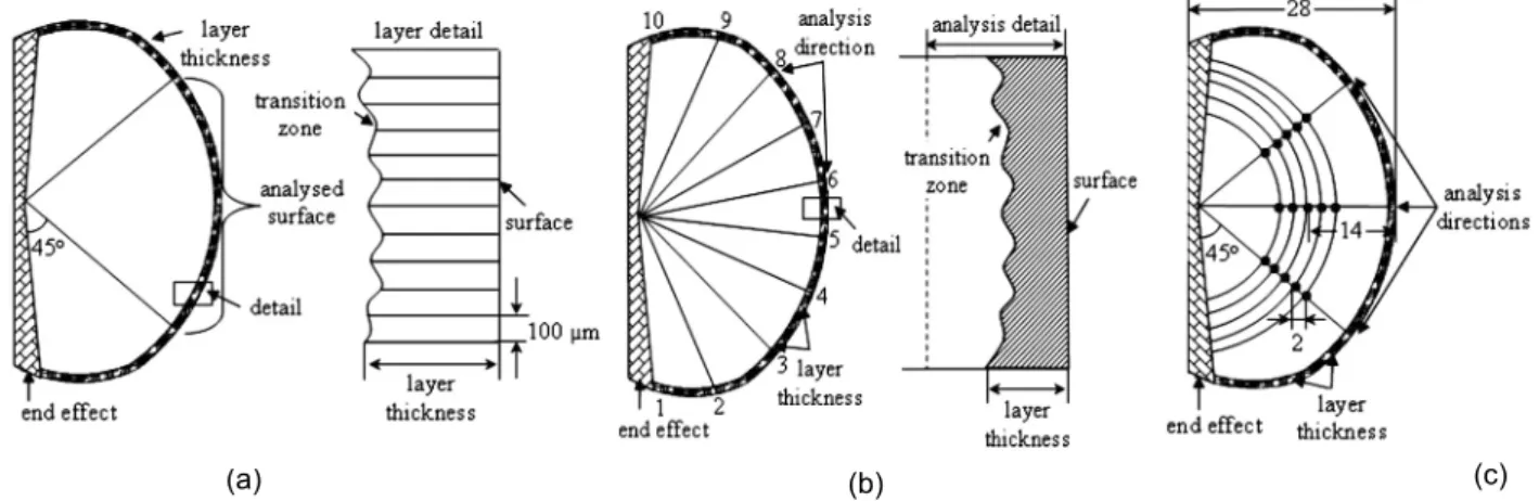
The samples were cut [Fig. 2(c)], and prepared for metallographic analysis using standard laboratory techniques. The thickness of the surface layer was evaluated, according to the schematic in Fig. 3(a), along the 30 mm total length, applying a 100 mm interval between each measurement. The measured thickness of the surface layer was expressed as an average of 300 observations. The structure in the surface layer was analyzed according to the schematic in Fig. 3(b), along 10 individual analysis directions (a total area of 800 mm2), and in the sample centre [Fig. 3(c)], along 3 directions, each one at 5 positions, 2 mm apart; the average level of the structure parameters was calculated. The variation in sample structures was evaluated on 3 radii in the section [similar to the schematic Fig. 3(c)], up to the centre of the samples, with 1.0 mm separating the analyzed points.
Structure analyses were performed using an Automatic Image
Analyzer [analySIS® FIVE Digital Imaging Solutions software], with the principal focus of characterizing the graphite particles, using the following parameters, according to the Fig. 4 images [ISO 16112 / 2005]:
Graphite Nodularity (NG) =
100 [Σ Anodules + 0.5 + Σ Aintermediates] / Σ Aall particles (1)
Roundness Shape Factor (RSF) = 4AG / pLG 2
(2)
where,
Anodules – Area of particles classiied as nodules;
Aintermediates – Area of particles classiied as intermediates; Aall particles – Area of all graphite particles, greater than 10 mm; AG – Area of the graphite particle in question;
LG – Maximum axis length of the graphite particle in question.
The graphite nodules were deined by using the ISO 16112 / 2005 statement, that is, “the nodules which have the Roundness Shape Factor RSF = 0.625–1.0” (Fig. 4). The intermediate particles were deined by RSF = 0.525–0.625; RSF < 0.525 refers to compacted graphite, at higher degree of compaction (RSF = 0.425–0.525), and lower degree of compaction, typically for RSF < 0.425. Flake graphite particles and graphite particles with maximum axis length less than 10 mm were not included.
Fig. 3: Analysis procedure to evaluate the surface layer thickness: (a) and structure parameters in the surface layer (b) and sample center (c)
Fig. 4: Visual representation of graphite particles categorized by Roundness Shape Factor (RSF) [ISO/FDIS 16112:2005] [RSF =0.625 to 1.0, ISO 945 Form VI, nodules; RSF = 0.525 – 0.625, ISO 945 Forms IV and V, intermediates; RSF < 0.525, ISO 945 Form III, compacted graphite]
2 Results and discussion
For the same base chemistry (carbon equivalent CE = 3.9%–4.0%), three experimental heats (1.1 – 1.3, Table 2) in the first experimental program [I] are differentiated by the level of residual magnesium, cerium and lanthanum contents [Fig. 5(a)], which were intentionally varied in a wide range [0.021wt.% – 0.054wt.% Mg, 0.0062wt.% – 0.0106wt.% Ce, 0.0022wt.% – 0.0050wt.% La], in order to obtain different graphite morphologies, such as compacted graphite and spheroidal graphite, with different ratios between them.
The content of trace elements is at a low level, according to normal ductile iron production practice. There is practically no difference in the content of trace elements in the three heats. The cumulative inluence of the chemical composition of the Mg-treated irons as they affect pearlite content (factor Px, Equation 3) and anti-nodularising effect (factor K, Equation 4), according to Thielman’s factors [18] are included in Fig. 5(b). It could be
concluded that the content of anti-nodularising elements in Mg-treated irons is suficiently low (K = 0.4), that the role of rare earth elements to counteract these elements is not necessary. On the other hand, the pearlite factor Px = 0.2 – 0.5 at very low level indicates a ferrite forming tendency, for conventional solidiication conditions.
Px = 3.0 (%Mn) – 2.65 (%Si - 2.0) + 7.75 (%Cu) + 90 (%Sn) + 357 (%Pb) + 333(%Bi) + 20.1 (%As)+ 9.60 (%Cr) + 71.7 (%Sb) (3) K = 4.4 (%Ti) + 2.0 (%As) + 2.4 (%Sn) + 5.0 (%Sb) + 290 (%Pb) + 370 (%Bi) + 1.6 (%Al) (4)
Fig. 5: Residual Mg and rare earth [RE] (a) and pearlite (Px) and antinodularising (K)
Thielman’s factors (b) of experimental Mg-treated irons [Programs I, II and III, Table 2]
The samples solidiied in moulds with sulphur present from the PTSA part of the furan resin sand - P-toluol sulphonic acid (PTSA) [FRS-PTSA]. The iron structure in the cast surface layer with no mould coating was analyzed as the reference condition. Additionally, other coatings with the possible effects from an intentional S-[FeS2] addition to the coating or, conversely, a desulphurization type [MgO] coating were evaluated. The graphs and images included in Figs. 6 and 7 demonstrate the influence of nodularising potential [Mgres] and the various coating applications.
Sulphur incorporated in the FRS-PTSA moulds evidently promoted graphite degeneration in the surface layer of the Mg-treated irons test castings in the prevailing solidification conditions, depending on the residual magnesium content and coating type.
At lower magnesium content, less than 0.03wt.% Mgres, typical of compacted graphite cast irons, there was greater graphite degeneration in the cast surface layer in uncoated moulds (Fig. 6), compared to the higher magnesium content, 0.054wt.% Mgres, typical of ductile irons (280-530 mm thickness vs. 185 mm in ductile iron).
It is assumed that SO2 will result from the combustion of PTSA in the resin bonded sand at the casting temperature. SO2 is absorbed at the metal surface after it has dissociated into atoms, which allows diffusion into the molten metal, and/or will be reduced by iron to form dissolved FeS and FeO. Both these products will react with magnesium in solution in the iron melt. As a consequence of the localized, elevated sulphur levels, magnesium is partially consumed prior to solidiication, and the
nodulising potential of the treated iron decreases.
By intentionally incorporating sulphur in the coating material, the graphite morphology in the surface layer deteriorated more, with the thickness of the abnormal surface layer increasing by up to 50%. The behaviour of this coating with added sulphur was a further endorsement of the role of sulphur already in the binder system as PTSA. It is assumed that sulphur supplied by FeS2 in the intentionally added coating complemented sulphur already available in the mould from the PTSA, and diffused into the outer sample layer to react with Mg in solution in the molten iron within the mould cavity. As a consequence of the localized, elevated sulphur levels, magnesium is partially consumed prior to solidification, and the nodularising potential of the treated iron is decreased at the mould surface.
Coatings based on desulphurizer type materials, such as MgO, provided some protection at the metal – mould interface against graphite degeneration, with a decrease in the average layer thickness compared to the reference (uncoated moulds),
{SO2} + 3[Fe] = [FeS] + 2[FeO] (6)
[Mg] + [FeS] = (MgS) + [Fe] (7)
[Mg] + [FeO] = (MgO) + [Fe] (8) CH3C6H4SO3H [PTSA] + HOH [water steam]
= C6H5CH3 [Toluene] + H2SO4
Fig. 6: Inluence of residual magnesium content and coating type on the surface layer thickness and structure of
Mg-treated iron castings [average layer thickness and un-etched irons [Program I]
with residual magnesium content as a strong factor: 10%-30% decrease of the layer for 0.020wt.%-0.027wt.% Mgres and more than a seven times decrease for 0.054wt.% Mgres, respectively. It is assumed that the application of this coating developed a local desulphurizing environment, thereby reducing the negative effect of sulphur released by the mould. Its effectiveness is more signiicant for higher magnesium content in ductile iron, but limited at the lower magnesium content commonly used for compacted graphite irons.
Residual magnesium levels and coating conditions also affect graphite phase characteristics in the tested casting central area
(Figs. 7 and 8). Lower residual magnesium content not only led to decreased graphite nodularity within the casting section but also to an increased thickness of the abnormal surface layer. The two characteristics have a close relationship. With increasing thickness of the surface layer, the graphite nodularity also decreased in the casting centre (Fig. 7).
desulphurize, beneficial effects were observed for graphite shape throughout the section: reduced thickness of the abnormal surface layer and higher graphite nodularity in the centre. This behaviour could be interpreted as a demonstration that sulphur diffuses into molten iron, where it can react with gaseous magnesium inside a liquid iron volume.
A similar behaviour was found in previous tests by adding sulphur as FeS2, in the treatment ladle, after Mg-treatment, to obtain a compacted graphite cast iron. A limited sulphur addition (0.002wt.%
- 0.02wt.% S) transformed nodular + vermicular graphite irons, or nodular graphite irons, (0.025wt.-0.04wt.% Mg) to compacted/vermicular graphite cast irons, with a controlled structure (>80% compacted graphite) in high volume foundry conditions [19-24].
Since it was established that a coating applied at the metal-mould interface with a desulphurizing capability is so important for preserving the quality of the cast surface layer as well as the graphite characteristics over the entire sample section, more complex experiments were recorded (Programs II and III) (Fig. 8):
(a) A ductile iron at marginal nodularising potential ( P r o g r a m I I , 0 . 0 3 0 w t . % M gr e s, 0 . 0 0 7 5 w t . % C er e s, 0.0034wt.%Lares), to encourage greater sensitivity to such phenomena, and
(b) A ductile iron at normal nodularising potential ( P r o g r a m I I I , 0 . 0 3 6 w t . % M gr e s, 0 . 0 0 8 w t . % C er e s, 0.004wt.%Lares), both of them solidiied in resin bonded sand – PTSA moulds (binder with sulphur content).
The castings from programs II and III heats were also characterized by lower antinodularising inluencing factor (K = 0.38-0.54) and pearlite promoting factor (Px= 0.38-0.70). Different coating systems were considered, such as the
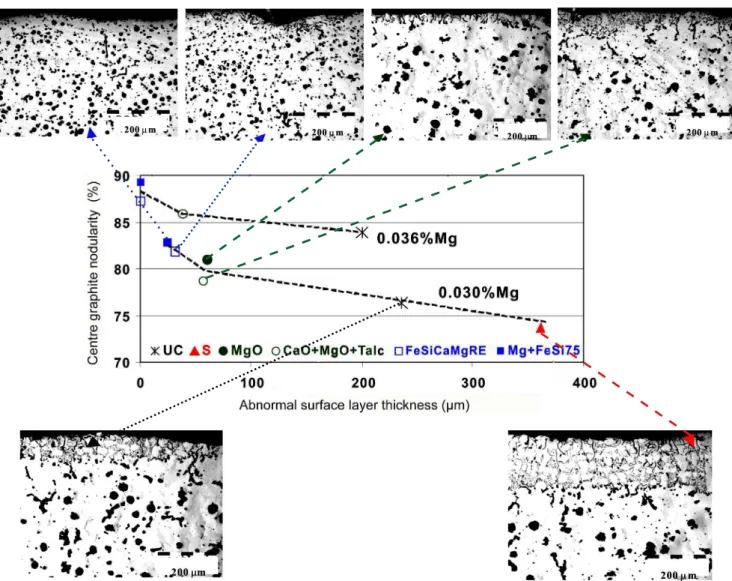
Fig. 8: Inluence of desulphurization type coating on degenerated graphite surface layer thickness and structure, and
castings centre graphite nodularity [Programs II and III] Fig. 7: Relationship between graphite nodularity in casting
previously used MgO and (CaO + MgO + Talc) coatings [6,8,10]. Additionally some materials with active Mg (FeSiCaMgRE or Mg + FeSi75), were recently tested by the current authors [11,13,15,16]. Some representative results relecting the thickness of the
degenerated graphite surface layer and its structure, and graphite nodularity in the centre of the test samples are included in Fig. 8.
It was re-conirmed (see Figs. 6 and 7) that a sulphur bearing coating increases the surface layer thickness (more than 50%), while a MgO bearing coating decreases this thickness (by more than a third), for ductile iron with a marginal nodularizing potential (Program. II, Table II).
A S-bearing coating also reduced graphite nodularity in the casting centre, whereas the nodularity was improved with a coating containing MgO. The more complex desulphurization coating (CaO + MgO + Talc) shows slightly more protection against graphite degeneration at the casting surface.
The best results, for both lowering the surface layer thickness and increasing the graphite nodularity in the casting centre, were obtained when coatings incorporated active Mg, either as a ine size FeSiCaMgRE alloy (same as the nodulizer) or as a mechanical mixture of Mg in a ine size FeSi75 alloy (Fig. 8).
It is assumed that the oxide type coating [MgO or (CaO + MgO + Talc)] acted mainly to neutralize sulphur migrating from the mould in a desulphurizing reaction, whereas the Mg-FeSi coatings performed a complementary role beyond desulphurization with supplementary magnesium regenerating the nodularising potential prior to solidification. The coatings with active Mg within the mix create a late source of nodularising element at the casting surface, to counteract losses due to reactions with either sulphur or oxygen at this interface. This speciic effect is important in the solidiication of heavy castings for the surface layer quality, but also has beneits in the higher volume production of much smaller castings.
The specific effects of desulphurization coatings, based on CaO, MgO or FeSiMg agents are practically the same for the two ductile irons considering their nodularising potential, which is marginal (0.030wt.% Mgres,) in Program II and normal (0.036wt.% Mgres) in Program III. A higher residual magnesium leads to a reduced thickness of the abnormal surface layer with higher graphite nodularity, including at the casting centre (Fig. 8). A general view of all the results obtained for the inluence of the mould coating type, at different magnesium residuals, on the thickness of the abnormal surface layer and graphite nodularity in the casting centre [0.71 cm cooling modulus], solidiied in no-bake, furan resin bonded sand moulds [P-Toluol Sulphonic Acid (PTSA) as hardener] [FRS-PTSA], is shown in Fig. 6.
The results illustrate not only the sensitivity of this type of mould to graphite degeneration at the metal-mould interface, but demonstrate the dangers of any sulphur source at this interface and the beneits of desulphurization type coatings (MgO or CaO + MgO + Talc) to limit this defect or even eliminate it if the coatings incorporate active Mg. All of these desulphurization type coatings also contributed to higher graphite nodularity in the casting centre. There was reduced surface layer thickness, with higher graphite nodularity over the entire casting section.
It has been shown that the degenerate graphite surface layer is mainly attributable to a metal-mould chemical interaction, especially where sulphur is available. There are further beneits if a desulphurisation capability can be combined with a source of magnesium for an effective coating offering overall protection. This dual function supports the application of basic coatings containing active magnesium, derived from Mg–FeSi materials.
3 Summary
The relative performance of coatings (S-bearing coating and desulphurization potential coatings) for furan resin bonded sand moulds [P-toluol sulphonic acid (PTSA) as hardener] [FRS-PTSA] was evaluated by analyzing the degenerate graphite surface layer in Mg treated iron with 0.020wt.% to 0.054wt.% Mgres in the tested castings (0.71 cm cooling modulus), and determining the graphite characteristics up to the casting centre.
Based on this work, the following main conclusions can be drawn, referring to the experimental solidiication conditions:
(1) It was reconfirmed that for the furan resin – PTSA moulding system, sulphur delivered by the mould is an important contributor to graphite degeneration in the surface layer of Mg treated iron castings.
(2) It was found that the iron nodularising potential, based on Mg, Ce and La contents, and the mould coatings with sulphur content, or conversely with a desulphurization capability, are important factors for graphite degeneration in the surface layer of castings, in these test conditions.
(3) Uncoated FRS-PTSA moulds, which have sulphur in the binder, promoted graphite degeneration in the surface layer of the test castings, with the thickness of this layer increasing as residual magnesium content decreased: compacted graphite iron is more sensitive compared to nodular graphite iron, and similarly, a ductile iron with a marginal nodularising potential is characterized by a greater thickness of abnormal surface layer than a ductile iron at normal nodularising potential for the speciic solidiication conditions.
(4) The application of a mould coating strongly influenced graphite deterioration in the surface layer of castings, either driving graphite degeneration further to less compact morphologies, when using S-bearing coatings, or conversely, limiting the graphite degeneration to a narrower surface layer when desulphurization type coatings were employed.
(5) Independently of whether the sulphur source at the metal-mould interface is from the metal-mould or a coating, the presence of sulphur had an adverse effect on graphite quality at the surface of compacted graphite iron or ductile iron, but, for these test conditions, it could also influence the quality of the graphite phase within the section and up to the centre of the castings. It is assumed that sulphur supplied from that intentionally added to a coating complemented the sulphur available in the mould, from the PTSA, and diffused into the outer sample layer to react with Mg treated iron within the mould cavity.
such as MgO, or a mixture (CaO + MgO + Talc) or active Mg-bearing FeSi, they protected the graphite at the metal–mould interface, decreasing the average layer thickness in FRS-PTSA moulds and increasing graphite nodularity over the casting section. In this study, FeSiMg alloy was very eficient, while the mechanical mixture of metallic Mg with a FeSi75 alloy appears to be more effective than a FeSiCaMgRE alloy.
(7) It is presumed that the MgO or (MgO + CaO + Talc) based coatings acted locally to remove or capture any sulphur released by the moulding system. The coating mixes with Mg-FeSi, derived from nodulizer materials, had an additional role to desulphurization by providing supplementary active Mg to raise the nodularising potential prior to solidiication.
(8) The graphite characteristics in the centre of the samples, mainly as nodularity, evolved in a clear relationship with the changes in the degenerated graphite surface layer, for the prevailing solidiication conditions.
(9) Based on technical literature and appropriate experiments, the following policies are recommended for FRS- PTSA moulding lines, to control the abnormal surface layer formation: ♦ The sulphur content should be less than 0.15wt.% in the mould (or even < 0.07wt.% S);
♦ Reduce the PTSA content, ideally to less than 50wt.% of the resin;
♦ Reduce reclaimed sand usage, usually less than 70wt.%; ♦ Use well maintained and calibrated mixers;
♦ Use effective size classiication in reclaimed sand systems; ♦ Blend phosphoric acid with the PTSA, but be aware this may lead to P pick-up;
♦ Increase the nodulizer addition (with attendant risk to the casting quality), and this usually will not eliminate the defects;
♦ Lower the pouring temperature, usually less than 1,350 o
C/2,786 F (depending on casting weight and predominant section size);
♦ Use mould coatings with a desulphurization capability, such as a CaO/MgO/Talc composition and especially similar coatings with Mg-bearing FeSi in the mix.
References
[1] Ductile Iron Techniques, Suggestions for Ductile Iron Production. R.T.I.T Inc., Montreal, Canada, 1971.
[2] Riposan I, Chisamera M and Stan S. Control of Surface Graphite Degeneration in Ductile Iron for Windmill Applications. International
Journal of Metalcasting, 2013, 7(1): 9-20.
[3] H. Xiaogan, et al. Nodular iron surface deterioration due to PTSA in resin.
AFS Transactions, 1992, 100: 9-15.
[4] Riposan I, Chisamera M, Stan S, et al. Surface Graphite Degeneration
in Ductile Iron Castings for Resin Molds. In: Proc. of 8th International Symposium on ‘Science and Processing of Cast Iron’, Beijing, China, Oct.
2006, 110–115; Tsinghua Science and Technology Journal, 2008, 13(2): 157-163.
[5] Riposan I, Chisamera M and Stan S. Performance of heavy ductile iron castings for windmills. China Foundry, 2010, 7(2): 163-170.
[6] Baier J and Koppen M. Manual of casting defects. Incidence and
avoidance of defects attributable to molding sands. Marl, Germany, IKO-Erbsloh, 1994: 32–35.
[7] Golovan N A, Dudni K J A and Dubrov VV. Formation of lake graphite near the surface of nodular cast iron casting. Russian Casting Production
Journal, 1977(7): 35-36.
[8] Marti F and Karsay S I. Localized lake graphite structure as a result of a reaction between molten ductile iron and some components of the mold. AFS Transactions, 1979, 87: 221-226.
[9] Bauer W. Research on the surface graphite degeneration in the ductile iron casting in PTSA-furan resin molds. Giesserei – Praxis, 1982(11):
175-183.
[10] Morita S and Inoyama N. Behavior of nitrogen in cast iron. AFS Cast
Metals Research Journal, 1969, 5(3): 109.
[11] Ivan N, Chisamera M and Riposan I. Mg-bearing coating of resin sand
– PTSA moulds to control graphite degeneration in the surface layer of ductile iron castings. Materials Science and Technology, 2012, 28(11):
1246–1253.
[12] Ivan N, Chisamera M and Riposan I. Inluence of magnesium content and coating type on graphite degeneration in surface layer of iron castings in resin sand – PTSA moulds. ISIJ International, 2012, 52(10): 1848–1855.
[13] Ivan N, Chisamera M and Riposan I. Mold Coatings to Reduce Graphite Degeneration in the Surface Layer of Ductile Iron Castings. International
Journal of Metalcasting, 2012, 6(4): 61-69.
[14] Ivan N, Chisamera M and Riposan I. Graphite degeneration in the
surface layer of ductile iron castings. International Journal of Cast Metals Research, 2013, 26(3): 138-142.
[15] Ivan N, Chisamera M and Riposan I, et al. Control of Graphite Degeneration in the Surface Layer of Mg-treated Iron Castings in Resin
Sand ― P-Toluol Sulphonic Acid (PTSA) Molds. AFS Transactions, 2013, 121: 379-390.
[16] Ivan N. Research on the Graphite Degeneration Phenomenon in the Supericial Layer of the Iron Castings with Compact Graphite Forms. Ph.D Dissertation, POLITEHNICA University of Bucharest, Romania, 2011. [17] ULTRASEED®
Ce Inoculant–ELKEM Foundry Products Brochure, www.
foundry.elkem.com, April 2012.
[18] Thielman T. Zur Wirkung van Spurenelementen in Gusseisen mit
Kugelgraphit. Giessereitechnik, 1970(1): 16-24.
[19] Riposan I and Chisamera M. Herstellung von Gusseisen mit
Vermiculargraphit aus Magnesiumbehandeltem Gusseisen durch zusatz von Schwefel. Giesserei Praxis, 1991(9-10): 155-162; Casting, Forging
and Heat Treatment (Japan), 1993, 547: 17-23.
[20] Chisamera M and Riposan I. Sulphur Inoculation of Mg-treated Cast Iron
― An eficient way to control graphite morphology and nucleation ability. In: 5th Int. Symp. on the Physical Metallurgy of Cast Iron, Oct. 1994,
Nancy, France; Advanced Materials Research, Trans Tech. Publ., 1997(4-5): 293-300.
[21] Chisamera M, Riposan I and Barstow M. Sulfur Inoculation of Mg-treated Cast Iron-an efficient possibility to obtain Compacted Graphite
Cast Iron and to improve Graphite Nucleation ability in Ductile Iron. AFS Transactions, 1996, 104: 581-588.
[22] Chisamera M, Riposan I, Stan S, et al. The Importance of Sulfur to Control Graphite Nucleation in Cast Irons. AFS Cast Iron Inoculation Conference,
April 1998, Rosemont, Illinois, USA, Paper no. 3.
[23] Chisamera M, Riposan I, Stan S, et al. Experience Producing Compacted
Graphite Cast Irons by Sulfur Addition after Magnesium Treatment. AFS Transactions, 2002, 110: 851-860; Giesserei-Praxis, 2005(1): 31-37.
[24] Chisamera M, Riposan I, Stan S, et al. Magnesium – Sulfur Relationship in Ductile and Compacted Graphite Irons as Inluenced by Late Sulfur Additions. AFS Transactions, 2003, 111: 03-093.
![Fig. 1: Graphite degeneration in the surface layer of Mg-treated iron castings [no-bake mould]](https://thumb-eu.123doks.com/thumbv2/123dok_br/18390884.357538/2.892.79.821.119.303/fig-graphite-degeneration-surface-layer-treated-castings-mould.webp)
![Fig. 2: Experimental set including semi-cylindrical samples layout in resin sand mould (a), sample sizes (b) and cut sample for structural analysis (c) [all sizes are in mm]](https://thumb-eu.123doks.com/thumbv2/123dok_br/18390884.357538/3.892.176.712.362.567/experimental-including-cylindrical-samples-layout-sample-structural-analysis.webp)
![Fig. 5: Residual Mg and rare earth [RE] (a) and pearlite (P x ) and antinodularising (K)](https://thumb-eu.123doks.com/thumbv2/123dok_br/18390884.357538/5.892.84.790.353.550/fig-residual-mg-rare-earth-pearlite-p-antinodularising.webp)
![Fig. 6: Inluence of residual magnesium content and coating type on the surface layer thickness and structure of Mg- Mg-treated iron castings [average layer thickness and un-etched irons [Program I]](https://thumb-eu.123doks.com/thumbv2/123dok_br/18390884.357538/6.892.86.816.113.895/inluence-residual-magnesium-thickness-structure-castings-thickness-program.webp)