6SHFLILFDWLRQDQG'HVLJQRIDQ(WKHUQHW
,QWHUIDFH6RIW,3
0UpU2KUTGXJU,XGMUYU+J[GXJU)UYZG0[KXMKT8UINUR9KXMOU(GSVO8OIGXJU8KOY
;TO\KXYOJGJK,KJKXGRJU8OU-XGTJKJU9[R
/TYZOZ[ZUJK/TLUXSlZOIG
)GO^G6UYZGR)+6
6UXZU'RKMXK89¤(XGYOR
aLXGMUYUKIUYZGP[KXMKTHGSVOXKOYc&OTL[LXMYHX
Abstract
The IP (Intellectual Property) for Ethernet Interface is a hardware module designed to execute the MAC (media access control) service on the Ethernet standard. The goal of this IP module is to provide an easy way to develop new devices with connection to an Ethernet LAN (Local Area Network). The standard protocols used make this IP module reusable for different designs with an interface to Ethernet LANs. The Ethernet Interface IP is described and simulated in VHDLKeywords: Ethernet interface, local area network, design with VHDL, IP, VLSI design
1 Introduction
The computing scene today is dominated by the inter-connection of different devices, in a distributed architec-ture extending the communication possibilities. The ex-plosion of the Internet, the exponential use of the e-mail, and new services like videoconference, video on demand, etc, contribute for an increasing need for connectivity. A new set of low-end, low-cost devices, named internet appliances, will reach the market in the niche of home and office automation, all of them enabled with some sort of low-cost network connectivity, using wires and 10baseT connectors. Conventional ethernet speeds will suffice for those devices, while GigabitEthernet and 100baseT will be applied solely for computer intercon-nections and fast data links.
The concept of computer networks is extremely large. However, it is possible to differentiate generically the computer networks in accordance with its area of cover-age. Thus, Local Area Networks (LAN) are generally confined to a building or even a campus, Metropolitan
Area Networks (MAN) are restricted to campus, blocks or to urban perimeters of great cities and Wide Area Networks (WAN) connecting cities, countries and conti-nents.
com-munication needs. It is then compelling that each device to be connected to an Ethernet Local Area Network have an Ethernet Interface.
2 The CSMA/CD Access Method
The Carrier Sense Multiple Access with Collision Detection (CSMA/CD) media access method is the means by which two or more station/devices share a common transmission medium. In transmission mode, a station waits (defers) for a quiet period on the medium (that is, no other station is transmitting) and then it sends the intended message in a bit-serial form. If, after initiat-ing a transmission, the message collides with one from another station, then each transmitting station intention-ally sends a few additional bytes to ensure propagation of the collision throughout the system. The station remains silent for a random amount of time (back off) before attempting to start transmission again.
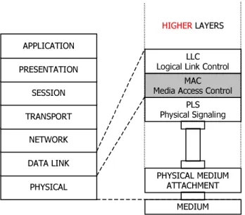
The CSMA/CD media access method is standardized by IEEE 802.3 [1][2] and it belongs to the MAC (media access service) sublayer. The MAC sublayer and the Logic Link Control sublayer together encompass the functionality intended for the Data Link layer as defined in the OSI Model. The physical layer and the Data Link layer standardized by IEEE 802.3 are intended to corre-spond closely to the lowest layers of the ISO Model for Open Systems Interconnection (see figure 1) [3].
3+<6,&$/ '$7$ /,1.
1(7:25. 75$163257
6(66,21 35(6(17$7,21
$33/,&$7,21
3/6 3K\VLFDO 6LJQDOLQJ
0$& 0HGLD $FFHVV &RQWURO
//& /RJLFDO /LQN &RQWURO
+,*+(5/$<(56
3+<6,&$/ 0(',80 $77$&+0(17
0(',80
Figure 1: IEEE LAN Standard relationship to OSI Reference Model.
The CSMA/CD media access method is the same method used in the Ethernet standard. However, there is a difference between the Ethernet standard and the IEEE 802.3 in the structure of their frames. In the Ethernet
frame there is a field called type and in the standard IEEE 802.3 the size of the frame is given in this field. But this difference does not cause problems to implement the IEEE 802.3 standard CSMA/CD method in an Ethernet Interface.
2.1 Ethernet Frame Structure
Figure 2 shows the seven fields of a frame: the pre-amble, Start Frame Delimiter (SFD), the addresses of the frame’s source and destination, a type field, the data to be transmitted and the Frame Check Sequence (FCS) con-taining a cyclic redundancy check value to detect errors in received frames. All these fields are fixed size except the Data, which may contain an integer number of octets.
The preamble field is a 7-octet(or 7-byte) field that is used to allow the PLS circuitry to reach its steady-state synchronization with the received frame timing. The start frame delimiter field is the sequence 10101011. It imme-diately follows the preamble pattern and indicates the start of a frame.
2FWHWV
2FWHW
2FWHWV
2FWHWV
2FWHWV
2FWHWV
Frame Transmitted/
Received Top-down
35($0%/(
6)' VWDUW IUDPH GHOLPLWHU
'HVWLQDWLRQ $GGUHVV
6RXUFH $GGUHVV
'DWD )UDPH 7\SH
)UDPH &KHFN 6HTXHQFH
Figure 2: Ethernet Frame Format
The frame check sequence field contains a 4-octet (32-bit) cyclic redundancy check (CRC) value. This value is computed as a function of the contents of source address, destination address, type and data.
An invalid Ethernet frame shall be defined as one that meets at least one of the following conditions:
(i) the frame does not have an integral number
of octets in length;
(ii) the bits of an incoming frame (exclusive of
the FCS field itself) do not generate a CRC value identical to the one received[4];
(iii) the frame length is shorter than the minimum
2.2 CSMA/CD Access Method Functional
Capabilities
The following summary shows a quick reference of the functional capabilities of CSMA/CD MAC sublayer.
In frame transmission:
• accept data from the LLC sublayer and construct
a frame;
• present a bit-serial data stream to the physical
layer for transmission on the medium.
In frame reception:
• receive a bit-serial data stream from the physical
layer
• present to the LLC sublayer frames
• defer transmission of a bit-serial stream
when-ever the physical medium is busy
• append proper FCS value to outgoing frames and
verify full octet boundary alignment
• checks incoming frames for transmission errors
by way of FCS and verifies octet boundary alignment
• delay transmission of frame bit stream for
speci-fied interframe gap period
• halt transmission when collision is detected
• schedule retransmission after a collision until a
specified retry limit is reached
• enforce collision to ensure propagation
through-out network by sending jam message
• discard received transmission that are less than a
minimum length
• append preamble, start frame delimiter and FCS
to all outgoing frames
• remove preamble, start frame delimiter and FCS
to all incoming frames
3 The Ethernet Interface IP
The Ethernet Interface IP is a hardware module de-sign to implement all CSMA/CD functional capabilities. However, the physical layer must be handled by an uni-versal transceiver. So, the physical layer interface speci-fication was designed using the LXT901A/907A Univer-sal Transceiver chip of Level One[5].
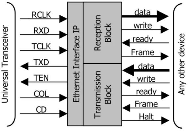
The LLC interface provides an easy way to transform data between Ethernet Interface and other devices. These devices can implement the LLC sublayer or can use the Ethernet Interface to enable their communication using Ethernet standard. Figure 3 shows the I/O of the Ethernet Interface IP. (W KH UQ HW ,QW HU ID FH ,3 5H FH SW LRQ %O RFN 7UD QVP LVVL RQ %O RFN 5&/. 5;' 7&/. 7;' 7(1 &2/ &' GDWD ZULWH UHDG\ )UDPH GDWD ZULWH UHDG\ )UDPH +DOW 8QL YH UVDO 7UD QV FH LYH U $Q\ RWK HU GH YL FH
Figure 3: The Interfaces of Ethernet Interface
The RCLK signal is a 10MHz clock used to synchro-nize the input bit-serial stream on the RXD. In the same way, the TCLK is a clock used to synchronize de output bit-serial stream on the TXD, but the TEN(Transmit Enable) must be used to enable the transceiver to transmit the outgoing bit-serial stream. The COL (collision detect) pin indicates when the collision occurs and the CD (car-rier detect) indicates when the medium is busy.
The Ethernet Interface was divided in two independ-ent blocks: transmission block and reception block. These blocks work concurrently, but the CD signal does not allow simultaneous transmission and reception.
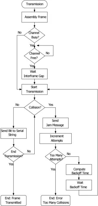
To allow all CSMA/CD functional capabilities, two algorithms were specified. The first one, shown in figure 4, implements the transmission tasks in the transmission block. The second one, shown in figure 5, performs the reception task in the reception block.
In the reception block, data is a 16-bit line output where the reception block will enable the frame data (destination address, source address, data) incoming from LAN. When a new word is ready on 16-bit line the write signal warns. If the frame line is equal to 1 then the data contains frame data. In other way, if the frame line is equal to 0 then data contains a validation word.
Con-versely, after an invalid frame reception, the reception block will send an invalidation word that contains the two most significant bits set to 0.
7UDQVPLVVLRQ
$VVHPEO\ )UDPH
6WDUW 7UDQVPLVVLRQ
&KDQQHO %XV\"
&KDQQHO )UHH"
:DLW ,QWHUIUDPH *DS
&ROOLVLRQ"
(QG 7UDQVPLVVLRQ"
6HQG -DP 0HVVDJH
,QFUHPHQW $WWHPSWV
7RR 0DQ\ $WWHPSWV"
&RPSXWH %DFNRII 7LPH
:DLW %DFNRII 7LPH (QG )UDPH
7UDQVPLWWHG
(QG (UURU 7RR 0DQ\ &ROOLVLRQV 1R
1R
1R
1R
1R
<HV <HV
<HV <HV
<HV
6HQG %LW WR 6HULDO 6WULQJ
Figure 4: Transmission Algorithm
The ready input line indicates when the 16-bit line is ready for new data. If a new data is coming and the data line is not ready (ready line equals to 1), the reception block will discard the entire incoming frame. Figure 6 shows the reception block interface protocol.
5HFHSWLRQ
6WDUW 5HFHSWLRQ
(QG 5HFHSWLRQ"
0LQLPXP /HQJWK"
)&6 2N"
'LVDVVHPEOH )UDPH
(QG )UDPH 5HFHLYHG
(QG )UDPH (UURU 1R
1R
1R <HV
<HV
<HV
5HMHFW )UDPH 6HULDO 6WULQJ5HDG %LW RI
Figure 5: Reception Algorithm
In the transmission block, data is a 16-bit line input where the devices connected to the Ethernet Interface will enable the frame data (destination address, source address, data) intended to the LAN.
'$7$ '$7$ 9DOLGDWLRQ
data
frame
write
ready
Figure 6: Reception Block Interface Protocol
The reception block works in a similar way, when a new word is ready in the 16-bit line the write signal warns. If the frame line is equal to 1 then the data con-tains frame data. If not, frame line equals to 0, then data contains the output frame length in number of octets.
con-trol the output bit-serial stream.
'$7$ '$7$ 9DOLGDWLRQ
data
frame
write
Halt ready
Figure 7: Transmission Block Interface Protocol
The ready signal indicates when the 16-bit line is ready for a new data (ready equal to 0). The ready will remain equal to 1 until the last data sent by a device is processed. When the ready becomes 0 the new word must be put in data line.
If there is a contention in the transmission (probably a collision), the signal Halt will indicate to the device that the outgoing frame must be retransmitted. Then, the device must send the data from the beginning (including the length of data frame). Figure 7 shows the transmis-sion block interface protocol.
4 Results
The Ethernet Interface was described in VHDL. In order to validate, the VHDL description was simulated using the ALTERA MAXPLUS II tools. The transmis-sion simulation results are shown in figure 8 and figure 9. Figures 10 and 11 show the reception simulation results.
These simulations had a 25ns clock period. The fre-quency may change as a result of choices in the technol-ogy and type of implementation used.
The Ethernet Interface input signals from the univer-sal transceiver and the any other device, showed in figure 3, was described using the waveform editor from MAXPLUSII. The timing of these signal conform to the transceivers and the protocol specified to communicate to other devices.
1 0 1 0 1 0 1 1S F D
L e ngth o f fra m e that transm issio n b lo ck w ill se nd
D ata is inco m ing fro m a d evice co nnected to E therne t Interface
3 2 -b it latenc y to co m p ute the F C S field
S tart o f T ransm issio n read y b eco m es 1 to ind icate that last
w rite is no t p ro cessed yet. T his actio n d o es no t allo w ne w w rites
UHDG\ GDWD >@
Last write (16-bit) received from the device, but in this case, the transmission will send only the most significant byte
End of the protocols with the device
Field check sequence is generated after the eighty bits shifted into transmission block.
Last bit transmitted. Start the dispatch of FCS field. The FCS compute causes 32-bit latency
transmission is sending the FCS
End of transmission
UHDG\ GDWD >@
Figure 9: The end of a frame transmission
CD becomes 1. Start of reception
1 0 1 0 1 0 1 1
SFD
Start of communication with the device
The FCS verification causes 32-bit latency
GDWD >@ YDOLG
CD becomes 0. End of reception
End of the dispatch of data frame to device
Field check sequence (32-bit)
A valid frame
Dispatch of the validation word
GDWD >@ YDOLG
Figure 11: The end of a frame reception
5 Example of an application
The first application of this IP is in the design of a LAN Bridge ASIC, the LAWAI [5] chip under develop-ment at the UFRGS Computer Science Institute.
The LAWAI chip has two subsystems: one that per-forms the LAN interface and the other that carries through the WAN interface. The chip is divided into 4 main blocks: the LAN controller interface (responsible for the reception and transmission of the Ethernet frames through the transceiver), the WAN controller interface (responsible for the reception and transmission of the frames to the network WAN), the frame stream controller IP, responsible for the writing and reading of the frames in the memory and the reception and transmission priori-ties management, and the controller of SDRAM memory.
This circuit is placed in an intermediate market niche, between the networks of great corporations that need routers and the small networks that need only switches and hubs. Even though significant results were obtained in functional partition, specification, and simulation,
many other developments are still needed in the future to develop a hardware IP. The Bridge ASIC developed is transparent, or in other words, it indiscriminately passes the information from one side to another side of the net-work. The algorithms of self-learning and spanning tree [1] must be implemented in this chip.
6 Conclusions
This work presented an Ethernet Interface IP designed and simulated using VHDL. It is a software IP imple-menting the standard, and it can be used as a module in the design of any device that needs an Ethernet LAN communication interface. The use of IP modules is im-portant to reduce the design cycle and design costs of a new product.
References
[1] IEEE Std 802.1D. Local and Metropolitan Area
Networks. Media Access Control (MAC) Bridges. Published by the Institute of Electrical and Electronics Engineers, Inc. NY. USA. March, 1991.
[2] International Standard ISO/IEC 8802-3.
Infor-mation Technology – Local and Metropolitan Area Networks Part 3: Carrier senses multiple access with elision detection (CSMA/CD) access method and Physical Layer Specification. Pub-lished by the Institute of Electrical and Elec-tronics Engineers, Inc. NY. USA. 1992.
[3] ISO 7498: 1984, Information processing
sys-tems-open systems interconnection-Basic refer-ence model.
[4] J. Fragoso, R. Reis. Um divisor polinomial
parametrizável em VHDL. In Procedings of QUINTO WORKSHOP IBERCHIP. Pages 308-314, 1999.
[5] LEVEL ONE. Data Sheet – LXT 9014/9074.
Universal Ethernet Transceiver. March. 1998. Revision 1.2.
[6] E. Costa, F. Ferreira, F. Lima, J. Fragoso, M.