This paper presents a method to design membrane elements of concrete with orthogonal mesh of reinforcement which are subject to compressive stress. Design methods, in general, deine how to quantify the reinforcement necessary to support the tension stress and verify if the compression in concrete is within the strength limit. In case the compression in membrane is excessive, it is possible to use reinforcements subject to compres-sion. However, there is not much information in the literature about how to design reinforcement for these cases. For that, this paper presents a procedure which uses the model based on Baumann’s [1] criteria. The strength limits used herein are those recommended by CEB [3], however, a model is proposed in which this limit varies according to the tensile strain which occur perpendicular to compression. This resistance model is based on concepts proposed by Vecchio e Collins [2].
Keywords: concrete, design, membrane, compression reinforcement.
Este artigo apresenta métodos de dimensionamento analíticos de armaduras de compressão para chapas de concreto com malha de armadura ortogonal. Os métodos de dimensionamento, em geral, propõem formas para quantiicar a armadura necessária para equilibrar os esforços de tração e veriicar se a compressão no concreto atende ao limite de resistência. Para os casos em que a compressão na chapa é excessiva, uma das soluções possíveis seria a adoção de armaduras que funcionam comprimidas. Entretanto, não há muita informação na literatura para di -mensionamento nestas situações. Assim, é apresentado um procedimento para determinação dessas armaduras que se fundamenta no método baseado nos critérios utilizados por Baumann [1]. Neste trabalho são utilizados como limites de resistência à compressão aqueles recomendados pelo CEB [3], porém, é proposto um modelo em que este limite varia de acordo com a deformação de tração que ocorre perpendicularmente a compressão atuante. Este modelo resistente é baseado nos conceitos propostos por Vecchio e Collins [2].
Palavras-chave: concreto armado, dimensionamento, chapas, armaduras de compressão.
Design of compression reinforcement in reinforced
concrete membrane
Dimensionamento das armaduras de compressão
em chapas de concreto armado
T. F. SILVA a
J. C. DELLA BELLA b
a Departamento de Engenharia de Estruturas e Geotécnica, Escola Politécnica da Universidade de São Paulo/EPUSP, [email protected],
Av. Prof. Almeida Prado tv.2, nº 83, Cidade Universitária, São Paulo, Brasil;
b Departamento de Engenharia de Estruturas e Geotécnica, Escola Politécnica da Universidade de São Paulo/EPUSP, [email protected],
Av. Prof. Almeida Prado tv.2, nº83, Cidade Universitária, São Paulo, Brasil.
Received: 02 Mar 2012 • Accepted: 15 Jun 2012 • Available Online: 05 Dec 2012
Abstract
1. Introduction
In any reinforced concrete structure, the best eficiency of the rein -forcement is attained when it is placed in the principal tensile stress direction. However, in the case of membranes, this assumption is rarely satisied. For each combination of loading and at each point of the structure, there is a principal tensile direction. Therefore, there are rare cases in which it is possible to determine a single position of the reinforcement which would be in its best condition. Furthermore, structures are usually subdivided into many membranes elements where the stresses are evaluated. It is constructively inad -equate that the position of reinforcement to be different for each ele -ment region. Typically, the reinforce-ment is placed on the structure in a pattern which makes the construction easier. This paper only discusses the cases of orthogonal positioning of the reinforcement, because it is the most common and constructively simpler. For these reasons, the direction of reinforcement, in general, does not coincide with the direction of principal tensile stress in membranes.
Due to the aspects described, the design for ULS, i.e., the quanti -ication of the reinforcement and veri-ication of compressive stress in concrete, is not easy. However, this problem has been studied by many researchers and there are some methods for resolution. One of the irst solutions was provided by Baumann [3] in 1972. He assumes some hypotheses that make his model one of the simplest to operate.
The solutions proposed for ULS consider cases in which the re-inforcement is under tension. An also important issue is how to design membranes which compressive stress in concrete does not satisfy the strength limit. Possible solutions to this problem are in -creasing the strength of concrete, in-creasing membrane thickness or adopting reinforcement which resists compressive stress. The objective of this paper is to obtain criteria to use and to design membranes in the ULS with orthogonal grid reinforcement with at least one of the directions of reinforcement submitted to compres-sion. For this study, the method based on Baumann’s criteria [1] will be used as a basis. The formulation presented in this paper can be found with more details in Silva [18].
2. Brief history about membrane design
Researchers have long studied the problem of membrane design. Nielsen [4] proposed a model based on the cracked membrane concept, in which the reinforcement resists only axial stress and the concrete is subjected to compressive stress. Baumann [1], in 1972, was probably the irst to develop equations that satisfy both the equilibrium and the compatibility of the membrane. His model is based on the premise that there is no shear stress along the cracks. The solutions reached by Baumann [1] and Nielsen [4] are the same, but deduced from different models.
Gupta [5] uses Baumann’s model to obtain equations that allow ULS design. Moreover, he solved the problem of obtaining the minimum amount of reinforcement necessary and the minimum compression in concrete.
Vecchio and Collins [6] executed an experiment in which thirty re -inforced concrete panels, with different amounts of reinforcement in two directions were subjected to several in-plane loadings. Fialkow [7] adapts the proposed criteria in ACI 318-77 Building Code [8] of the American Concrete Institute (ACI) to design linear
elements for membrane elements, considering not only the rein -forcement axial strength and the compressive strength of con-crete, but also the shear strength provided by the concrete and the reinforcement.
Based on experiments by Peter [10] and Vecchio and Collins [6], Gupta and Akbar [9] present a model in order not to only design membranes, but also to predict their response when subjected to a set of loads. Gupta and Akbar [9] divide the response of the membrane into four distinct stages. At the irst, the concrete is un -cracked and the reinforcement has elastic behavior. At the second, the concrete is cracked and the reinforcement in both directions has elastic behavior. At the third, the concrete still cracked and reinforcement in one direction yields. Finally, at the fourth stage, concrete is cracked and the reinforcements of both directions yield. At the irst stage, the element has elastic behavior. The last stage refers to the element in the ultimate limit state, a problem for which there were already some solutions. Gupta e Akbar [9] pres -ent solutions that allow predicting the behavior of the membrane for the intermediate stages. To do so, they use some simplifying assumptions to the problem such as the non-existence of shear stress between the cracks. They mention the concept of rotation of cracks, which consists in the change of the cracks direction as the load increases.
Vecchio and Collins [2] propose the Modiied Compression Field Theory (MCFT). This model considers the effect of tension-stiff -ening, presupposes the existence of shear stress in the crack, but only transmitted by aggregate interlock and also considers the softening of cracked concrete. Because it is more realistic, considering more variables, it is more complex, but achieves sat-isfactory results.
Currently, some researchers published studies on this subject. In his work, Chen [11] compiles some of the above design methods, such as the one based on the criteria proposed by Baumann [1], Nielsen [4] and elaborated by Fialkow [7].
Jazra [12] compares the MCFT with the method based on the Baumann’s criteria, and presents some formulations for designing compression reinforcement for membranes.
Pereira [17] uses the equations to design membranes to calculate shells obtaining stresses from a inite element model.
3. Method based on Baumann’s criteria
The design method based on the Baumann’s criteria is probably the simplest to use to design membranes. For this reason, it was chosen as the basis of this study.
The method itself has no solution for the case of adopting com-pression reinforcement, but it will be used to propose a formulation and criteria to use this reinforcement.
Jazra [12] compares this method with the MCFT proposed by Vec -chio and Collins [2] and observes that the design obtained with Baumann`s criteria results higher stress in concrete. This conclu-sion was expected, because this formulation adopts some hypoth -eses assuming this result.
Although adequate for ULS design, it will not obtain the same ef -icacy in predicting characteristics to verify the SLS, such as strain and cracking.
The basic hypotheses are:
(2)
n
sy=n
y+n
xy.cotgθ
(3)
n
c=n
xy.(tgθ
+cotgθ)
(4)
ε
yε
x=tg²
θ
.
[
1+
ε
cε
x.(1-cotg
2θ
)
]
From these expressions, it is possible to demonstrate that the mini-mum reinforcement required to equilibrate the tensile stresses in the membrane occurs when angle θ is equal to 45° in case the re -inforcement is subjected to tensile stresses in x and y. The demon -stration of this result can be found in several works as in Leonhardt and Mönning [13], Chen [11] and Jazra [12].
3.1 Cases of design
The CEB [3] divides the design of membranes into four cases. Case I considers that the reinforcements are subject to tension in both directions, making nsx and nsx positive.
When one of the forces in the reinforcement takes negative values, i.e. compression, the use of reinforcement in that direction is not nec-essary. If there is no tensile force in the x direction, case II of design applies. If there is no tensile force in the y direction, applies case III. 3. The dowel effect will not be considered
4. The effect due to aggregate interlock will not be considered 5. The bond between reinforcement and concrete is perfect 6. The tension-stiffening effect will not be considered
7. The directions of principal strains and the directions of principal stresses coincide
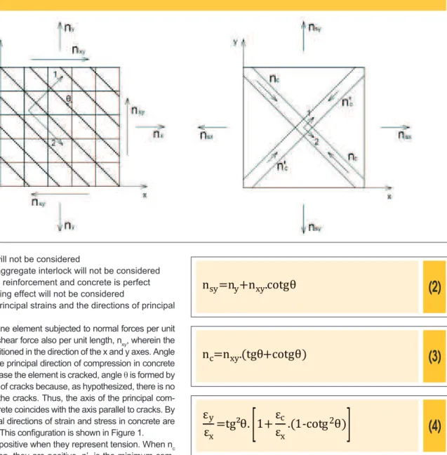
Considering a membrane element subjected to normal forces per unit length, nx and ny, and shear force also per unit length, nxy, wherein the reinforcements are positioned in the direction of the x and y axes. Angle
θ is formed between the principal direction of compression in concrete and the y direction. In case the element is cracked, angle θ is formed by axis y and the direction of cracks because, as hypothesized, there is no shear stress between the cracks. Thus, the axis of the principal com-pressive stress in concrete coincides with the axis parallel to cracks. By hypothesis, the principal directions of strain and stress in concrete are considered coincident. This coniguration is shown in Figure 1. Forces nsx and nsy are positive when they represent tension. When nc and n’c are compression, they are positive. n’c is the minimum com-pression in the element, when existing, and nc is the maximum com-pression. Figure 1 also shows this convention.
The problem consists in knowing forces nx, ny and nxy, inding the nec -essary area of reinforcement asx and asy and verifying if compressive
stress in concrete is below its strength. For this purpose, the equilib -rium and compatibility equations will initially be written for the situation in which the reinforcement is subjected to tensile stresses in the x and y directions. This result in expressions 1, 2, 3 and 4, where nsx
and nsy are the forces in the reinforcement in the x and y directions, respectively, and εy and εx are the strains in x and y and εc is the strain in concrete in the direction of principal compressive strain.
(1)
n
sx=n
x+n
xy.tg
θ
Thus, eliminating the reinforcement in the x direction, angle θ will no longer be 45 ° as mentioned, but will be determined by equa -tion 12.
(12)
θ
=arctg
(
--
n
n
x xy)
Thus, in the x direction, there is no reinforcement. Expression 13 determines the reinforcement in y direction.
(13)
a
sy=
n
f
sy yd=
n
y-
n
n
xyx²
f
ydTo verify the concrete stress, fcd2 will be used for the same reason
given for case I, as shown by Equation 14:
(14)
-n
x-
n
n
xyx²
h
≤f
cd2=0,6
(
1-f
ck250
)
.f
cd3.1.3 Case III – Reinforcement only in the x direction
Case III is similar to case II; the only difference is the reinforcement direction. Hence, for reinforcement to be necessary only in the x direction, the following inequations must be satisied.
(15)
n
sx=n
x+|n
xy|>0
(16)
n
sy=n
y+|n
xy|≤0
Similarly, also in this case, angle θ will not be 45 °, but is deter -mined by equation 17.
(17)
θ
=arctg
(
--
n
xyn
y)
In this case, asx is null and asy is given by equation 18.
(18)
a
sx=
n
f
sxyd
=
nx-
nxy
n
²
yf
ydThe veriication of concrete stress is given by expression 19. When the membrane is completely compressed, case IV is charac
-terized. In this case, reinforcement is not necessary.
This design method does not consider using of compression rein-forcement in any case.
3.1.1 Case I – Reinforcement in both directions
For reinforcement to be necessary in both directions, the following conditions must be satisied.
(5)
n
sx=n
x+|n
xy|>0
(6)
n
sy=n
y+|n
xy|>0
Thus, the reinforcement area is deined by 7 and 8, where fyd is the yield design stress of steel.
(7)
a
sx=
n
f
sxyd
=
n
x+|n
xy|
f
yd(8)
a
sy=
n
f
syyd
=
n
y+|n
xy|
f
ydFor verifying concrete in case I, fcd2 will be used, as suggested by
CEB [3] for the compressive strength because, in this case, con -crete is cracked. Thus, the expression is as follows.
(9)
2|n
xy|
h =f
cd2=0,6
(
1-f
ck250
)
.f
cd3.1.2 Case II – Reinforcement only in the y direction
In order to use reinforcement only in the y direction, nsx must be
nega-tive while nsy must be positive, satisfying the following expressions.
(10)
n
sx=n
x+|n
xy|≤0
(11)
(19)
-n
y-
n
n
xyy²
h
≤f
cd2=0,6
(
1--f
ck250
)
.f
cd3.1.4 Case IV – Membrane without reinforcement
In order not to use reinforcement, there can be no tensile stresses in membrane, thus loading conditions shall satisfy the following inequations.
(20)
n
sx=n
x+|n
xy|≤0
(21)
n
sy=n
y+|n
xy|≤0
Therefore, in this case, it must only check if the compressive stress in the concrete is less than the limit strength. For this veriication, differently from the other cases, it is used as a reference value fcd1
of CEB [3] for the strength of concrete, because there is no crack -ing in this case. From membrane equilibrium, this veriication can be written as:
(22)
(
- -
-
nx+ny
2 +
(
nx-ny
4 +n
)
²
xy²
)
.
-
1
h
≤
f
cd1=0,85.
(
1-
-
250
f
ck)
.f
cd3.2 Considerations about the study
of compression reinforcement
Keeping the design cases proposed by CEB [3] in mind, it will be examined which of them is consistent for studying compression reinforcement.
Firstly, in case I, compression reinforcement could only be effec -tively used if it were arranged in the direction of the cracks, which would help reduce compressive stress in the concrete. However, in this case, there is already an orthogonal grid of reinforcement, and if another layer of bars is placed in the other direction, the solution would be constructively bad, only recommended in special cases. Another possibility would be to use a larger reinforcement area than necessary to limit compression strain and to reduce stress in the princi -pal compressive direction. However, this solution would lead to a brittle rupture, because concrete would collapse before reinforcements yield. For cases II and III, it is reasonable to think that placing reinforce-ment in the direction that it was not reinforced, it will affect the stress ield in the membrane and it will reduce the compressive stress in the concrete.
For case IV, for which there is no reinforcement, it is evident that if reinforcement is placed appropriately in this membrane, it will help
to reduce the compressive stresses.
Therefore, this paper will only study design cases II, III and IV.
4. Strength model and veriication
of compressive stress in concrete
In the method based on Baumann`s criteria presented, the strength values of concrete follow those recommended by the CEB [3]. How -ever, this imposes a discontinuity of concrete strength between the case in which the concrete is cracked and that in which it is intact. Therefore, this work will be adopted a resistance model for the concrete that optimizes the use of the material. To do so, the ob -jective is to ind strength values for the concrete that are between fcd1 and fcd2, using the tensile strain that occurs perpendicular to the compressive strain as a parameter.
Vecchio and Collins [2] propose a formulation which includes concrete softening due to cracking differently from CEB [3]. For them, the loss of strength of cracked concrete is related to principal tensile strain ε1
im-posed on the membrane. Equations 23 and 24 deine the stress-strain diagram for the compression in the concrete proposed by Vecchio and Collins [2]. Considering the strain value that leads to stress peak in con-crete ε’c=2‰, equation 24 is obtained. Figure 2 shows this model.
(23)
f
c2=f
c2max.
[
2.
( (
ε
ε
`
2 c) )
-- --
ε
ε
`
2 c2
]
(24)
f
c2max=
0,8+170.
f`
cε
1
≤f`
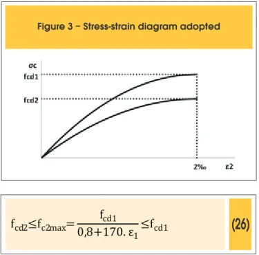
cExpression 23 is similar to that suggested by CEB [3] for the stress-strain diagram of concrete, only changing the strength limit. In this paper, it will use the limits proposed by CEB [3], but interpolated by equation 24. Thus, it follows that:
(25)
σ
c=f
c2max.
[
2.(
ε
ε
`
2 c)
-- --
(
ε
ε
`
2c
)
2]
(26)
f
cd2≤f
c2max=
0,8+170.
f
cd1ε
1
≤f
cd1The maximum strain used in this work is the same as that suggested by CEB [3] for zones subjected to axial compression, and this limit is 2 ‰. Thus, Figure 3 shows the stress-strain diagram used in this work.
4.1 Veriication of compressive strength of concrete
The strength limit for concrete is herein calculated considering the con-cepts presented in item 4. Thus, the way to check if the compressive force respects this limit is different from that presented in the method based on Baumann`s criteria, because the concrete capacity now de -pends on the tensile strain to which the membrane is subjected in ULS. In case IV, veriication of concrete is the same of that in item 3, because in this case there is no tension in the membrane and the compressive strength of concrete is always given by fcd1.
For the cases II and III, it should be irst checked if:
(27)
σ
c=
n
h ≥f
c cd1This study admits that fcd1 is the maximum limit for the compressive
strength of concrete in any case. If inequation 27 is satisied, the compressive stress in the concrete is above the limit and, it should thus evaluate the possibility of using compression reinforcement. The way to do this evaluation will be presented in item 5.
For the case in which inequation 27 is not satisied, it should be veriied if:
(28)
σ
c=
n
h ≤f
c cd2As fcd2 is the lowest limit for the compressive strength of concrete, if expression 28 is satisied, the compressive stress in the concrete
respects the strength limit imposed and it will not therefore be nec-essary to use compression reinforcement. If inequations 27 and 28 are not satisied, it consequently follows that:
(29)
fcd2≤
n
h ≤f
c cd1In this case, the strains in the membrane must be considered to de-termine the strength limits to be used, because it will depend on ε1. 4.1.1 Calculation to determinate the limit of compressive strength of the concrete
The objective of this item is to ind the value of fcd2max. However, it
depends on the strain of the membrane. A calculation method based on that presented by Jazra [12] will be presented. This calculation is valid for cases II and III. Due to their being analog, changing just the reinforcement position (y axis to case II and x axis to case III), only case III will be described. For case II, equation 30 must be replaced by the equivalent equation to εy and the same process must be re-peated. Thus, from Mohr circle, it follows that:
(30)
εx
=
ε1
+
2 +
ε2
(
ε1
2
-
ε2
)
.cos2
θ
So:
(31)
ε
1=
2.ε
x(1+cos2θ)
-ε
2.(1-cos2θ)
Therefore:
(32)
f
c2max=
f
cd10,8+170.
[
2.
ε
x-
ε
2.(1-cos2
θ
)
(1+cos2
θ
)
]
From equation 25 it is possible to express the compressive strain as a function of strength.
(33)
ε
2=
ε
`
c. 1- 1--
f
f
c2max
)
)
Considering by hypothesis that εx is equal to the yield strain of
steel, it follows that:
(34)
ε
2=
ε
`
c.
(
1- 1-
f
σ
cd1c(
For case II, equation 34 modiies and results in expression 35:
(35)
ε
2=
ε
`
c.
(
1- 1-
f
σ
cd1c(
0,8+170.
[
2.
ε
yd(1-cos2
-
ε
2.(1+cos2
θ
)
θ
)
]
Equations 34 and 35 can be solved by iterative methods. Assum -ing an initial value to ε2 for which the function exists (i.e., the radi-cand will not be negative), it will converge to the solution. If the radicand assumes a negative value in any iteration, then the prob -lem has no solution, and therefore the stress in concrete is higher than the maximum limit.
5. Design of compression reinforcement
for cases II and III
All the demonstrations in this item will be made only for design case III. Case II is analogous and only its inal formulation will be presented. For those cases in which the compressive stress in concrete is higher than the strength calculated as shown in item 4, it should be checked if adopting compressed reinforcement in the direction in which there was no reinforcement previously, it will be effective to decreases the stress in concrete so that it will be lower or equal to the strength. First, for the purposes of this problem the same assumptions given by the method based on Baumann`s criteria, presented in item 3, will be used.
Moreover, some considerations about strain must be made. First, it will be admitted that the strain in the x direction is equal to the yield stress in steel. This assumption limits the strain in the mem -brane, optimizing the compressive strength of the concrete, be -sides resulting in a reinforcement area in which ductile rupture in ULS occurs. In other words, even if to solve the problem it would be necessary to over-reinforce the membrane, this result will be discarded because the membrane would collapse in a brittle way. Furthermore, it is assumed that strain ε2 is always equal to ε’c, lead-ing the concrete to the strength limit and, consequently, reduclead-ing the consumption of reinforcement. Summarizing the hypotheses, it follows that:
1. The cracks are approximately parallel and straight. 2. The tensile strength of concrete is null
3. The dowel effect will not be considered
4. The effect due to aggregate interlock will not be considered 5. The bond between reinforcement and concrete is perfect 6. The tension-stiffening effect will not be considered
7. The directions of principal strains and the directions of principal stresses coincide
8. The strain in x direction is equal to the yield strain of steel (εx = εyd).
9. The principal compressive strain is equal to the strain resulting in the peak stress in concrete (ε2 = ε’c).
5.1 Design limits
With these hypotheses, it is intended to determine the cases in which it is possible to design compression reinforcement. Thus, irstly, a membrane subjected to stresses such that tensile rein
-forcement in the y direction is not necessary, therefore, it lies in de -sign case III, and the compressive stress in the concrete is higher than the strength fc2max, as shown in item 4 is assumed. As hypo -thetically εx = εyd and ε2 = ε’c, the compressive strength of concrete
is given by equation 36.
(36)
f
c2max=
f
cd10,8+170.
[
2.
ε
yd(1+cos2
-
ε
'
c.(1-cos2
θ
)
θ
)
]
In which:
f
cd2≤f
c2max≤f
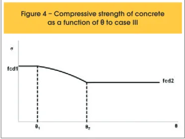
cd1The graph that describes the strength as a function of θ is shown in Figure 4. For case III, all the functions of θ have domain 0 ≤ θ ≤ |45º|. For case II, the domain is |45º| ≤ θ ≤ |90º|.
It can determine the values of θ1 and θ2 shown in Figure 4. Angle θ1 is the one which equates fc2max at fcd1. Thus, it can be demonstrated that:
(37)
θ
1=
arccos
(
0,00118-2.
(
ε
'ε
yd+
ε
'cc
-0,00118)
)
2
As the cosine function produces the same result, no matter the angle signal, both positive and negative θ1 are solutions. Similarly,
θ2 is the value that equates fc2max at fcd2. Thus, it follows that:
(38)
(
)
θ
2=
arccos
0,003627-2.ε
(ε
' yd+ε
'cc
-0,003627)
2
Also for θ2, both positive and negative solutions satisfy equation 38.
However, if θ exceeds a certain limit, strain εy assumes positive values. Thus, the area of reinforcement in y results in negative values, which is not physically possible. As by hypothesis εx = εyd
and ε2 = ε’c, it can calculate to what values of θ, εy is lower than
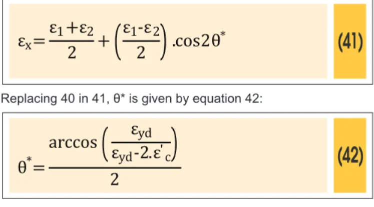
0. The objective is to ind θ* for which εy = 0. From Mohr circle, it follows that:
(39)
ε
1+ε
2=ε
x+ε
yThen:
(40)
ε
1=
ε
yd-
ε
'
cAlso through the Mohr circle, by replacing θ with θ*, it follows that:
(41)
ε
x=
ε
1+
2 +
ε
2(
ε
12
-
ε
2)
.cos2
θ
*Replacing 40 in 41, θ* is given by equation 42:
(42)
θ
*=
arccos
(
ε
ε
ydyd
-2.ε
'c)
2
Table 1 shows the values of θ1, θ2 and θ* to steels determined by NBR 6118 [14]. It can be observed that for steels CA-50 and CA-60 there are no values of θ1. This is because for strain values assumed by hypothesis for this problem, the strength of the concrete never reaches the value of fcd1 for these steels. Thus, the strength of con-crete reaches its maximum when θ = 0º. Thus, it equalizing strength with stress in concrete, if θ1 exists and θ = 0, then nxy = 0 and:
(43)
f
cd1=
n
h
cIf θ1 exists and 0 < θ ≤ |θ1|, then:
(44)
f
cd1=
h.sen(2
2.n
xyθ
)
Table 1 – Values of θ1, θ2 and θ* for steels
prescribed by NBR 6118 to case III
yd(‰)
o
|
θ
1| ( )
o
|
θ
2| ( )
o
|
θ
*| (
)
CA-25
1,04
12,17
42,74
39,07
CA-50
2,07
DOES NOT EXIST
31,74
35,03
CA-60
2,48
DOES NOT EXIST
26,79
33,74
If θ1 does not exist and θ = 0, so nxy = 0 and:
(45)
f
cd10,8+170.
[
2.
ε
yd(1+cos2
-
ε
'
c.(1-cos2
θ
)
θ
)
]
=
n
ch
If θ1 exists and |θ1|< θ < |θ2| or if θ1 does not exist and 0 < θ < |θ2|,
then:
(46)
f
cd10,8+170.
[
2.
ε
yd(1+cos2
-
ε
'
c.(1-cos2
θ
)
θ
)
]
=
2.n
xyh.sen(2
θ
)
If |θ2| ≤ θ < |θ*|, then:
(47)
f
cd2=
h.sen(2
2.n
xyθ
)
Considering this situation, the objective is to ind for which values of forces it is possible to design compression reinforcement. For normal forces, there is no mathematical limit, there is only con -structive limit to the reinforcement ratio prescribed by NBR 6118 [14]. For shear force, there is a limit, but the formulation of which varies with the kind of steel adopted. This is because limits θ1, θ2 and θ* are different for each steel. For CA-25, as |θ*| <|θ2|, equation 47 will never be valid. Thus, it should be known which maximum value of nxy can be assumed for this steel. Then, taking back equa -tion 46, it is possible to demonstrate that:
(48)
|n
xy|≤
f
cd1.h
2
.
(
(
sen(2.|
θ
xy|)
0,8+170.
[
2.
ε
yd(1+cos? (2.|
-
ε
'c.(1-cos(2.|
θ
θ
xy|))
xy
|))
]
In which:
(49)
|
θ
xy|=33,76°
For CA-50 and CA-60, as |θ*| > |θ2|, equation 47 is valid. From it, it
is possible to demonstrate that:
(50)
|n
xy|≤
f
cd2.h.sen(2|
2
θ
*|)
5.2 Design reinforcement in case III
Assuming a membrane that is subjected to forces which respects the con-ditions imposed by equations 48 and 50, the intention is to calculate the amount of reinforcement necessary to be positioned in the y direction in order to compressive stress in concrete is equal to the maximum strength fc2max. This calculation method was based that presented by Jazra [12]. Therefore, with equations 43, 44, 45, 46 and 47 the intention is to ind the value of θ which is the solution to the problem. First, if nxy = 0, then θ = 0°. If θ1 exists and 0 < θ ≤ |θ1|, so:
(51)
θ=
arcsen
(
2.nxy
fcd1.h
)
2
If θ1 exists and |θ1| < θ < |θ2| or if θ1 does not exist and 0º < θ < |θ2|, then:
(52)
θ=
arcsen
(
2.n
xyfcd1.h
0,8+170.
[
2.εyd-ε'c
(1+cos2θ)
.(1-cos2θ)
[
)
2
Finaly, if |θ2| ≤ θ < |θ*|, then:
(53)
θ=
arcsen
(
2.n
xyf
cd2.h
)
2
Therefore, to ind θ, it should follow the steps. 1. If nxy = 0, θ = 0.
2. If nxy ≠ 0, use the iterative method to ind θ through equation 52. 3. If converges, for CA-25, two solutions can be found, but it is
only valid that one which it respects θ <θmax.
4. If converges, for CA-25, check if θ ≤ θ1. Because equation 52 is not valid for this domain, θ must be found using equation 51. 5. If converges, for CA-50 and CA-60, θ found is solution. 6. If does not converge, ind the solution using equation 53. With values of εx = εyd, ε2 = ε’c and θ, it is possible to obtain the value of ε1 and εy. Taking back equation 31 and 39, then:
(54)
ε
y=
2.
ε
yd(1+cos2
-
ε
'
c.(1-cos2
θ
)
θ
)
+
ε
'
c-
ε
ydTable 2 – Maximums values for
θ
maxin case III
yd(‰)
o
θ
max( )
CA-25
1,04
CA-50
2,07
CA-60
2,48
33,76
35,03
33,74
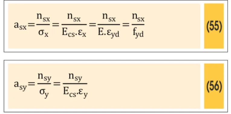
It is possible to calculate the forces in the reinforcement using equations 1 and 2. The reinforcements are given by:
(55)
asx
=
n
σ
sxx
=
n
sxEcs.
ε
x=
n
sxE.
ε
yd=
n
sxfyd
(56)
a
sy=
n
σ
syy
=
n
syE
cs.
ε
y5.3 Design reinforcement in case II
In this item, the formulation for designing compression reinforcement in case II will be presented. As already exposed, the demonstration of equa -tions is the same for case III and only the inal equa-tions will be presented here. Thus, for case II, the design limits presented in item 5.1 also must be considered, but the domain of functions of θ is |45°| ≤ θ ≤ |90°|. In this case, εy = εyd. By adapting expression 36, fc2max is
repre-sented by equation 57.
(57)
f
c2max=
f
cd10,8+170.
[
2.
ε
yd-
(1-cos2
ε
'c.(1+cos2
θ
)
θ
)
]
Thus, for case II, the limits of θ assume the values shown in Table 3. For CA-25, it follows that:
(58)
.
(
sen(2.|
θ
max|)
(
0,8+170.
[
2.
ε
yd-(1-cos(2.|
ε
'c.(1+cos(2.|θ
θ
max|))[
max|))
|n
xy|≤
f
cd12
.h
For CA-50 e CA-60, it follows that:
(59)
|n
xy|≤
f
cd2.h.sen(2|
2
θ
max|)
If the shear force to which the membrane is subjected respects condition 58 or 59, then the value of θ must be found by using the
Table 3 – Values of
θ
1,
θ
2e
θ
* and
θ
maxfor steels prescribed by NBR 6118 in case II
yd(‰)
o
|
θ
1| ( )
o
|
θ
2| ( )
o
|
θ
*| (
)
θ
(
o)
maxCA-25
CA-50
CA-60
same steps used in case III, but using the formulation found here-in. First, if nxy = 0, then θ = 90 °. If θ1 exists and |θ1| ≤ θ <90 °, then:
(60)
θ=
arcsen
(
2.nxy
fcd1
.h
)
2
If θ1 exists and |θ2| < θ < |θ1| or if θ1 does not exist and |θ2| < θ < 90º, then:
(61)
θ
=
arcsen
(
(
2.n
xyf
cd1.h
0,8+170.
[
2.
ε
yd-
(1-cos2
ε
'c.(1+cos2
θ
)
θ
)
[
2
Finally, if |θ*| < θ ≤ |θ2|, then:
(62)
θ=
arcsen
(
2.n
xyf
cd2.h
)
2
For case II, εyd = εy. So, with ε2 = ε’c e θ, it is possible to ind the
value of ε1 and then εx. Thus, it follows that:
(63)
ε
x=2.
ε
yd-
(1-cos2
ε
'c.(1+cos2
θ
)
θ
)
+
ε
'c
-
ε
ydIt is possible to calculate the forces in the reinforcement using equations 64 and 65. The reinforcements are given by:
(64)
a
sx=
n
σ
sx x=
n
sxE.
ε
x(65)
a
sy=
n
σ
syy
=
n
syE.
ε
y=
n
syE.
ε
yd=
n
syf
yd6. Design of compression reinforcement
to case IV
Case IV is different from cases II and III because the concrete strength conditioning is not the same. As in this case the membrane is in biaxial compression state, the concrete strength could be even higher than the value of fcd1, as recommended by the CEB [3]. How -ever, in this study, concrete strength will be considered equal to fcd1.
The objective of the formulation that will be presented is to design the reinforcement in x and y directions for membranes in which stress in concrete is higher than its strength.
First, it is assumed that stress in concrete is equal to its limit in ULS. Another problem hypothesis is that the membrane is always in biaxial compression state; in other words, the inclusion of rein-forcement which leads to tensile stress in membrane will not be contemplated by this study. Thus, the hypotheses are:
1. The tensile strength of concrete is null
2. The bond between reinforcement and concrete is perfect 3. The membrane is always in biaxial compression state
4. The directions of principal strains and the directions of principal stresses coincide
5. The concrete strength is given by fcd1
6. The principal compressive strain is equal to the strain resulting in the peak stress in concrete (ε2 = ε’c). Thus, the principal
com-pressive stress is equal to the comcom-pressive strength (σc = fcd1).
7. The effect due to aggregate interlock will not be considered 8. The tension-stiffening effect will not be considered
By equilibrium of membrane, the following expressions are obtained where n’c is the force in the direction of minimum compression.
(66)
n
c=-n
x+n
xy.cotg
θ
+n
sx(67)
n
c=n
sy-n
y+n
xy.tg
θ
(68)
n
c=n
c'+n
xy.(tg
θ
+cotg
θ
)
(69)
nc=-
(n
x-n
sx)+(n
2
y-n
sy)
+
((n
x-n
sx)-(n
4
y-n
sy))
2+nxy²
(70)
nc
'=-
(n
x-n
sx)+(n
2
y-n
sy)
-
((n
x-n
sx)-(n
4
y-n
sy))
2+nxy²
6.1 Design limits
The objective in this item is to deine the cases for which it is possi -ble to design compression reinforcement. By hypothesis, the mem -brane is always in biaxial compression state, then n’c ≥ 0. Thus,
from equation 68, it follows that:
(71)
sen2
θ
≥
2.nxy
n
Then:
(72)
|n
xy|≤
f
cd12
.h
Equation 72 means an absolute limit to nxy
As the assumptions deine only one ixed strain, there are ininite solutions within a range. The parameter that deines this interval is θ. Thus, it is interesting to delimit the angles θ which are possible to be assigned to the problem. Thus, using equation 71, it can be demonstrated that:
(73)
θ
c1≤
θ
≤
θ
c2In which:
(74)
θ
c1=arcsen
(
2.nxy
fcd1.h
)
2
o o
to 0 ≤
θ
≤ |45 |
(75)
o o
to |45 | ≤
θ
≤ |90 |
θ
c2=
arcsen
(
f
2.nxy
cd1.h
)
2
Besides this criterion, by hypothesis the membrane is always in biaxial compression state, the strains in any direction are always negative. Thus, in order to not obtain reinforcement area with a negative sign, which is an incongruity, the reinforcement forces should also be negative. Hence, in order to nsx ≤ 0, θ must respect the following premise.
(76)
θ
≤
θ
x=arctg
(
n
n
xyx
+n
c)
Similarly, in order to nsx ≤ 0, the following criteria must be followed.
(77)
θ
≥
θ
y=arctg (
n
c+n
yn
xy)
6.2 Reinforcement design
The method that will be presented was based on Jazra [12]. First, the forces to which the membrane is submitted must re-spect the equation 72. Once this criterion is veriied, it must arbitrate a value of θ such that it respects the limits imposed by inequations 73, 76 and 77. There will be ininite values pos
-sible to θ, but just one will lead to a minimal reinforcement area. Thus, it follows that:
(78)
n
sx=n
c+n
x-n
xy.cotg
θ
(79)
n
sy=n
c+n
y-n
xy.tg
θ
With nsx and nsy, it is possible to calculate n’c through expression 70. As the direction of the principal stress is the same of the direction of the principal strain by hypothesis, force n’c is related to strain ε1.
These terms are related by the constitutive model for the concrete. Therefore:
(80)
ε
1=
ε
`
c.
(
1- 1-
f
n
c'cd1
.h
)
Obtaining the value of ε1 and as the value of ε2 = ε’c and θ is known,
it is possible to calculate εx and εy through expressions 81 and 82,
obtained by the Mohr circle.
(81)
ε
x=
ε1
+
2 +
ε2
(
ε1
2
-
ε2
)
.cos2
θ
(82)
ε
y=
ε
1+
2 -
ε
2(
ε
12
-
ε
2)
.cos2
θ
Thus, reinforcement is designed by:
a
sx=
n
σ
sx x=
n
sxE
cs.
ε
xa
sy=
n
σ
syy
=
n
syE
cs.
ε
yThe reinforcement areas obtained are not necessarily the mini -mum. Therefore, attempts must be made to ind this mini-mum.
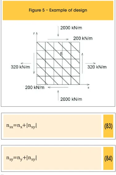
7. Example of design
(83)
n
sx=n
x+|n
xy|
(84)
n
sy=n
y+|n
xy|
Then:
n
sx=n
x+|n
xy|=320+|200|=500 kN/m
n
sy=n
y+|n
xy|=-2000+|200|=-1800 kN/m
From inequations 15 and 16, as nsx> 0 and nsy ≤ 0, it is not neces
-sary to use tensile reinforcement in y direction, which characterizes design case III. Then, irst, concrete stress must be veriied.
θ
=arctg
(
--
n
n
xy(
-y
)
=arctg - 200
-2000
)
=5,71°
n
c=n
xy.(tg
θ
+cotg
θ
)
n
c=200.(tg5,71°+cotg5,71°)=2020 kN/m
σ
c=
n
h =
c2020
0,12 =16833,33
kN
m
2=16,83 MPa
f
cd1=0,85.
(
1-
250
f
ck)
.f
cd=0,85. 1-
(
250 .
25
)
1,4=13,66 MPa
25
f
cd2=0,60.
(
1-
250
f
ck)
.f
cd=0,60. 1-
(
250 .
f
ck)
1,4=9,64 MPa
25
Figure 5 – Example of design
In this case σc > fcd1, the compressive stress in the concrete is
higher than the maximum limit of strength. Then, it will check if it is possible design compression reinforcement in the y direction to decrease the compressive stress in concrete.
First, because steel CA-50 is being used, it must verify if nxy
re-spects inequation 85.
(85)
|n
xy|≤
f
cd2.h.sen(2|
2
θ
*|)
Then, θ* will be calculated through equation 86.
(86)
θ
*=
arccos
(
ε
ydε
yd+2.2
)
2
θ
*=
arccos
(
(
2,07
2,07+2.2
)
)
2
=
arccos 2,07
6,07
2
=35,03°
Now, it is possible to ind the limit to nxy:
|n
xy|≤
9642,9.0,12.|sen(2.35,03)|
2
=543,7 kN/m
Therefore, because the nxy is lower than the limit, it is possible to calculate the compression reinforcement for this case. Thus, using equation 87, it follows that:
(87)
θ
=
arcsen
(
(
2.n
xyf
cd1.h
0,8+170.
[
2.
ε
yd+2‰.(1-cos2
(1+cos2
θ
)
θ
)
]
2
(
(
θ
=
arcsen
2.200
13660,7.0,12
0,8+170.
[
2.2,07‰+2‰.(1-cos2
(1+cos2
θ
)
θ
)
]
2
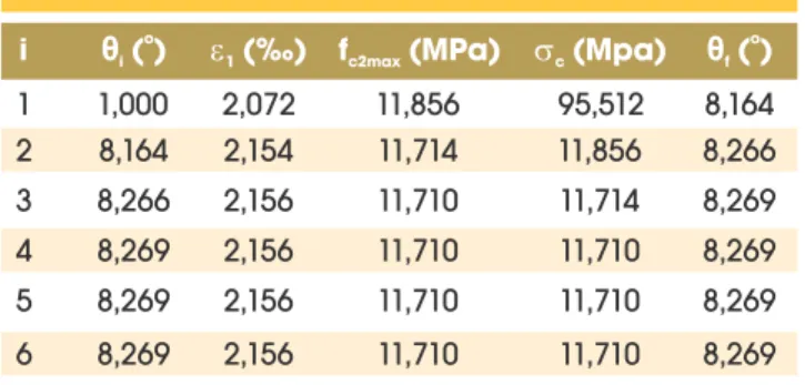
Iteratively, it is possible to obtain the value of θ. It can be seen from Table 4 that, in this case, value θ converges. In this example, the steel is assumed to be CA-50, it is not necessary to check if θ ≤ θ1,
because θ1 does not exist.
Going forward, it is now possible to calculate εy.
(88)
ε
y=
2.
ε
yd(1+cos2
-
ε
'
c.(1-cos2
θ
) +
θ
)
ε
'
c-
ε
ydThus, the forces in reinforcements are calculated
(89)
n
sx=n
x+n
xy.tg
θ
n
sx=320+200.tg8,27°=329,07 kN/m
(90)
n
sy=n
y+n
xy.cotg
θ
n
sy=-2000+200.cotg8,27°=-623,78 kN/m
Finally, the reinforcement areas are given by:
a
sx=
n
f
sx yd=
329,07
43,49 =7,57cm²
a
sy=
n
σy
sy=
E.
n
syεy
=
21000.(-1,91‰) =15,52 cm²
-623,78
8. Conclusions
Methods are presented herein to determine compression reinforcement in design case II, III and IV provided by CEB [3]. The limits for this design were also presented; in other words, cases in which it is possible to adopt compression reinforcement so that compressive stress in concrete is re-duced to its strength are delimited. In all the cases, these limits are only related to the shear force to which the membrane is subjected.
Furthermore, a model for concrete strength was used that interpo-lates the values of strength between fcd1 and fcd2 according to the curve obtained by Vecchio and Collins [2], so that there is no discon -tinuity of strength values between cases II and IV and cases III and IV. Also, we presented how to evaluate whether the compressive stress in the concrete is lower than the limit to this strength model. Due to this model adopted for concrete, for cases II and III, the re-inforcement design became more complex and iterative methods were necessary for resolution. However, it leads to fewer amounts of reinforcement than those found when using only the values sug-gested by CEB [3] for strength.
About case IV, it was found that there are ininite solutions for re -inforcement design, although just one leads to the minimum
rein-Table 4 – Iterative calculation of
θ
i
oθ
i( )
1(‰)
f
c2max(MPa)
c(Mpa)
o
θ
f( )
1
1,000
2,072
11,856
95,512
8,164
2
8,164
2,154
11,714
11,856
8,266
3
8,266
2,156
11,710
11,714
8,269
4
8,269
2,156
11,710
11,710
8,269
5
8,269
2,156
11,710
11,710
8,269
6
8,269
2,156
11,710
11,710
8,269
forcement required. This occurs due to the smaller number of ixed variables as compared to cases II and III. It is possible to ind the most economic solution design through the trial and error method.
9. References
[01] BAUMANN, T. Zur Frage der Netzbewehrung von Flachentragwerken. Der Bauingenieur, Vol. 47, Nº 10, 1972, p.367-377
[02] VECCHIO, F. J.;COLLINS M. P. The Modiied compression-Field theory for reinforced concrete elements subjected to shear. ACI Structural Journal. March- April, 1986, p.219-231
[03] COMITÉ EURO-INTERNATIONAL DU BETÓN. CEB-FIP model code 1990. London, Thomas Telford, 1993
[04] NIELSEN M. P., On the strenght of reinforced concrete discs, ACTA Polytechnica Scandinacia, Civil Engineering and Building Construction Series, Nº 10, Copenhagen, 1971
[05] GUPTA, AJAYA K. Membrane reinforcement in shells. Journal of the Structural Division,Proceedings of the American Society of Civil Engineers, v.107, January, 1981. p. 41-56.
[06] VECCHIO, F. J.;COLLINS M. P. Response of Reinforced Concrete to In-Plane Shear and Normal Stresses. Publication Nº 82-03, Department of Civil Engineering, University of Toronto, March, 1982, 332p.
[07] FIALKOW, M.N. Strength design of shell membrane reinforcement. Journal of Structural Engineering, v. 109, n. 4, 1983. p. 891-908.
[08] ACI COMITTEE 318. Building code requirements for structural concrete. American Concrete Institute, Detroit, 1977.
[09] GUPTA, AJAYA K; AKBAR H. Cracking in reinforced concrete analysis. Journal of Structural Engineering, v. 110, n. 8, 1984. p. 1735-1746.
[10] PETER, J. Zur Bewehrung von Scheiben und Schalen für Hauptspannungen Schiefwinkling zur
Bewehrungsrichtung, Dissertation, T. H. Stutgart, 1964. [11] CHEN, REINALDO. Dimensionamento de elementos
de superfície de concreto Armado: membranas, placas e cascas. 2004. 148 p. Dissertação (Mestrado) Escola Politécnica da Universidade de São Paulo, São Paulo, 2004.
[12] JAZRA, F. M. Dimensionamento de chapas de concreto armado. 2008. 126 p. Dissertação
(Mestrado) – Escola Politécnica da Universidade de São Paulo, São Paulo, 2008.
[13] LEONHARDT, F.; MONNIG, E. Construções de concreto v. 2: casos especiais de dimensionamento de estruturas de concreto armado, Rio de Janeiro, Interciências, 1978.
[14] ASSOCIAÇÃO BRASILEIRA DE NORMAS TÉCNICAS. Norma Brasileira NBR-6118: Projeto de estruturas de concreto. Rio de Janeiro, 2007.
concreto em estruturas laminares submetidas a solicitações de chapa e placa. In: Simpósio EPUSP sobre estruturas de concreto, 4, São Paulo, 2000. Anais. São Paulo, 2000.
[16] GUPTA, AJAYA K. Membrane reinforcement in shells: a review. Nuclear Engineering and Design, v.82, January,1984. p. 63-75.
[17] PEREIRA, F.A.C. Dimensionamento de estruturas de betão sujeitas a esforços de membrana associados com esforços de lexão de acordo com o Eurocódigo 2 – Faculdade de Engenharia da Universidade do Porto, Porto, 2010
[18] SILVA, T.F. Contribuição das armaduras de compressão em chapas de concreto armado. 2012. 115 p. Dissertação (Mestrado) – Escola Politécnica da Universidade de São Paulo, São Paulo, 2012.
10. Symbols
asx reinforcement area in x-direction asy reinforcement area in the y-direction ECS modulus of elasticity of concrete
fc’ characteristic compressive strength of concrete according to ACI
fc2 principal compressive concrete stress in concrete fcd design compressive strength of concrete fck characteristic compressive strength of concrete fcd1 design compressive strength of uncracked concrete fcd2 design compressive strength of cracked concrete fc2max maximum compressive strength of concrete fyd design yield stress of reinforcement fyk characteristic yield stress of reinforcement h thickness of membrane
nc maximum compressive force in concrete n’c minimum compressive force in concrete nx normal force in the x-direction
ny normal force in the y-direction nxy shear force in membrane
nsx reinforcement force in the x-direction nsy reinforcement force in the y-direction ε1 strain in direction 1
ε2 strain in direction 2
εx strain in direction x
εy strain in direction y
εsx reinforcement strain in the x-direction
εsy reinforcement strain in the y-direction εc maximum compressive strain in concrete
εc’ minimum compressive strain in concrete
εyd design yield strain of reinforcement
θ angle between y-axis and direction of principal compression in concrete
θ1 limit angle between curves fcd1 and fc2max
θ2 limit angle between curves fc2max e fcd2
θ* limit angle that deine εy sign
θmax limit angle to design of compression reinforcement in case II
and III
θxy angle that corresponds to maximum shear stress
θc1 limit angle to membrane remains in biaxial compressive
state in case IV
θc2 limit angle to membrane remains in biaxial compressive
state in case IV
θx limit angle to reinforcement force in y-direction to be of com
-pression in case IV
θy limit angle to reinforcement force in y-direction to be of com -pression in case IV
σc maximum compressive stress
σc’ minimum compressive stress