*e-mail: [email protected]
Computational Modeling of Ring Textures in Mesophase Carbon Fibers
Luiz Rogério Pinho de Andrade Limaa, Alejandro Daniel Reyb*
aDepartamento de Ciência e Tecnologia dos Materiais, UFBA,
R. Aristides Novis 2, 40210-630 Salvador - BA, Brazil
bDepartment of Chemical Engineering, McGill University,
3610 University Street, Montreal, Quebec, Canada H3A 2B2
Received: December 06, 2002; Revised: February 17, 2003
Carbon fibers are widely used in many industrial applications due the fact of their excellent properties. Carbonaceous mesophases are liquid crystalline precursor materials that can be spun into high performance carbon fibers using the melt spinning process, which is a flow cascade con-sisting of pressure driven flow-converging die flow-free surface extensional spinline flow that modifies the precursor molecular orientation structure. Carbon fiber property optimization requires a better understanding of the principles that control the structure development during the fiber formation processes and the rheological processing properties. This paper presents the elastic and continuum theory of liquid crystalsand computer simulations of structure formation for pressure-driven flow of carbonaceous liquid crystalline precursors used in the industrial carbon fiber spinning process. The simulations results capture the formation of characteristic fiber macro-textures and provide new knowledge on the role of viscous and elastic effects in the spinning process.
Keywords: carbon fibers, carbonaceous mesophases, liquid crystalline precursors, Ericksen-Leslie theory
mesophase pitch is an active area of research due to its sig-nificance in optimization and control of carbon fiber prop-erties. Since carbon fibers are the material of choice for high performance structural composites, significant indus-trial and academic research efforts are being conducted in many countries4,5.
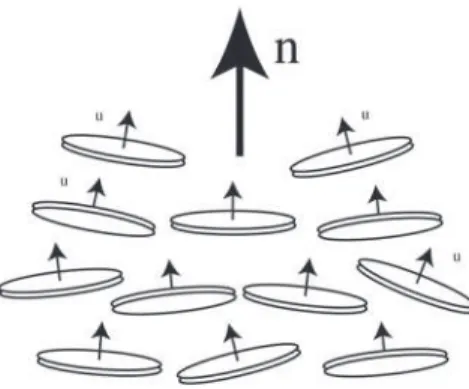
The manufacture of pitch carbon fibers uses carbo-naceous mesophases precursors in conjunction with the fiber melt spinning process. Carbonaceous mesophases are tex-tured anisotropic viscoelastic liquid crystalline materials formed by disc-like aromatic molecules. Therefore, this material is a discotic nematic thermotropic liquid crystal, that exhibits orientational order and positional disorder. Fig-ure 1 shows a schematic of the discotic nematic liquid crys-talline phase, where the unit normals to the molecular discs (u) orient more or less parallel to the director n (n.n=1).
The melt spinning process consists of a flow sequence that induces unique textural transformations in the mesophase. Figure 26 shows a schematic of the classical melt spinning process, consisting of a sequence of capillary Poiseuille flow, converging Jaffrey-Hamel flow, an extrusion Poiseuille flow, and finally the spinline extensional flow. Fiber melt spinning
1. Introduction
Carbon fibers are advanced materials widely used in aerospace, chemical, electronic, sportive, construction, and transportation industries due to their unique features such as low density, high thermal conductivity and shock resist-ance, low thermal expansion and high modulus. For instresist-ance, since the 1970s the civil and military aerospace industry has been progressively using a wide range of carbon-based materials in aircraft structures and disk brakes, rockets noz-zles and re-entry nose tips, and space shuttle components to improve structural efficiency and weight reduction with-out compromising the structural strength1-3.
of carbonaceous mesophase precursors usually lead to a va-riety of cross-sectional fiber textures, such as the folded, ra-dial, bipolar, and onion-skin textures, that give specific prop-erties to the fibers and its composites5,7.
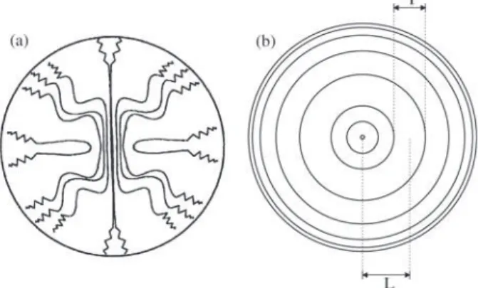
A typical folded texture and its molecular organization are shown in Fig. 38. If we neglect the oriented core, the texture consists basically of a set of rings located at L, whose thickness T decreases towards the fiber rim. The mecha-nisms that lead to concentric ring textures needs to be elu-cidated for the eventual optimization and control of pitch
based carbon fiber textures. This paper uses theory and simu-lation to formulate a flow-induced texture formation proc-ess, applicable to mesophase pitches subjected to capillary flow.
Theory and simulation for liquid crystalline flows is an active area of research9 given the importance of these mate-rials in structural, electromagnetic, sensor, lubrication, foams, and display applications. The most widely used mechanical theory is that of Ericksen-Leslie10-12, in which mass, linear momentum balance equations are coupled to angular momentum balance equation. The latter is basically a torque balance equation, in which viscous torques are balanced by elastic torques. Since the discotic mesophase display orientational order, the average orientation or di-rector is affected by external flow, a mechanism known as flow-induced orientation. In addition, these materials are elastic, such that spatial gradients of the director increase the energy. The three basic elastic storage modes, shown in Fig. 413 are: splay, twist, and bend, respectively. The tem-perature-dependent modules for each mode are K11, K22, and K33. Thus any imposed processing flow creates trough the balance between flow-induced orientation and elastic torques, a unique texture. The cross-sectional texture for mesophase fibers is just the spatial distribution of the direc-tor field: n = function (r,θ), where (r,θ) are the polar coor-dinates. In this paper we focus on how the average molecu-lar orientation n is affected by a steady capillary Poiseuille flow.
Figure 2. Processing sequence of mesophase carbon fibers. Adapted from McHugh6.
The specific objectives of this paper are: (1) to model the ring texture formation process for discotic mesophases subjected to steady pressure-driven capillary flow; (2) to characterize the processing conditions that lead to the emer-gence of ring patterns in the fiber cross-section, and (3) to characterize the pattern sensitivity for increasing pressure-drops.
This paper is organized as follows. First, we review the elastic and continuum theory of liquid crystalsfor uniaxial discotic nematic thermotropic liquid crystals, which is the case of the mesophase pitch, then we applied it to capillary Poiseuille flow, followed by discussions of flow-induced macro-textural phenomena.
2. Elastic and Continuum Theory of Liquid
Crystals
As mentioned previously, in flowing liquid crystal sys-tems the elastic and the viscous stresses are normally both
important. The static continuum theory of elasticity of liq-uid crystals developed by Oseen and Frank10,11, takes into account external forces that introduce deformations in the relative orientations and can distort the equilibrium con-figurations of liquid crystals. These deformations are called curvature strains, as opposed to the displacement strains present in isotropic materials. The anisotropic material re-sponds to such deformations with the appearance of restor-ing elastic torques. By assumrestor-ing an orientation Hooke’s law, a free energy density Fd is defined by the following expres-sion10-11:
(1)
where the director vector (n) and the elastic parameters (K) were defined in Figs. 1 and 4.
The dynamical continuum theory of uniaxial liquid crys-tals was developed by Ericksen and Leslie10-12. In this theory the microstructure of the material is explicitly taken into account. Assuming that the fluid is incompressible and that the director vector has the magnitude of a unit, the balance equations of micro-continuum mechanics are:
• Conservation of mass:
(2)
• Conservation of linear momentum:
(3)
• Conservation of energy:
(4)
• Director equation:
(5)
where,
(6)
(7)
(8)
D/Dt is the substantial derivative operator (D/Dt = ∂/∂t + v.∇), ρ is the mass density, v is the linear velocity, f is the body force per unit volume, σσσσσ is the total stress tensor, U is the internal energy per unit volume, A is Figure 4. Schematic representation of the three elastic modes in
discotic nematic liquid crystals. (a) splay (K11); (b) twist (K22); (c) bend (K33). Adapted from Sokalski and Ruijgrok13.
Figure 3. Schematic representation of the microstructure of fractured surfaces: a) shows the zig-zag pattern of folding becoming sharper and narrower toward the fiber edge (adapted from Pennock et al.8);
the rate of deformation tensor, W is the spin tensor, πππππ is the director stress tensor, N is the angular velocity of the direc-tor relative to that of the fluid, M is the gradient of
N ( ), G is the external director body force
(torque per unit volume), g is the intrinsic director body force, ρ1 is the moment of inertia per unit volume.
The Ericksen-Leslie constitutive equations for the stress tensor intrinsic director body force, and director stress ten-sor, developed by using the entropy production arguments are as follows10-12:
, (9)
, (10)
, (11)
where,
γ1 = α3 - α2 (12)
γ2 = α6 - α5 = α3 + α3 (13)
(14)
(15)
p is the pressure, I is the unit tensor, γ1 is the rotational viscosity that is positive, γ2 is the irrotational torque coeffi-cient, βββββ is a Lagrange multiplier vector, λ is the reactive parameter, θal,n is the flow-alignment angle that exist when
λ<-1, and {αi}, i=1…6, are the six Leslie viscosity coeffi-cients of a nematic liquid that are linked by one relation (Eq. 13), and by the follows inequalities10-12:
α4≥ 0 (16)
2α1 + 3α4 + 2α5 + 2α6 ≥ 0 (17)
2α4 + α5 + α6 ≥ 0 (18)
(α3 - α2)(2α4 + α5 + α6) ≥ (α2 - α3)2 (19)
In the case of DNLC the follows additional inequalities are also verified:
α3 > α2 (20)
α2 > 0 (21)
The Ericksen-Leslie theory predicts that for sufficiently large deformation rates, the director orients in the shear plane along the flow-alignment angle10-12. When the director field is homogeneous (∇n = 0) and oriented at the alignment angle, the viscous and elastic torques vanish. Eq. 15 shows that the alignment angle is not unique. The primary alignement angle (n = 0) defines the primary solution de-noted by Po, and secondary alignement angles (n > 1) de-fine secondary solutions denoted by Sn.
The Leslie viscosity coefficients are related with the Miesowicz’s viscosities10, which are measured in a steady simple shear flow between parallel plates with fixed tor orientations along three characteristic orthogonal direc-tions by applying a strong magnetic field. For orientation parallel to the flow: η1 = (α3 + α4 + α6)/2, parallel to the velocity gradient: η2 = (-α2 + α4 + α5)/2, and perpendicular to both the flow and velocity gradient: η3 = α4/2. For discotic nematic liquid crystals the relative ordering in magnitude of the Miesowicz’s viscosities is η1 > η3 > η2.
The stress asymmetry expresses the fact that moment of momentum is not conserved, but the sum of both external and internal angular momentum is10. The conservation equa-tions for internal and external angular momentum are cou-pled by the antisymmetric part of the stress tensor. This fact is a direct result of the non-radial mechanical interaction between adjacent fluid regions and should be accounted for in cases where the internal structure describes the kinematical state of a fluid.
3. Capillary Poiseuille Flow
Here we present some results of the Poiseuille capillary flow of discotic nematic liquid crystals computed using the Ericksen-Leslie equations (Eqs. 1-11) with the objective of capturing flow-induced macro-textural phenomena that lead to a concentric ring texture. The system is assumed isother-mal and at steady state. In addition, the director orientation vector is confined to the (r, z) plane and the velocity field v
is in the axial direction, as follows11:
n(r) = (sinθ(r), 0, cosθ(r)) (22)
v(r) = (0, 0, v(r)) (23)
More general field dependencies are possible but be-yond the scope of this paper. The resulting governing equa-tions in dimensionless form for the director tilt angle (θ) and axial velocity component ( ) are14:
(25) where , (26) (27) (28) (29) (30) (31)
ε is the ratio of the bend and the splay Frank elastic con-stants, Er is the ratio of viscous flow effects to long-range elasticity effects, and is known as the Ericksen number,
dz
dp is the given pressure drop in the capillary per unit length, is the dimensionless radial distance ( ), i are the dimensionless Leslie viscosities coefficients, is the average Miesowicz’ viscosity, R is the capillary radius,
and is the scaled velocity ( ).
The orientation equation (Eq. 24) was solved numeri-cally using the Galerkin Finite Element method, and its in-tegrals were computed using three points Gaussian quadrature. The resulting set of non-linear equations was solved using the Newton-Raphson iteration scheme, and mesh independence was established using standard mesh refinement criteria15. The velocity profiles in the capillary (Eq. 25) were calculated by using Gaussian quadrature in-tegration.
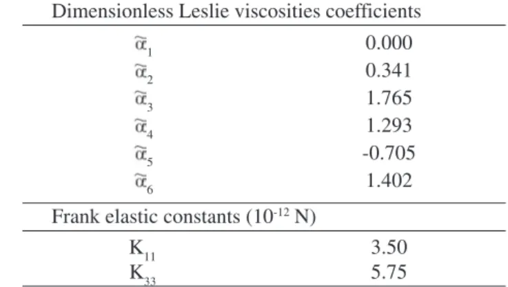
The simulations were carried out using the parameters showed in Table 1, which correspond to the Frank elastic constants measured to hexakis(dodecanoyloxy)truxene and the six scaled Leslie coefficients calculated from non-equi-librium molecular dynamics simulations16. The macro-tex-tural phenomena discussed in this paper are independent of the exact values of the viscoelastic parameters, but arises whenever λ<-1. The orientation in the center of the capil-lary and the anchoring angle at the wall was assumed to be zero. The former is due to symmetry and the latter due to usual strong anchoring at the walls10. For velocity we use the classical assumption of no slip at the wall.
4. Simulation of Flow-Induced
Macro-Textural Phenomena
The texture formation due to elastic effects fails17 to cap-ture the length scales gradients that are shown in real fibers. This paper presents the texture formation model, which is driven by flow effects, and retains the elastic effects. As shown below the length scale distribution in the predicted flow-in-duced texture, in contrast to the elastic-inflow-in-duced texture17, is consistent with experimental data, shown schematically in Fig. 3.
Figure 5a shows the director orientation (θ), obtained from Eq. 24, as a function of dimensionless radial distance for Er = 10000 for the primary (n = 0) and five selected sec-ondary (Sn, n=+4, +5, +9, +14, +16) solutions. The corre-sponding five dimensionless velocity profiles ( ), obtained from Eq. 25, of the secondary solutions are shown in Fig. 5b. It should be noted that the missing secondary solutions below the secondary solution S+16 are not included for the sake of clarity, but they exist and are stable14. Figure 5a shows that higher order solutions exhibit a narrow align-ment region in between core and rim regions over which the director vector exhibits also the same orientation peri-odically. On the other hand the low order solutions exhibit alignment over a wide annular region and narrow core and rim regions. A unique feature of liquid crystals is the cou-pling of velocity and orientation. Figure 5b is a typical ex-ample of how a periodic orientation field is reflected on the velocity profile. The velocity profile is locally and periodi-cally perturbed from the Newtonian parabolic profile due to the periodic orientation changes. The number of local-ized perturbation is equal to the order of the solution. For example, the S+9 profile has nine localized perturbations.
The solution multiplicity can help to explain macro-tex-tural phenomena, such a multiple concentric ring forma-tion, found in the flow processing of carbon mesophases. Table 1. Parameter values16.
Dimensionless Leslie viscosities coefficients
1 0.000 2 0.341 3 1.765 4 1.293 5 -0.705 6 1.402
Frank elastic constants (10-12 N)
K11 3.50
Figure 6 shows computed gray scale plots of the orienta-tion profile shown in Fig. 5a, for the n = 16(a), 14(b), 9(c), 5(d), and 4(e) secondary solutions. In the figures black cor-responds to θ = 1.157+kπ radians and white corresponds to
θ = 0 + kπ radians. The computed visualization of the
ori-Figure 5. a) Director angle θ as a function of dimensionless radial distance for the principal P0, and five second secondary (Sn; n = +4, +5, +9, +14, +16) solutions for θw= 0. b) Dimensionless
velocity as a function of dimensionless radial distance for five secondary solutions (Sn; n = +4, +5, +9, +14, +16).
entation profiles give a ring texture with a characteristic ring thickness that is a function of position. The figures show that the number of rings is equal to the order of the solu-tion. For example the n = 4 solution has four rings, and so on. All the textures have three regions: (1) a small core region surrounding the fiber axis, (2) a large ring (black band) in the central annular region, and (3) an outer rim region dense with thin rings. As n increases the width of the annular region decreases and the number of rings in the rim region increases.
Figure 7 shows the computed rings thickness (T) as a function of its radial position (L) as it is defined in Fig. 3b for n = 4, 5, 9, 14, 16 secondary solutions, and Er = 10000. The figure shows the presence of the three regions. As the order of the solution (n) increases, more thinner rings ap-pear close to the rim. Thus the model predictions are con-sistent with experiments. The rim region has a thin tural length scale, while the core region has a large struc-tural length scale. The origin of the texture length scale is set by the orientation gradient length scale. For higher or-der solutions, as the director rotates from θal to zero, the texture length scale T is set by the magnitude of the orienta-tion gradient:
(32)
where β is of order one.
rates close to the wall, it will refine the texture length scale T. The pressure drop has almost no effect at the core because at the center the shear rate vanishes and the struc-ture remains unaffected by the flow.
Figure 11 shows the thickness and location of the annu-lar region for the S+4 solution. The figure shows that as the pressure drop increases the location and thickness of the aligned annular region increases monotonically. Thus lower pressure drops produce more uniform textures than larger pressure drops. Since the number of rings remains constant, an increase in the annular region will result in compression of the rim region.
5. Conclusions
Further progress, optimization, and control of the in-dustrial spinning of high performance mesophase carbon fibers will be based on cost-effective accurate models based in liquid crystal science. In this paper we have presented Figure 7. Ring thickness (T)as a function of ring location (L) for the five secondary solutions (Sn; n = +4, +5, +9, +14, +16), Er = 10000 and ε = 1.64.
Figure 6. Scientific visualisation for the fibre cross section shown the average orientation, where the black color corresponds to alignment with the stable Leslie angle (θ = 1.157+kπ radians) and the white color correspond to the orientation in the flow direction (θ = 0+kπ radians). for Er = 10000 and ε = 1.64. a) Secondary solution S+16; b) Secondary solution S+14; c) Secondary solution S+9; d) Secondary solution S+5; e) Secondary solution S+4.
representative modeling results of an ongoing research pro-gram that aims at developing the fundamental rheological and processing flow principles needed to establish a sci-ence-based fiber manufacturing. We have shown modeling results that capture macro-textural phenomena, such as ring formation on carbon fiber textures of carbonaceous mesophases.
Acknowledgements
This research was supported by a grant from the Engi-neering Research Centers (ERC) Program of the National Science Foundation (NSF- USA) under Award Number EEC-9731680.
References
1. Ford, T. “Aerospace Composites”, Aircraft Engineering and Aerospace Technology, v.9, n. 4, p. 334-342, 1997. 2. Windhorst, T.; Blount, G. “Carbon-Carbon Composites:
a Summary of Recent Developments and Applications”,
Materials & Design, v. 18, n. 1, p. 11-15, 1997. 3. Chung, D.D.L. Carbon Fiber Composites,
Butterworth-Heinemann, Newton, MA, 1994.
4. Edie, D.D. “Carbon fiber processing and structure/prop-erty relations”, in Rand, B.; Appleyard, S.P.; Yardim, M.F. (Eds.), Design and Control of Structure of Advanced Carbon Materials for Enhanced Performance, Kluwer Academic Publishers, Netherlands, p.163-181, 2001. 5. Peebles Jr, L.H. Carbon Fibers-Formation, Structure, and
Properties, CRC, Boca Raton, FL, 1995.
6. McHugh, J.J. The Development of Orientation in
Mesophase Pitch During Fiber Formation (Carbon),PhD Thesis, Clemson University, USA, 1994.
7. Matsumoto, T. “Mesophase Pitch and its Carbon Fibers”,
Pure & Appl. Chem., v. 57, n. 11, p. 1553-1562, 1985. 8. Pennock, G.M.; Taylor, G.H.; Fitz Gerald, J.D. “Micro-Figure 11. Thickness and location of the aligned annular region as
a function of the Erickssen number to the secondary solution S+4.
Figure 10. Rings thickness (T)as a function of ring location (L) to the secondary solution S+4, ε = 1.64, and Er = 2728, 5000, 7500, and 10000. Semi-log plot to all rings.
structure in a series of mesophase pitch-based fibers from DuPont: zones, folds, and disclinations”, Carbon, v. 31, n. 4. p. 591-603, 1993.
9. Rey, A.D.; Denn, M.M. “Modeling Liquid Crystalline Flows”, Annual Reviews in Fluid Mechanics, v. 34, p. 233-266, 2002.
10. de Gennes P.G.; Prost, J. The Physics of Liquid Crys-tals, 2nd Edn, Oxford University Press, London, 1993. 11. Chandrasekhar, F.R.S. Liquid Crystals, 2nd Edn.,
Cam-bridge: University Press, 1992.
12. Leslie, M. “Theory of flow phenomena in liquid crys-tals”, Adv. Liq. Cryst., v. 4, p. 1-81, 1979.
13. Sokalski, K.; Ruijgrok, T.W. “Elastic constants for liquid crystals of disc-like molecules”, Physica A: Statistical and
Theoretical Physics, v. 113, n. 1-2, p. 126-132, 1982. 14. de Andrade Lima, L.R.P.; Rey, A.D. “Poiseuille Flow of
Leslie-Ericksen Discotic Liquid Crystals: Solution Mul-tiplicity, Multistability, and Non-Newtonian Rheology”,
Journal of Non-Newtonian Fluid Mechanics, v. 110, n. 2-3, p. 103-142, 2003.
15. Fletcher, C. A. J. Computational Galerkin Methods, Springer-Verlag, New York, 1984.
16. Ho, S.K.; Rey, A.D. “Orienting Properties of Discotic Nematic Liquid Crystals in Jeffrey-Hamel Flows”,
Rheological Acta, v. 30, p. 77-88, 1991.