DOI: http://dx.doi.org/10.1590/1516-1439.313114
Materials Research. 2015; 18(5): 904-907 © 2015
*e-mail: [email protected]
1. Introduction
Ti-6Al-4V alloy is one of the most studied and used titanium alloys in the aeronautics industry. Its (α + β) phase is responsible for the high-hardness and low-density characteristics1. However, titanium and its alloys present a high afinity to certain chemical elements such as oxygen, requiring a surface protection to minimize its harmful effects, especially at high temperatures2. The use of high-adhered protective coatings, such as silicon carbide (SiC), can create a barrier to the action of oxygen, increasing the lifetime of the alloys3,4. Amorphous SiC ilms can be deposited at low temperatures by techniques assisted by cold plasmas3,5.
Among the plasma assisted techniques for deposing ilms, DCMS (Direct Current Magnetron Sputtering) and RFMS (Radio Frequency Magnetron Sputtering) are most used. However, a very promising technique, High Power Impulse Magnetron Sputtering (HiPIMS), has recently been studied6-8. In a HiPIMS discharge, the electron density can achieve 1018 m-3, which is 2 to 4 orders of magnitude higher than for DCMS, reducing the mean ionization distance to a few centimeters. Therefore, the sputter probability of ionized species is higher in a HiPIMS discharge9. These species can be accelerated toward the substrate; as a consequence, the adhesion, hardness, and homogeneity of the ilms can be improved.
However, even using the HiPIMS technique, in some cases the energetic bombardment of the substrate by the sputtered particles is not high enough to obtain good ilm-substrate adhesion10. In these cases, an interlayer can
minimize the lattice mismatches, reducing the stresses at the coating-substrate interface.
This work investigated the inluence of the Cr interlayer on the adhesion of SiC ilms deposited on Ti-6Al-4V substrates. Both, Cr and SiC ilms were deposited by the HiPIMS technique.
2. Experimental
The surface of the specimen was manually polished and then ultrasonically cleaned with acetone prior to the depositions. SiC ilms were deposited on Ti-6Al-4V substrates using the HiPIMS technique. A Cr interlayer was deposited in order to improve the adhesion between the SiC ilm and the substrate. All the ilms were deposited at working pressure and argon low rate of 6.7x10⁻¹ Pa and 20 sccm, respectively. Table 1 shows the deposition parameters. The purity of the SiC and Cr targets were 99.5% and 99.95%, respectively.
The morphology of the ilms was analyzed by scanning electron microscopy (SEM) and atomic force microscopy (AFM). The thickness and stoichiometry of the ilms and interlayers were measured by LayerProbe - SEM-energy dispersive spectrometer (EDS)11.
LayerProbe is a non-destructive new software tool for thin ilm analysis in the SEM-EDS systems. This probe allows calculation of the composition and thickness of the individual layers (from 2 nm to 2000 nm) beneath the surface using the x-ray emitted from the sample.
The ilm/substrate adhesion was analyzed using an ultra-micro tribometer from CETR (Center for Tribology) on the scratching test mode. The tests were performed by
Use of Cr Interlayer to Promote the Adhesion of SiC Films Deposited on
Ti-6Al-4V by HiPIMS
Abrão Chiaranda Merija, Tarcila Sugaharaa, Gislene Valdete Martinsb, Argemiro Soares da Silva Sobrinhob,
Danieli Aparecida Pereira Reisa,b, Polyana Alves Radi Gonçalvesb,c, Marcos Massia,b*
aUniversidade Federal de São Paulo – UNIFESP, Rua Talim, 330, CEP 12231-280,
São José dos Campos, SP, Brazil
bDepartamento de Ciência e Tecnologia Aeroespacial – DCTA, Instituto Tecnológico de Aeronáutica – ITA,
Praça Mal. Eduardo Gomes, 50, CEP 12228-900, São José dos Campos, SP, Brazil
cInstituto de Pesquisa e Desenvolvimento - IP&D, Universidade do Vale do Paraíba - UNIVAP,
Av. Shishima Hifumi, 2911, CEP 12244-000, São José dos Campos, SP, Brazil
Received: July 31, 2014; Revised: July 3, 2015
In this paper, chrome (Cr) thin ilms were deposited and used as interlayer between SiC ilms and Ti-6Al-4V substrates. Films and interlayers were obtained by using HiPIMS (High Power Impulse Magnetron Sputtering) technique. Interlayers were growth for 5, 30, and 60 minutes. The ilms were analyzed with respect to morphology, stoichiometry, thickness, roughness, and adhesion. The results showed that the HiPIMS technique was eficient to produce dense thin ilms and that the adhesion increased with Cr thickness.
Use of Cr Interlayer to Promote the Adhesion of SiC Films Deposited on Ti-6Al-4V by HiPIMS
2015; 18(5) 905
using a Diamond Rockwell-C tip, according to ASTM C1624. A progressive normal load was applied from 0.2 N to 25 N, for 10 mm, at 0.1 mm.s-1 sliding speed. In this test, the irst critical load (LC1) was deined as the load (N) necessary to crack the ilm and the second (LC2) as the load necessary to remove the ilm and expose the substrate on track12,13.
3. Results e Discussion
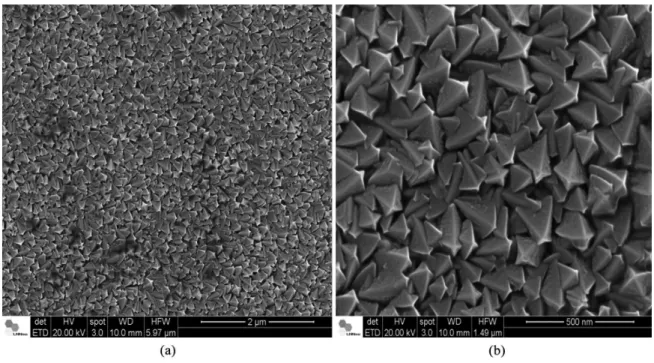
The chromium interlayer (Sample 1) obtained is a dense and homogeneous ilm with pyramidal shape morphology, as can be observed in SEM image (Figure 1).
Figure 2 shows the surface morphology of the Cr interlayer and the SiC ilms (samples 1- 4) obtained by AFM. The root mean square (RMS) roughness values are summarized in Table 2. The increase in the surface roughness by the Cr interlayer and the reduction of the lattice mismatch between the materials could be responsible for the SiC adhesion14.
The results obtained with the Layer Probe indicated that the SiC ilms deposited are stoichiometric. One of the spectra for sample 3 is shown in Figure 3. The SiC and Cr thicknesses of samples 2, 3, and 4 are shown in Table 3.
As expected, both Cr and SiC thicknesses increased with the deposition time.
The results indicated that LayerProbe is a very important technique to determine the thickness of individual layers of a multilayer material.
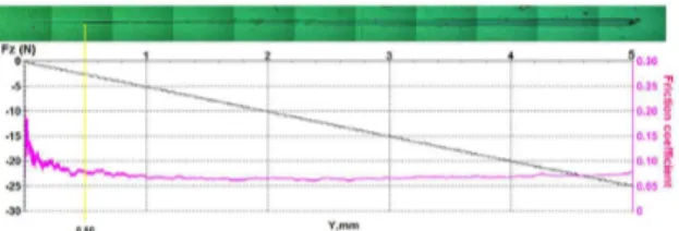
Figures 4, 5, and 6 show the friction coeficient and applied load obtained by the scratch test of samples 2, 3, and 4, respectively. The vertical yellow line indicates the position of LC1, and the vertical green line indicates the position of the LC2, which are related to the irst fracture and the total ilm delamination from the substrate, respectively. The black curves show the applied force and the pink curves show friction coeficient. These tests results are summarized in Table 4.
It is possible to observe in the scratch test results that sample 2 and 4 presented lower value for LC1 and for LC2. As the LC1 is related to cohesive failure and LC2 to adhesive failure, samples 2 and 4 presented lower cohesive adhesion and lower adhesion compared to sample 3. Samples 2 and 4 presented lateral cracks on the beginning of the track and wedging spallation followed by delamination after LC2,
Table 1. Deposition parameters.
Sample Target / substrate distance (mm)
Cr interlayer SiC ilm
Deposition time (min)
Average power (W) Deposition time (h) Average power (W)
1
155
30
200
--
--2 5
2 300
3 30
4 60
Merij et al.
906 Materials Research
while sample 3 presented just lateral cracks on all track, which shows good adhesion.
For samples 2 and 4, changes in friction coeficient were observed when the substrate is exposed. The SiC friction coeficient has an average value of 0.18 and arrives at 0.32 when the substrate is exposed.
Table 2. Roughness (rms) of the Cr interlayer and of samples 2, 3, and 4.
Sample Roughness (rms)-(nm)
1 (Cr interlayer) 15.6
2 15.8
3 18.4
4 24.7
Figure 2. AFM images of the (a) sample 1, (b) sample 2, (c) sample 3, and (d) sample 4.
Figure 3. EDS spectra obtained with LayerProbe (sample 3).
Table 3. Thickness of the ilms.
Sample Cr interlayer thickness
(nm)
SiC ilm thickness
(nm)
Total thickness (nm)
2 51 432 483
3 266 311 576
4 625 350 975
Use of Cr Interlayer to Promote the Adhesion of SiC Films Deposited on Ti-6Al-4V by HiPIMS
2015; 18(5) 907
References
1. Leyens C and Peters M. Titanium and titanium alloys: fundamentals and applications. Wiley-VCH; 2003. p. 333-350.
2. Razavi RSH, Salehi M, Monirvaghefi M and Gordani GR.
Corrosion behaviour of laser gas-nitrided Ti–6Al–4V alloy in nitric acid solution. Journal of Materials Processing Technology. 2007; 203(1-3):315-320. http://dx.doi.org/10.1016/j.
jmatprotec.2007.10.020.
3. Barricarte SMJ. Deposición de capas constituyentes de estruturas multicapa com funciones controlables eléctricamente. [Dissertation] España: Universidad de Zaragosa; 2006.
4. Da Silva LLG, Ueda M, Silva MM and Codaro EN. Corrosion
behavior of Ti–6Al–4V alloy treated by plasma immersion ion implantation process. Surface and Coatings Technology. 2007; 201(19-20):8136-8139. http://dx.doi.org/10.1016/j. surfcoat.2006.03.054.
5. Oliveira AR. Dopagem elétrica de filmes finos de carbeto de silício amorfo hidrogenado (a-SiC:H) obtido por PECVD. [Dissertation]. São Paulo: Escola Politécnica da Universidade de São Paulo; 2012.
6. Lundin D and Sarakinos K. An introduction to thin film processing using high-power impulse magnetron sputtering.
Journal of Materials Research. 2012; 27(5):780-792. http://
dx.doi.org/10.1557/jmr.2012.8.
7. Luo Q, Yang S and Cooke KE. Hybrid HiPIMS and DC
magnetron sputtering deposition of TiN coatings: Deposition rate, structure and tribological properties. Surface and Coatings Technology. 2013; 236:13-21. http://dx.doi.org/10.1016/j. surfcoat.2013.07.003.
8. Holtzer N, Antonin O, Minea T, Marnieros S and Bouchier D. Improving HiPIMS deposition rates by hybrid RF/HiPIMS
co-sputtering, and its relevance for NbSi films. Surface and Coatings Technology. 2014; 250:32-36. http://dx.doi.org/10.1016/j. surfcoat.2014.02.007.
9. Poolcharuansin P. The development of electrical plasma diagnostics for HiPIMS discharges. [Thesis]. England: University of Liverpool; 2012.
10. Wang YY, Kusumoto K and Lia CJ. XPS analysis of SiC films
prepared by radio frequency plasma sputtering. In: Proceedings of the 18th International Vacuum Conference (IVC-18); 2012;
Beijing, China.
11. Statham PJ. Feasibility of X-Ray analysis of multi-layer thin
films at a single beam voltage. IOP Conference Series: Materials Science and Engineering. 2010; 7:012027.
12. Burnett PJ and Rickerby DS. The relationship between hardness and scratch adhesion. Thin Solid Films. 1987; 154(1-2):403-416. http://dx.doi.org/10.1016/0040-6090(87)90382-8.
13. Burnett PJ and Rickerby DS. The scratch adhesion test: an elastic-plastic indentation analysis. Thin Solid Films. 1988; 137(2):233-254. http://dx.doi.org/10.1016/0040-6090(88)90006-5.
14. Ehiasarian AP, Wen JG and Petrov I. Interface microstructure
engineering by high power impulse magnetron sputtering for the enhancement of adhesion. Journal of Applied Physics. 2007; 101(5):054301. http://dx.doi.org/10.1063/1.2697052.
15. Capote G, Bonetti LF, Santos LV, Trava Airoldi VJ and Corat
EJ. Adherent amorphous hydrogenated carbon films on metals deposited by plasma enhanced chemical vapor deposition.
Thin Solid Films. 2008; 516(12):4011-4017. http://dx.doi.
org/10.1016/j.tsf.2007.08.007. Figure 5. Friction coeficient (pink) and applied load (black) as a
function of track distance obtained for scratching test for sample 3.
Figure 6. Friction coeficient (pink) and applied load (black) as a function of track distance obtained for scratching test for sample 4.
Table 4. Critical loads of the sample.
Sample LC1 (N) LC2 (N)
2 4.2 ± 3.0 18.5 ± 2.9
3 4.0 ± 1.7 >25.0
4 4.5 ± 0.5 10.5 ± 2.4
For samples 2 and 3, a higher interlayer thickness led to a higher adhesion to SiC ilm. For sample 4, the lowest LC2 was observed, which probably occurred because the interlayer thickness is too high (higher than SiC ilm), leading to a high stress on it15.
4. Conclusions
Cr thin ilms improved the adhesion between SiC ilm and Ti-6Al-4V substrate probably caused by the increase in the surface roughness. The increase of Cr layer thickness increased the adhesion of SiC ilms. The best adhesion of the SiC ilm was observed for sample 2 (30 min Cr and 2 h SiC).
SEM images indicated a dense and homogeneous distribution of pyramidal shape in the Cr ilm surface, produced by the HiPIMS technique.
LayerProbe was a very eficient technique to determine the thickness of individual layers of a multilayer material.