Rita Paula Paiva Craveiro
Mestre em Química
Engineering Bio-based Polymers using
Alternative Solvents and Processes
Dissertação para obtenção do Grau de Doutor em Química Sustentável
Orientador: Doutor Alexandre Babo de Almeida Paiva,
Universidade Nova de Lisboa
Co-orientador: Doutora Ana Rita Cruz Duarte,Investigadora
Auxiliar
ICVS/3B’s
Co-orientador: Professora Doutora Susana Filipe Barreiros,
Professora Associada, Universidade Nova de
Lisboa
iii
Universidade Nova de Lisboa
Rita Paula Paiva Craveiro
Mestre em Química
Engineering Bio-based Polymers using
Alternative Solvents and Processes
Dissertação para obtenção do Grau de Doutor em Química Sustentável
Orientador: Doutor Alexandre Babo de Almeida Paiva,
Universidade Nova de Lisboa
Co-orientador: Doutora Ana Rita Cruz Duarte,Investigadora
Auxiliar ICVS/3B’s
Co-orientador: Professora Doutora Susana Filipe Barreiros,
Professora Associada, Universidade Nova de
Lisboa
iv
Engineering Bio-based Polymers using Alternative Solvents and Processes
v
“It agitates me to pain that the skyline over there is ever our limit. I long sometimes for a power of vision that would overpass it. If I could behold all I imagine.”
Jane Eyre- Charlotte Brontë
vii
Acknowledgments
Não foi fácil chegar aqui e o caminho não esteve sempre claro, condensar quatro anos em tão menos de metade custou! Mas estou certa de que sem a ajuda de várias pessoas, isso teria sido impossível, e chegada a altura dos agradecimentos, não poderia deixar de referir a sua contribuição para que esta tese pudesse tomar forma e ser concluída.
Começo por agradecer ao meu orientador e quasi-conterrâneo Doutor Alexandre Paiva. Obrigada por me teres incluido no ENiGMA, sem dúvida o início desta grande aventura. Esta tese resulta de uma sucessão de acasos felizes, que no fim ganharam força e forma...e acabei por ser tua aluna de Doutoramento! E ainda bem! Obrigada, por todas as sugestões, discussões de resultados, pelos brilhantes momentos de brainstorming e parvoíce, pela iniciação no mundo dos supercríticos, pela amizade e pelo apoio naqueles momentos em que a confiança falha. Obrigada pelo interesse, dedicação, por todos os conhecimentos transmitidos e pela tua grande disponibilidade. Foi um prazer trabalhar durante estes anos contigo e sob tua orientação, qual mestre Jedi e young padawan!
Agradeço também à Doutora Ana Rita Duarte, que é com toda a certeza um grande exemplo a seguir! Obrigada por toda a disponibilidade e conhecimentos partilhados. A verdade é que me sinto muito priveligiada por ter trabalhado neste projecto sob tua orientação! Obrigada por todas as oportunidades que me foram dando! Tenho a certeza de que o sucesso vai sempre acompanhar-te, e o mundo está aqui a um passo!
À Professora Susana Barreiros, obrigada por me ter acolhido no laboratório, por ser um grande exemplo como pessoa e cientista e por ter sempre a atenção e tempo para me aconselhar! Aprendi muito, e só tenho a agradecer-lhe por todos estes anos em que trabalhei consigo, desde o sol-gel até aos DES!
Agradeço também à Professora Madalena Dionísio que me mostrou todo este novo mundo de DSC e de DRS, e sem a qual o trabalho desta tese seria infinitamente mais pobre! Obrigada pela sua disponibilidade para discutir resultados e, na verdade, para me ensinar tanto sobre tanta coisa nova! Obrigada pela ajuda, calma e atenção!
Um grande, enorme, obrigada à minha outra metade no ENiGMA, a minha colega Marta Martins e o meu colega Ivo Aroso, sem os quais muito deste trabalho não teria sido realizado. Obrigada por toda a ajuda e generosidade. É bom trabalhar com pessoas que são também elas boas, em todos os sentidos!
Obrigada à Doutora Maria Viciosa pelas experiências de POM e à Doutora Natália Correia pela ajuda na interpretação do DSC e DRS. Um grande obrigada à minha querida Tânia, e à Verónica e Gonçalo pela ajuda nas medidas de DSC e DRS.
viii
Para as minhas queridas Sílvia e Carmen, sei que 3 doutoramentos um bébé e muitas histórias depois, não deixo aqui só duas colegas mas duas grandes amigas! Pode vir o que vier, we will
always have Precioza! Sílvia, obrigada pela companhia no laboratório, mesmo nas tardes de
Lowry e sol-gel! No meio do trabalho e das conversas sérias houve sempre tempo para muitos risos, e ainda bem! Tenho a certeza de que vais ter um futuro sorridente pela frente. Carrrrmen Montoya, espero continuar a ter momentos “viejovenes” por muitos e longos anos ao teu lado, e que esta dinâmica se mantenha por muito tempo, Ra-ta-ta! Sabem bem que agradeço muito a vossa ajuda em tudo!
Um grande obrigada à Rita Rodrigues, Tânia, Vera, Andreia, a todo o Gang Tupperware por todos os conselhos, ajuda, almoços, lanches, risadas, momentos musicais (nunca me vou esquecer da Ágata!!!) e loucura generalizada!
Um grande obrigada ao Pedro Lisboa, pela ajuda preciosa em coisas que vão desde fórmulas matemáticas até à montagem de instalações, passando pela degustação de vinhos e queijo. Obrigada Golden! Um grande obrigada também para o Ricardo Couto, que me fez ver que nem tudo é mau, mesmo nos momentos de maior descrença (pessoal e científica!).
A todos os mestrados que foram passando pelo 427 e com quem tive o prazer de trabalhar, obrigada por serem tão bons colegas, disponíveis e alegres. Obrigada Verónica, Mariana, Kat, Zé Jorge (quer dizer...obrigada para ti é uma palavra muito forte...obrigadinha chega!), Cristina, Sónia, Francisca, Luíza, Zé, Michael, Sandra, Bruno, João e Cristiana. Obrigada pela ajuda no laboratório e podem ter a certeza de que também aprendi muito com todos vocês!
Um grande obrigada também ao Pedro Vidinha, que embora do outro lado do Atlântico, foi na verdade o grande responsável pela minha vinda para o 427, com quem aprendi tanto e será sempre uma fonte de inspiração!
Obrigada ao Ricardo, pela incrível paciência e carinho ao longo deste ano louco!
Aos meus amigos da Covilhã, os amigos de uma vida, mesmo que vocês não saibam, o vosso apoio foi fundamental. Obrigada por estarem sempre “lá”!
Aos meus amigos de Coimbra, com quem esta aventura da química começa, e que têm sempre uma palavra de conforto e um conselho amigo, obrigada por tudo! Obrigada em especial à Nádia, Carina, Sílvia, Gabriel, Gariso, Manel, Johnny, Nelson, Joana, Ferdy, Tânia, Inês, Tiago... o tempo pode ir passando mas continuamos juntos!
Obrigada aos meus colegas do plano Doutoral, que foram os melhores colegas de relatórios, laboratórios, conferências, etc...obrigada pela boa disposição!
Obrigada ainda às minhas “emigrantes” lisboetas preferidas Margherita e Alhambra, pelos almoços (e jantares!) cheios de sorrisos!
ix
Resumo
O trabalho apresentado nesta tese explora novas vias para o processamento de polímeros de base biológica, desenvolvendo uma abordagem sustantável baseada no uso de solventes alternativos tais como dióxido de carbono supercrítico (scCO2), líquidos iónicos (ILs) e solventes
eutéticos (DES). A viabilidade da produção de polímeros porosos através do processo de expansão (“foaming”) supercrítico, combinado com estes solventes, foi avaliada de modo a poder substituir as técnicas convencionais de “foaming” que usam solventes tóxicos e nocivos. Uma nova metodologia para o processamento de polímeros é apresentada, baseada na técnica de “foaming” supercrítico, utilizando scCO2 como agente de “foaming”. Diferentes misturas
poliméricas de base de amido foram processadas através da técnica de “foaming” supercrítico, nomeadamente amido/ácido poliláctico (SPLA) e amido/policaprolactona (SPCL). O processo de “foaming” baseia-se no facto de as moléculas de CO2 conseguirem dissolver-se no polímero,
alterando as suas propriedades mecânicas, e após uma despressurização adequada formarem um material poroso. Nas misturas poliméricas referidas, o CO2 apresenta uma solubilidade
limitada e de modo a aumentar o efeito do “foaming”, dois líquidos iónicos possuíndo o catião imidazólio foram utilizados, juntamente com este processo, dopando a mistura polimérica. O uso de líquidos iónicos revelou-se útil, aumentando o efeito de “foaming”.
Através de espectroscopia de infravermelho com transformada de Fourier no modo de reflectância total atenuada (FTIR-ATR), provou-se a existência de interacções entre a mistura polimérica SPLA e líquido iónico, que por sua vez diminuem as forças que sustentam a estrutura polimérica. Esta observação está directamente relacionada com a capacidade que os líquidos iónicos têm de dissolver maiores quantidades de CO2. Este resultado é também claro a partir
dos resultados de experiências de absorção de CO2, onde os coeficientes aparentes de absorção
obtidos na presença de líquido iónico são superiores quando comparados com os da mistura polimérica SPLA sem líquido iónico.
A dopagem do SPCL com líquidos iónicos também foi realizada. O “foaming” desta mistura foi bem sucedido e resultou na formação de materiais porosos com valores de condutividade próximos dos líquidos iónicos puros. Isto pode ser uma oportunidade para o desenvolvimento destes materiais, para aplicações como materiais condutores suportados.
Um outro tipo de solventes foi também utilizado no método de processamento previamente apresentado. No caso de se pretenderem diferentes aplicações para os polímeros de base biológica, a substituição dos líquidos iónicos deve ser considerada, principalmente tendo em conta que alguns destes são solventes pouco sustentáveis e de o seu perfil de toxicidade ainda não ser totalmente conhecido.
x
consoante a composição do NADES, bem como com o seu conteúdo inicial de água e temperatura.
A utilização de NADES no “foaming” do SPCL, actuando como agente de “foaming”, foi também levada a cabo e bem sucedida. A estrutura de SPCL obtida após o “foaming” supercrítico apresenta melhores características (tais como a porosidade), quando comparadas com as estruturas obtidas com o uso de líquidos iónicos como agentes de “foaming”.
Solventes eutéticos constituídos por compostos terapêuticos (THEDES) foram também preparados. A combinação de cloreto de colina-ácido mandélico e de mentol-ibuprofeno, resultou em THEDES com um comportamento térmico muito distinto dos seus componentes individuais. O “foaming” de SPCL com THEDES foi realizado, e a impregnação destes THEDES em matrizes de SPCL realizada através do processo de “foaming” supercrítico também foi bem sucedida, e um sistema de libertação controlada para o caso do THEDES constituído por mentol-ibuprofeno foi obtido.
xi
Abstract
The work presented in this thesis explores novel routes for the processing of bio-based polymers, developing a sustainable approach based on the use of alternative solvents such as supercritical carbon dioxide (scCO2), ionic liquids (ILs) and deep eutectic solvents (DES). The
feasibility to produce polymeric foams via supercritical fluid (SCF) foaming, combined with these solvents was assessed, in order to replace conventional foaming techniques that use toxic and harmful solvents.
A polymer processing methodology is presented, based on SCF foaming and using scCO2 as a
foaming agent. The SCF foaming of different starch based polymeric blends was performed, namely starch/poly(lactic acid) (SPLA) and starch/poly(ε-caprolactone) (SPCL). The foaming process is based on the fact that CO2 molecules can dissolve in the polymer, changing their
mechanical properties and after suitable depressurization, are able to create a foamed (porous) material. In these polymer blends, CO2 presents limited solubility and in order to enhance the
foaming effect, two different imidazolium based ILs (IBILs) were combined with this process, by doping the blends with IL. The use of ILs proved useful and improved the foaming effect in these starch-based polymer blends.
Infrared spectroscopy (FTIR-ATR) proved the existence of interactions between the polymer blend SPLA and ILs, which in turn diminish the forces that hold the polymeric structure. This is directly related with the ability of ILs to dissolve more CO2. This is also clear from the sorption
experiments results, where the obtained apparent sorption coefficients in presence of IL are higher compared to the ones of the blend SPLA without IL.
The doping of SPCL with ILs was also performed. The foaming of the blend was achieved and resulted in porous materials with conductivity values close to the ones of pure ILs. This can open doors to applications as self-supported conductive materials.
A different type of solvents were also used in the previously presented processing method. If different applications of the bio-based polymers are envisaged, replacing ILs must be considered, especially due to the poor sustainability of some ILs and the fact that there is not a well-established toxicity profile.
In this work natural DES – NADES – were the solvents of choice. They present some advantages relatively to ILs since they are easy to produce, cheaper, biodegradable and often biocompatible, mainly due to the fact that they are composed of primary metabolites such as sugars, carboxylic acids and amino-acids. NADES were prepared and their physicochemical properties were assessed, namely the thermal behavior, conductivity, density, viscosity and polarity. With this study, it became clear that these properties can vary with the composition of NADES, as well as with their initial water content.
The use of NADES in the SCF foaming of SPCL, acting as foaming agent, was also performed and proved successful. The SPCL structure obtained after SCF foaming presented enhanced characteristics (such as porosity) when compared with the ones obtained using ILs as foaming enhancers.
xii
successful, and the impregnation of THEDES in SPCL matrices via SCF foaming was successful, and a controlled release system was obtained in the case of menthol-ibuprofen THEDES.
xiii
List of Publications
A. Paiva, R. Craveiro, I. Aroso, M. Martins, R.L. Reis, A.R.C. Duarte, “Natural Deep Eutectic Solvents –Solvents for the 21 st Century”, ACS Sustainable Chem. Eng. 2(5) (2014) 1063-1071. M. Martins, R. Craveiro, A. Paiva, A.R.C. Duarte, R.L. Reis, “Supercritical fluid processing of natural based polymers doped with ionic liquids”,Chem. Eng. J. 241 (2014) 122-130.
R. Craveiro, M. Martins, G.B. Santos, N. Correia, M. Dionísio, S. Barreiros, A.R.C. Duarte, R.L. Reis, A. Paiva, “Starch-based polymer-IL composites formed by compression moulding and supercritical fluid foaming for self-supported conductive material”, RSC Adv. 24(33) (2014), 17161-17170.33
R. Craveiro, I. Aroso, V. Flammia, T. Carvalho, M. T. Viciosa,M. Dionísio, S. Barreiros, R. L. Reis, A. R. C. Duarte, A. Paiva, “Properties and Thermal Behavior of Natural Deep Eutectic Solvents”,
(Submitted to J. Mol. Liquids).
xv
Table of Contents
Acknowledgements………….………... vii
Resumo... ix
Abstract... xi
List of Publications... xiii
Table of Contents... xv
List of Figures... xix
List of Tables... xxiii
Abbreviations, acronyms and symbols... xxv
Chapter 1. Introduction...………... 1
1.1. Bio-based polymers... 3
1.1.2. Starch and starch-based polymers... 5
1.1.3. Starch-based polymer blends... 7
1.1.3.1. Poly(lactic acid) (PLA) ... 7
1.1.3.2. Poly(ε-capolactone) (PCL)... 8
1.2. Alternative solvents... 9
1.2.1. Ionic Liquids... 10
1.2.2. Deep eutectic solvents... 12
1.2.2.1. Natural deep eutectic solvents... 14
1.3. Supercritical fluid technology... 14
1.3.1. Applications of supercritical fluid technology... 16
1.3.2. Polymer processing... 16
1.3.2.1. Conventional polymer foaming... 17
1.3.2.2. Supercritical fluid foaming... 18
1.4. Aims and structure of the thesis... 20
Chapter 2. Methods and Experimental………... 23
2.1. Materials and methods... 25
2.1.1. Materials... 25
2.1.1.1. Polymers... 25
2.1.1.2. Ionic liquids... 25
2.1.1.3. Deep eutectic solvents... 25
2.1.2. Methods... 26
2.1.2.1. Chapters 3, 4 and 6... 26
a) Compression moulding... 26
b) Supercritical fluid foaming... 26
c) Mathematical modelling of diffusion (sorption experiments)... 28
2.2.2.2. Chapters 5 and 6... 29
a) Preparation of DES... 29
2.2. Morphological characterization... 30
2.2.1. Scanning electron microscopy (SEM)... 30
2.2.2. Micro-computed tomography (Micro-CT)... 31
2.2.3. Polarized optical microscopy (POM)... 32
xvi
2.3.1. Karl-Fischer titration... 32
2.3.2. Fourier transformed infrared spectroscopy (FTIR)... 33
2.3.3. Polarity measurements... 34
2.4. Physical characterization... 34
2.4.1. Dielectric relaxation spectroscopy (DRS)... 34
2.4.2. Density measurements... 35
2.5. Thermal characterization... 36
2.5.1. Differential scanning calorimetry (DSC)... 36
2.6. Mechanical characterization... 37
2.6.1. Mechanical testing... 37
2.6.2. Rheology studies... 38
2.7. In vitro performance... 39
2.7.1. Drug release studies... 39
2.7.2. Mathematical modelling of drug release... 39
Chapter 3. Supercritical Fluid Processing of Starch-based Polymers Doped with ionic Liquids...………..... 41
3.1. Introduction... 43
3.2. Materials and Methods... 44
3.2.1. Materials... 44
3.2.2. Sample preparation... 44
3.2.3. Supercritical fluid foaming... 44
3.2.4. Differential scanning calorimetry (DSC) ... 44
3.2.5. Mechanical analysis... 45
3.2.6. Infrared spectroscopy (FTIR-ATR) ... 45
3.2.7. Scanning electron microscopy (SEM) ... 45
3.2.8. Micro-computed tomography (micro-CT) ... 45
3.2.9. Sorption measurements... 46
3.2.10. Statistical analysis... 46
3.3. Results and discussion………... 47
3.3.1. FTIR-ATR analysis………... 47
3.3.2. DSC analysis………... 48
3.3.3. Mechanical tests analysis………... 50
3.3.4. Supercritical fluid foaming………... 51
3.3.4.1. Morphological analysis………... 51
3.3.4.2. Carbon dioxide sorption measurements- Mathematical analysis... 54
3.4. Conclusions………... 57
Chapter 4. Starch-based polymer-IL composites formed by compression moulding and supercritical fluid foaming for self-supported conductive material...………. 59
4.1. Introduction... 61
4.2. Materials and Methods... 62
4.2.1. Materials... 62
4.2.2. Sample preparation………... 62
4.2.3. Water content determination... 62
xvii
4.2.5. Supercritical Fluid Foaming………... 63
4.2.6. Scanning electron microscopy (SEM)……….. 63
4.2.7. Micro computed tomography (micro-CT)... 63
4.2.8. Infrared spectroscopy (FTIR-ATR) ………... 64
4.2.9. Differential scanning calorimetry (DSC)……….... 64
4.2.10. Dielectric Relaxation Spectroscopy (DRS)………... 64
4.3. Results and Discussion………. 65
4.3.1. Mechanical Properties………... 65
4.3.2. Supercritical fluid foaming processing………... 66
4.3.3. FTIR-ATR………... 68
4.3.4. Thermal characterization by DSC………... 69
4.3.5. Dielectric Relaxation Spectroscopy Studies………... 71
4.4. Conclusions……….... 75
Chapter 5. Properties and Thermal Behaviour of Natural Deep Eutectic Solvents... 77
5.1. Introduction... 79
5.2. Materials and methods... 80
5.2.1. Materials... 80
5.2.2. Preparation of NADES………. 80
5.2.3 Water content determination………... 80
5.2.4. Differential scanning Calorimetry (DSC)……….... 81
5.2.5. Polarized Optical Microscopy (POM)..……….... 81
5.2.6. Density measurements)………... 81
5.2.7. Conductivity measurements)……….... 81
5.2.8 Polarity Measurements)……….... 82
5.2.9. Rheology measurements)………... 82
5.3. Results and Discussion……….... 83
5.3.1. Thermal Characterization……….... 83
5.3.2. Density………...……….... 88
5.3.3. Conductivity……….. 88
5.3.4. Polarity……….. 91
5.3.5. Rheology………... 93
5.4. Conclusions…………... 94
Chapter 6.Processing of Starch-based Polymer with Deep Eutectic Solvents via Supercritical Fluid Foaming... 97
6.1. Introduction………. 99
6.2. Materials and methods………... 100
6.2.1. Materials………...……….. 100
6.2.2. Preparation of DES………... 100
6.2.3. Water Content Determination………... 101
6.2.4. Sample Preparation………... 101
6.2.5. Mechanical Tests………... 101
6.2.6. Supercritical fluid foaming... 101
6.2.7. SEM………... 102
6.2.8. Micro-CT………. 102
xviii
6.3. Results……….. 103
6.3.1. Natural deep eutectic solvents as foaming enhancers... 103
6.3.1.1. Mechanical Tests………. 103
6.3.1.2. Supercritical Fluid Foaming (SCF Foaming) ………... 104
6.3.1.3. SEM and micro-CT………... 106
6.3.2. Therapeutic deep eutectic solvents (THEDES) ……….... 108
6.3.2.1. Thermal behaviour of THEDES………... 108
6.3.2.2. SEM and Micro-CT of foamed SPCL doped with THEDES……... 113
6.3.2.3. Controlled Release tests……….... 115
6.4. Conclusions………... 118
Chapter 7. Conclusions and Future Work………... 119
7.1. Conclusions and Future work... 121
xix
List of Figures
Figure 1.1- Main polymers used in the plastics sector, and their main applications (data for Germany, in 2012, adapted from 4)... 4
Figure 1.2- Bio-based polymer categories and production processes (adapted from 7)... 5
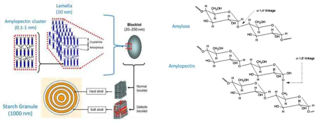
Figure 1.3- Internal organization of starch granules and molecular structure of the main components of starch - amylose and amylopectin (adapted from 8,11)... 6
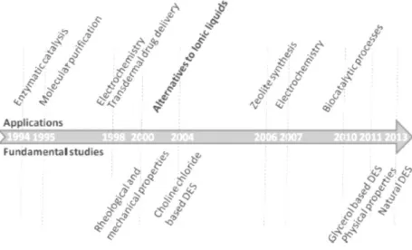
Figure 1.4- Synthesis of L,L-lactide and poly(L-lactic acid) (PLLA)………... 7 Figure 1.5- General synthesis of poly-ε-caprolactone (PCL) via ring opening polymerization... 8 Figure 1.6- Chemical structures of the most common anions and cations that constitute ILs……... 11 Figure 1.7- Schematic binary phase diagram of a eutectic system with two components. The point where the two liquidus and solidus boundaries meet is called the eutectic point…………... 12 Figure 1.8 - Historical perspective of the developments in the DES field, together with some applications of DES 61... 13
Figure 1.9- Phase diagram of a pure substance (adapted from 66)... 15
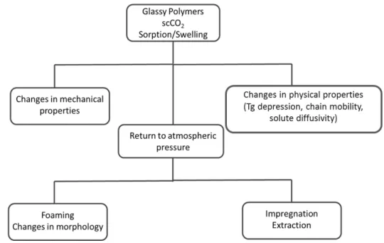
Figure 1.10- General scheme of the effects of scCO2 foaming in polymers (adapted from 75)... 18
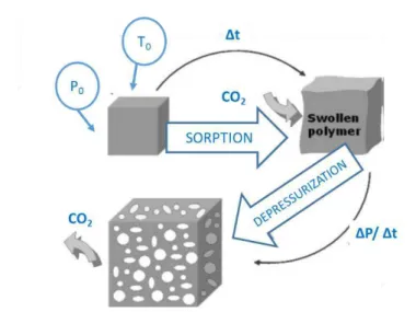
Figure 1.11- Schematic representation of the scCO2 foaming of a polymeric
material... 19 Figure 2.1- Schematic representation of the SCF foaming process of a polymer (adapted from 81)... 27
Figure 2.2- Different signals produced by the interaction of the high energy electron beam and a sample... 30 Figure 2.3- Karl-Fischer Coulometer (adapted from 90)... 33
Figure 2.4- Chemical Structure of Nile Red 92... 34
Figure 2.5- Typical DSC thermogram, registering different transitions (glass transition, melting and crystallization) with the associated temperatures Tg, Tm and Tc (adapted
from 99)... 36
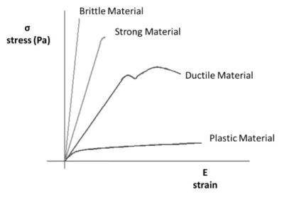
Figure 2.6- Examples of some types of materials according to their Young’s Modulus (adapted from 101)... 37
Figure 2.7 – Typical shear rate vs. shear stress curve obtained in rheology measurements and examples of the different fluid behaviour; shear thickening, Newtonian and shear thinning 107... 38
xx
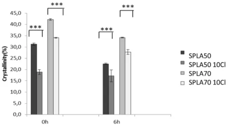
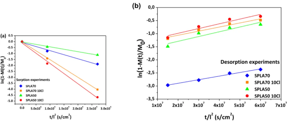
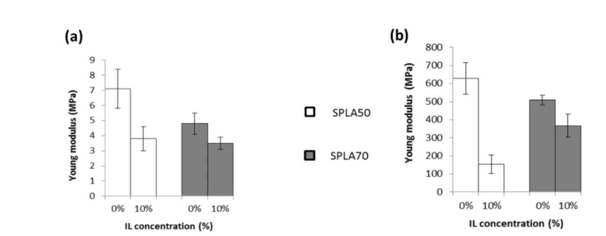
Figure 3.5- SEM micrographs of SPLA50 and SPLA50 10Cl, submitted to SCF foaming for different soaking times. ……… 52 Figure 3.6- Micro-CT analysis of the polymers studied..……….. 52 Figure 3.7- Porosity dependence on soaking time for SPLA polymers doped with [BMIM]Cl. Asterisks are referent to statistical analysis.………... 53 Figure 3.8- Crystallinity of the different samples under study, before and after the foaming process (soaking time of 6 hours)..………. 54 Figure 3.9- Sorption curves for samples under study.……….. 55 Figure 3.10- Representation of 𝑙𝑛(𝑀(𝑡) 𝑀⁄ )0 vs. 𝑡 𝑙⁄ 2 for the different sorption experiments carried out.………... 56 Figure 4.1- Effect of IL presence and IL concentration in the Young’s modulus of SPCL matrices in compressive mode (a) and tensile mode (b).……… 66 Figure 4.2- SEM and micro-CT 2D images of the cross section of the foamed samples. It must be noted that the SEM images of 10AcF, 10ClF and 30ClF have a scale of 200 µm and
the SEM images for SPCLF and 30ACF have a scale of 500 µm.………... 66
Figure 4.3- FTIR. ATR spectra of SPCL (a), 10Ac (b), 10Cl (c), 30Ac (d) and 30Cl (e)………... 68 Figure 4.4- DSC thermograms of the samples under study; Melting (endothermic) and crystallization (exothermic) process are clearly observed (a), scale up of the glass transition region obtained after annealing at -70 oC (b), clear vision of the melting peak
obtained in the second heating ru70n (c), scale up of the glass transition region for IL [BMIM]Ac (d)………... 70 Figure 4.5- Thermograms for samples submitted to SCF foaming. Melting and crystallization are observed (a), clear vision of Tg detected after annealing at -70 oC (b),
detailed vision of the melting in the subsequent heating run (c).……….... 71 Figure 4.6- Conductivity spectra of SPCL and SPCL samples doped with IL; isothermal curves collected at -80 oC (a), 0 oC (b), -80 oC after SCF foaming (c) and 0 oC after foaming
(d). All spectra were collected in the presence of residual amounts of water... 73 Figure 4.7- Representation of the imaginary part of the dielectric modulus; at 1 MHz (a), for the different samples and ILs (in logarithmic scale to allow comparison of data that varies several order of magnitude), SPCL before and after SCF foaming at 1 KHz (b), temperature dependence of ILs, at lower frequency (100 Hz) before and after heating to 120 oC (c)... 74
Figure 5.1- Thermograms for different NADES (after water removal) and corresponding POM micrographs; gluc:ta (1:1) (a), ca:gluc (1:1) (b). The inset in Figure 5.1 (a) shows the effect of water presence in the Tg and its subsequent removal.………... 85
Figure 5.2- Thermogram for NADES ChCl:xyl (3:1) (after water removal) with the corresponding POM microphotographs... 86 Figure 5.3- Microphotographs taken by POM at 25 oC at a magnification of 40x of
ChCl:xyl (3:1) (a) and ChCl:ca (1:1) (b)..………... 86 Figure 5.4- Isotherms of conductivity dependence with frequency, for the NADES ca:suc (1:1)... 89 Figure 5.5- Temperature dependence of the pure conductivity, σdc, of NADES. ChCl:xyl
xxi
Figure 5.6- ENR values of the NADES under study, and also for IL [BMIM]BF4 (included for
comparison)..………... 92 Figure 5.7- Influence of the water content in the nile red absorbance spectrum in the visible region, and in the ENR value.………... 92
Figure 5.8- Flow curves for (a) ca:suc (1:1) and (b) ChCl:ca (1:1), at 23 oC. Open symbols
refer to viscosity and closed symbols to shear stress………... 93 Figure 6.1- Results obtained for SPCL doped with various NADES, in terms of Young’s Modulus (bars) and elongation ate break (bullets) values. Results for undoped SPCL and SPCL doped with two imidazolium based ILs are included for comparison.………... 104 Figure 6.2- Effect of the pressurization and depressurization on the SCF foaming process of SPCL………... 105 Figure 6.3- Effect of pressurization and depressurization on the SCF foaming process of SPCL doped with NADES gluc:ta (1:1).……….... 105 Figure 6.4- SEM and micro-CT images of the SPCL+NADES materials, after SCF foaming…………... 106 Figure 6.5- Schematic of the preparation of ChCl:ma (1:2) and menthol:ibuprofen (3:1) THEDES. The final result can also be observed, ChCl:ma is liquid above ca. 70 oC and
xxiii
List of Tables
Table 1.1- Critical temperature and pressure of common SCFs (adapted from 66)... 15
Table 3.1- Listing of the SPLA polymers prepared.………... 44 Table 3.2- FTIR characteristic peaks of starch, PLA and [BMIM]Cl.……….. 48 Table 3.3- Thermal properties obtained by DSC for all the polymers under study………... 49 Table 3.4- Summary of the mechanical properties of the polymers studied………... 51 Table 3.5- Sorption degree, apparent sorption and desorption coefficients, for the samples under study.………... 55 Table 4.1- Prepared samples of SPCL and SPCL+IL and references... 62 Table 4.2- Results for the mechanical analysis of pure SPCL and SPCL doped with the two different ILs………... 65 Table 4.3- Porosity of the samples under study, foamed and unfoamed, obtained by micro-CT analysis... 67 Table 4.4- Characteristic FTIR peaks of starch, PCL and the ILs used in this work………….. 68 Table 5.1 – NADES prepared in this work, and the corresponding mole ratios of components and sample names.………... 80 Table 5.2- Water content and thermal properties of the NADES under study, degradation temperature (Td), melting temperature (Tm) and glass transition
temperature (Tg). The pure compounds are also included for comparison... 84
Table 5.3- Influence of the amount of water in the Tg value, measured by DSC; data
specific for the NADES ChCl:xyl (2:1)... 87 Table 5.4- Density of the NADES under study………... 88 Table 5.5- Conductivity data (σdc) for the NADES under study, at different
temperatures... 89 Table 5.6- Fit parameters obtained according to the VFT law for the conductivity (eq. 5.5)... 91 Table 5.7- Influence of the water content of ChCl:xyl (2:1) wavelength of maximum absorption (λmax)of nile red, and in the respective ENR value………... 93
Table 5.8- Apparent yield stress and viscosity of the NADES studied, at 23 oC……….... 94
Table 6.1- Summary of the DES prepared………... 100 Table 6.2- Water content of all the DES prepared………... 103 Table 6.3- Morphological parameters obtained for SPCL and SPCL+NADES foamed
samples... 107 Table 6.4- Micro-CT results for SPCL samples doped with different wt% of menthol:ibu
(3:1), and submitted to SCF foaming………... 115 Table 6.5- Results obtained for the modelling of the release of ibuprofen from foamed
and non-foamed SPCL matrices doped with 10 and 30 wt% of menthol:ibu (3:1) (NF
xxv
Abbreviations, acronyms and symbols
% percent
∆𝐻𝑚 melting enthalpy
∆𝐻𝑚0 standard melting enthalpy
γ̇ shear rate
𝑀𝑡0 cumulative amount of drug released at time 𝑡0
𝑀′(𝜔) real part of the dielectric modulus function
𝑀′′(𝜔) imaginary part of the complex modulus function
𝑀∗(𝜔) complex dielectric modulus function
𝑀0 mass of diffusing substance at equilibrium
𝑀∞ absolute cumulative amount of drug released at infinite time
𝑋𝑐 crystallinity degree
𝛿𝐶 𝛿𝑡⁄ concentration gradient
𝛿𝑃 𝛿𝑡⁄ depressurization rate
𝜀′(𝜔) real pat of the complex dielectric function
𝜀′′(𝜔) imaginary part of the complex dielectric function
𝜀∗(𝜔) complex dielectric function
𝜀0 dielectric permittivity in the vacuum
𝜂0 zero shear viscosity
𝜆𝑚𝑎𝑥 maximum wavelength
𝜎′(𝑓) real conductivity
𝜎′(𝜔) real part of the complex conductivity function
𝜎′′(𝜔) imaginary part of the complex conductivity function
𝜎∗(𝜔) complex conductivity function
𝜎0 yield stress
𝜎∞ high temperature limit of conductivity
[BMIM]+ 1-butyl-3-methylimidazolium cation
[BMIM]Ac 1-butyl-3-methylimidazolium acetate
[BMIM]BF4 1-butyl-3-methylimidazolium tetrafluoroborate
[BMIM]Cl 1-butyl-3-methylimidazolium chloride
∆𝑃 pressure drop
∆𝑡 time interval
µA microampere
µL microliter
µm micrometre
2D two dimensional
3D three dimensional
Ac- acetate anion
ATR attenuated total reflectance
B empirical parameter of Vogel-Fulcher-Tammann equation
ca. circa; approximately
CFA chemical foaming agent
xxvi
ChCl choline chloride
Cl- chloride anion
cm centimetre
CO2 carbon dioxide
-COOH carboxyl
DES deep eutectic solvent
DRS dielectric relaxation spectroscopy
DSC differential scanning calorimetry
E Young’s modulus
e.g. exempli gratia; for example
ENR normalized scale for solvent polarity relative to nile red
et al. et alli; and others
F foamed
FDA Food and Drug Administration
FTIR Fourier transformed infrared
g gram
GRAS generally recognized as safe
H2O water
HBD hydrogen bond donor
Hz Hertz
i.e. id est; in other words
I2 iodine
IBILs imidazolium based ionic liquids
ICVs/3B’s Life and Health Sciences Research Institute (ICVS), University of Minho, 3B’s Research Group - Biomaterials, Biodegradables and Biomimetics
IL ionic liquid
K degree Kelvin
keV kiloelectronvolt
KF Karl- Fischer
kg kilogram
KHz kilohertz
kN kilonewton
L span
LCA life cycle assessment
MHz megahertz
micro-CT micro-computed tomography
min minute
mm millimetre
mM millimolar
mm/min millimetre per minute
mol/kg mole per kilogram
MPa megapascal
NADES natural deep eutectic solvent
xxvii
nm nanometre
NSAID non-steroidal anti-inflammatory drug
oC degree Celsius
oC/min degree Celsius per minute
P pressure
Pa/s Pascal per second
PBS phosphate buffer saline
Pc critical pressure
PC polycarbonate
PCL poly(ε-caprolactone)
PE polyethylene
PEG polyethylene glycol
PET poly(ethylene terephtalate)
pH hydrogen power
PHA polyhydroxyalkanoate
PHB poly(β-hydroxybutyrate)
PLA poly(lactic acid)
PMMA poly(methyl methacrylate)
POM polarized optical microscopy
PP polypropylene
ppm parts per million
PS polystyrene
PVC polyvinyl chloride
R2 coefficient of determination
RTIL room temperature ionic liquid
s second
scCO2 supercritical carbon dioxide
SCF supercritical fluid
SEM scanning electron microscopy
SO2 sulphur dioxide
SPCL starch poly(ε-caprolactone)
SPLA starch poly(lactic acid)
SPLA50 starch poly(lactic acid) 50:50 SPLA70 starch poly(lactic acid) 30:70
T temperature
t time
T0 Vogel temperature
Tc crystallization temperature
Tc critical temperature
Td degradation temperature
Tg glass transition temperature
THEDES therapeutic deep eutectic solvents
TIPS thermally induced phase separation
Tm melting temperature
xxviii
UV/Vis Ultraviolet/Visible
VFT Vogel-Fulcher-Tammann
VOC volatile organic compound
wt% weight percentage
σDC direct conductivity
𝐶 concentration
𝐷 diffusion coefficient
𝐽 flux
𝐾 constant
𝑀(𝑡) mass of diffusing substance at time 𝑡
𝑓 frequency of the electric field
𝑖 imaginary number
𝑙 length
𝑛 release exponent
𝑡 time
𝑥 x axis
𝜂 viscosity
𝜋 Pi
𝜎 shear stress
1
Chapter 1
3
1.1. Bio-based polymers
A significant part of the world that surrounds us is based on polymers or polymeric materials, either because they are present in most products that we use daily or because they are present in nature.
Although polymers have long been used, their origin was not fully understood until the beginning of the 20th century. Most of the polymers used until then were from natural sources,
and it was not until the early 1900’s that synthetic polymers were prepared, such as Baekaland’s Bakelite resins obtained from phenol and formaldehyde 1–3. Still, scientists were not fully
informed about the nature of these materials, thinking they consisted of colloids. It was not until the 1920’s that Hermann Staudinger demonstrated that polymers are macromolecules. In the following decades, the synthetic polymers field fully bloomed 1.
Polymers have many applications, and synthetic polymers are those most used in industry. However, natural polymers are present in animals, in the form of hydrocarbons, proteins, nucleic acids, as well as in plants, playing the role of energy source, and also as important constituents of other organisms.
Polymers can have different forms, such as rubber and plastics that differ mostly in their mechanical and thermal properties 1. Of special interest are thermoplastic materials, which are
polymers that can be heated, shaped and moulded above a certain temperature, but return to their initial state when cooled.
The plastics sector represents one of the major applications for polymers in modern society. The production of plastics has been growing worldwide since the 1950’s, reaching a production of 288 million tons in 2012 4. In Europe, the main manufacturer of plastic materials
is Germany, with an overall production of 19.5 million tons in 2012, which resulted in a 25.1 billion euros revenue 4. The most used plastics are made from petroleum derived polymers,
namely polyethylene (PE), polypropylene (PP), polyvinylchloride (PVC), polystyrene (PS) and poly(ethyleneterephtalate) (PET), which have a wide range of applications, mainly in packaging and in construction (Figure 1.1) 4.
It is interesting to note that approximately 7% of the total amount of petroleum produced is used in the production of plastics. This means that this growing and profitable industry is mostly dependent on a limited resource, which raises concerns about the long debated energy crisis. Recycling alone cannot solve the petroleum dependence, since it is known that petroleum-based plastic materials are not easy to transform or to degrade in the environment 5. Also, almost 50 % of the plastic waste that is produced in Europe is still landfilled
and not recycled 6.
One of the ways to decrease this petroleum dependence is to change the raw materials the plastics industry is based on, from petroleum derived polymers to bio-based polymers. This can have a true effect in modern societies, offering economic, ecological and social benefits 4,5.
Bio-based polymers can be defined as polymeric materials produced from renewable resources 7. Bio-based plastics in particular offer great advantages over common
4
a low production capacity, and a not fully developed processing technology for this kind of materials.
Figure 1.1- Main polymers used in the plastics sector, and their main applications (data for Germany, in
2012, adapted from 4).
The concepts of bio-based polymers and biodegradable polymers are often assumed to be the same. However there are major differences between them. A biodegradable polymer is a material whose physical and chemical properties undergo deterioration and which completely degrades when exposed to microorganisms, carbon dioxide (aerobic process), methane (anaerobic process) and water (aerobic and anaerobic process).
In this sense, bio-based polymers can be biodegradable, as in the case of poly(lactic acid) (PLA), starch or polyhydroxyalkanoates (PHAs), or non-degradable, as in the case of biopolyethylene. Nevertheless, polymers can be derived from non-renewable resources, and still be biodegradable such as poly(ε-caprolactone) (PCL) 7.
The first bio-based polymers that were used were derived from agricultural feedstocks, but nowadays they are the result of biotechnology findings, since they can be produced by bacterial fermentation of renewable resources 7. The class of natural bio-based polymers also
comprises naturally occurring polymers, such as proteins and polysaccharides (starch, cellulose, chitin, collagen, and others).
The main ways to produce bio-based polymers using renewable feedstocks are:
1) using natural bio-based polymers with partial modifications to meet requirements (e.g. starch);
2) producing bio-based monomers by fermentation or conventional chemistry, and then proceed with the polymerization (e.g. PLA);
3) producing bio-based polymers directly from bacteria (e.g. PHA)
5
Figure 1.2- Bio-based polymer categories and production processes (adapted from 7).
Bio-based polymers have found many applications. Bio-based plastics were first introduced in the market in the 1980’s, mainly for packaging and agricultural applications.
In the following decade, the development of biodegradable products with improved properties took place, but the fact that some of these materials were petroleum derived materials meant that the main problem was not being addressed. It was not until the late 1990’s that the bio-based plastic community showed interest in renewable materials 4.
Today bio-based and biodegradable materials are attracting a lot of attention. An example of such materials is starch and various aliphatic polyesters. They can be classified according to the constituent monomers, as PHAs with the general structural formula HO-R-COOH, or poly(alkylene dicarboxylate)s, and are subdivided in α-, β- and ω-hydroxy acids, according to the position of the hydroxyl (–OH) group relative to the carboxylic (–COOH) end group.
Aliphatic polyesters have been used in this work, together with starch. A brief review of the properties and applications of these polymers is given in the next sections.
1.1.2. Starch and starch-based polymers
As it was referred earlier, one of the strategies that can be used to substitute petroleum derived polymers is to use bio-based (and if possible biodegradable) polymers.
Starch is a biodegradable polymer that fulfills these requirements, mainly because it is easy to obtain from natural sources, is one of the most abundant biopolymers worldwide and is very cheap 8. Approximately 7 million tons/year of starch are produced in Europe 9. It is present
in many plants and tubers, such as corn, wheat, rice, barley and potato.
Starch is produced by green plants for energy storage, in highly organized structures known as starch granules, located in plant cells. Starch is mainly composed by two types of molecules, namely linear and helical amylose and branched amylopectin. Amylose is an α -D-(1→6)-glucan, and amylopectin is a highly branched α-D-(1→4)-glucan with α-D-(1→6) linkages in the branch points 10. Figure 1.3 represents the organization of the starch granules, as well as
6
Figure 1.3- Internal organization of starch granules and molecular structure of the main components of
starch - amylose and amylopectin (adapted from 8,11).
Usually starch contains ca. 20-25% of amylose and 75-80% of amylopectin, but this is very dependent on the plant source. Starch is very hydrophilic, although its water content is highly dependent on the starch source, and also on the relative humidity at storage conditions
10.
Irrespective of its origin, starch is insoluble in cold water, but when heated, starch granules swell, and amylose and amylopectin leach out until the granules break down into a mixture of polymers in solution, which is known as the process of gelatinization 10. The ratio
between amylose and amylopectin present in starch will ultimately dictate most of its physical properties.
One of the problems of using starch is that it has limited processability, since it is very difficult to mold and transform. This is due to the fact that starch is semi-crystalline and there is also the possibility of the occurrence of retrogradation. This phenomenon consists in a natural increase of crystallinity over time, which leads to the increased brittleness of starch 7. Also, and
similar to other natural-based polymers, starch has high melting temperatures, often higher than the degradation temperature 12. Because of this, native starch is not used directly 8.
One way to increase starch processability is to produce thermoplastic starch (TPS). TPS is obtained by casting aqueous dispersions containing starch, water and soluble plasticizers. On an industrial scale TPS is mainly produced via extrusion. The plasticizer (which can be for example glycerol, sucrose, urea or stearic acid) destroys the starch granules by breaking the inter- and intramolecular hydrogen bonds that hold the chemical structure of starch, achieving depolymerization 10. The plasticization also helps to overcome the brittleness of starch through
the softening of the structure via increased mobility of the macromolecular chains, allowing the polymer to be processed at lower temperatures.
7 1.1.3. Starch-based polymer blends
Another method to ease the processability and performance of starch is to modify its structure, either by blending, derivation, or graft copolymerization.
The blending of starch with biodegradable polymers, such as aliphatic polyesters, is common. Some of the most used polyesters for this purpose are PLA and PCL. In this work, two different starch-based materials were used, namely starch/poly(lactic acid) (SPLA) and starch/poly(ε-caprolactone) (SPCL), that will be discussed in the following sections.
1.1.3.1. Poly(lactic acid) (PLA)
An example of a poly(α-hydroxy acid) is PLA. Its basic unit is the monomer lactic acid. It can be obtained via bacterial fermentation from corn starch or sugars from renewable resources
7. PLA can be synthesized from lactic acid (L- or D- enantiomer) by a polycondensation reaction,
or by ring-opening polymerization of the lactide monomer (Figure 1.4).
Figure 1.4- Synthesis of L,L-lactide and poly(L-lactic acid) (PLLA).
PLA has good transparency, a glossy appearance, high rigidity and the ability to tolerate various types of processing conditions. This makes PLA a good candidate to replace synthetic polymers such as PET, PS or polycarbonate (PC). The main drawbacks with its use are related to a relatively high cost, and to a glass transition temperature (Tg) of 60oC, which limits
processability (poor modifiability and poor mechanical ductility) 13. The glass transition is a
second order phase transition that occurs over a temperature range within which Tg is defined.
Bellow Tg, the polymer is hard and brittle, and above Tg it is moldable and soft.
There are several methods to overcome these processing limitations, such as the physical modification of PLA by blending and plasticization. Polymer blending has proved to be an effective and simple method to obtain new materials without having to synthesize new polymers 7,13. There are examples of biodegradable polymers that have been blended with PLA,
8
chitosan or starch. These blends resulted in materials with improved processability without sacrificing the biodegradability of PLA. Plasticization is another way to modify PLA, and is achieved by adding components (plasticizers) to the polymer so as to lower the Tg of the
polymer, increasing its ductility and “softness”. PEG, glycerol ad other organic based components have been used as plasticizers for PLA, resulting in PLA with improved processability.
PLA is a polymer that finds numerous applications in food packaging, membranes for the automotive industry, and even in textiles. Because PLA is a Food and Drug Administration (FDA) approved polymer, it is also applied in the biomedical field, for sutures, drug delivery devices, vascular grafts, artificial skin and orthopedic implants 9,14,15.
1.1.3.2. Poly(ε-caprolactone) (PCL)
PCL is an aliphatic polyester belonging to the poly(ω-hydroxy acid) family, and can be prepared by the ring-opening polymerization of ε-caprolactone using various catalysts (Figure 1.5), or via free radical ring-opening polymerization with 2-methylene-1-3-dioxepane.
PCL is a hydrophobic, semi-crystalline polymer with a low melting temperature (Tm=
59-60 oC), which makes it a polymer that can be easily moulded and shaped 16. It is biodegradable
(although at low rates), soluble in some organic solvents, such as chloroform and dichloromethane, and insoluble in ethanol, petroleum ether and diethyl ether 16. Its exceptional
biocompatibility together with the fact that it is also an FDA approved material, have led to applications in the biomedical field with very good results 16. The fact that this polymer exhibits
high permeability to many drugs and that it is excreted from the body once bioresorbed, makes it excellent for use in drug delivery systems, although its slow biodegradation rate makes it more suitable for long-term drug delivery purposes 16. Also, PCL has found applications in dentistry, as
a good material for surgical sutures, wound dressings and fixation devices, as well as for scaffolds
16.
9 1.2. Alternative solvents
In the processing or transforming of materials and polymers, whether they are petroleum-based or bio-based, the presence of a solvent is normally required, since the process is usually carried out in solution.
Until the last decades, aqueous or nonaqueous solvents such as organic solvents were used. When the scaling-up of a process is considered, the solvent choice plays a very important role, since it represents close to 85% of the mass utilization in a manufacturing process 17. If the
solvents to be used are organic, the emission of VOCs must be taken into account due to environmental and safety issues.
Since the birth of what is termed Green Chemistry, considerable efforts have been made to replace harmful solvents to the environment and general human health with “greener solvents” or in an ideal scenario, to implement solvent-free processes.
This is the basis of one of the 12 principles of green chemistry. These principles, first presented by Anastas and Warner in 1998 18, should be applied to the design of chemical
processes, so as to minimize environmental hazards:
“1) Prevention - it is better to prevent waste than to treat or clean up after it has been created. 2) Atom economy – synthetic methods should be designed to maximize the incorporation of all materials used in the process into the final product.
3) Less hazardous chemical synthesis – wherever practicable, synthetic methods should be designed to use and generate substances that possess little or no toxicity to human health or environment.
4) Designing safer chemicals – chemical products should be designed to affect their desired function while minimizing their toxicity.
5) Safer solvent and auxiliaries – the use of auxiliary substances (e.g., solvents, separation agents, etc.) should be made unnecessary whenever possible and innocuous when used. 6) Design for energy efficiency – energy requirements of chemical processes should be recognized for environmental and economic impacts and should be minimized. If possible, synthetic methods should be conducted at ambient temperature and pressure.
7) Use of renewable feedstocks – a raw material or feedstock should be renewable rather than depleting whenever technically and economically practicable.
8) Reduced derivatives- unnecessary derivatization (use of blocking groups, protection/deprotection, temporary modification of physical/chemical processes) should be minimized or avoided if possible, because such steps require additional reagents and can generate waste.
9) Catalysis – catalytic reagents (as selective as possible) are superior to stoichiometric reagents. 10) Design for degradation – chemical products should be designed so that at the end of their function they break down into innocuous degradation products and do not persist in the environment.
10
12) Inherently safer chemistry for accident prevention – substances and the form of a substance used in a chemical process should be chosen to minimize the potential for chemical accident, including releases, explosions and fires “ 18.
Green chemistry is also ruled by metrics that try to improve chemical process sustainability, such as the atom economy 19, the E-factor 20 or the mass efficiency and mass
productivity 21. The life cycle assessment (LCA) 22 together with the 12 principles is a good tool
to evaluate a process or product sustainability.
Following the new paradigm of Green Chemistry, solvents such as ionic liquids (ILs), deep eutectic solvents (DES) and supercritical fluids started to gain attention in several areas of chemistry. The processing of materials and bio-based polymers was no exception.
1.2.1. Ionic liquids
Ionic liquids (ILs) are regarded as a major breakthrough in the area of recyclable solvents. They can simply be defined as ionic compounds that possess a melting temperature below 100
oC 23, or even close to room temperature (room temperature ionic liquids, RTILs). ILs are salts
composed of ions, one or both of which are large, the cation having a low degree of symmetry, which reduces the lattice energy of the crystalline salt, leading to a lower melting point 24.
The field of ILs began with the discovery of ethylammonium nitrate, [EtNH3][NO3] by
Paul Walden in 1914 23, but it was not until the 1970-1980s that major advances emerged. The
potential of ILs arises from their physico-chemical properties, such as low vapor pressure, high electro-conductivity, high thermal stability and large liquid range 25.
Because ILs are composed of discrete cations and anions, there are numerous possibilities of combinations that can be engineered according to the final application. This is why ILs are also designated “tailor-made” solvents.
The most common ILs are based on imidazolium, ammonium, phosphonium, sulfonium pyridinium and pyrrolidinium cations. In the case of the anions, they can be fluorinated, such as hexafluorophosphate ([PF6]-), tetrafluoroborate ([BF4]-), trifluoroacetate ([CF3CO2]-) or
bis(trifluoromethylsulfonyl)imide ([NTf2]-), or non-fluorinated, such as tetrachloroaluminate
([AlCl4]-), nitrate ([NO3]-), acetate ([CH3CO2]-), chloride ([Cl]-) or bromide ([Br]-). Some of these
cations and anions are represented in Figure 1.6.
Although there is extensive research concerning many different IL families, the ones based on the imidazolium cation are the most studied 26.
ILs have found many applications, as solvents and reaction media 24, as catalysts 27–29, in
batteries and solar/fuel cells 30,31, for the capture of CO
2 30,32, among others.
ILs have also been applied in polymer sciences, playing multiple roles, in particular as solvents 33–35. Several authors reported the ability of ILs to solubilize and modify natural
polysaccharides, such as cellulose, lignocelluslosic materials, starch, chitin and chitosan 33–37. The
11
The term “green solvent” has been closely associated with ILs, mainly because of their negligible vapor pressure and non-flammability, which are clear advantages comparing to traditional VOCs. But it is clear that the “greenness” of ILs cannot be generalized, and they should not be called “green solvents” just because they are ILs 39,40. One of the aspects that
challenges the “greenness” of ILs is their environmental impact or, applying one of the green metrics, their E-factor. The syntheses of ILs implies extensive synthetic steps, the use of various reagents, and formation of by-products and/or waste 41. Another very important aspect that is
starting to be challenged is the eco and cytotoxicity, and biodegradability of ILs42.
Many authors consider three generations of ILs. The first generation ILs started to be studied in the 1960’s and comprised ILs with cations such as dialkylimkdazolium and alkylpyridinium, and anions such as chloroaluminate and other metal halides. They were characterized as air- and water-sensitive. To overcome these drawbacks, a second generation of ILs emerged in the 1990’s, where the ILs were formed by weakly coordinating anions, such as [BF4]- and [PF6]- 39. These ILs were extensively studied and characterized, and envisaged to be
successful alternatives in many processes, but the high cost of their synthesis hampered industrial applications. More recently, a third generation of ILs appeared, with ions that are more biodegradable and readily available, such as natural bases, amino-acids and natural occurring carboxylic acids 39.
Figure 1.6- Chemical structures of the most common anions and cations that constitute ILs.
Anions (fluorinated)
hexafluorophosphate tetrafluorobromi
de
tetrafluoroacetate bis(trifluoromethylsulfoyl)imide
Anions (non-fluorinated)
tetrachloroaluminate acetate chloride bromide
Cations
imidazolium ammonium phosphonium
12 1.2.2. Deep eutectic solvents
Deep eutectic solvents (DES) appeared alongside with the third generation of ILs. DES have been termed by Abbot et al. in 2003 43, and can be generally described as mixtures of
hydrogen bond donors (HBDs) and simple halide salts, with a melting point lower than that of each individual component, i.e. with a eutectic point 44. This happens due to the complexation
of the salt with the HBD, and charge delocalization.
Figure 1.7 represents the behavior of a binary eutectic. In order to form a eutectic system, the two components must be miscible in the liquid state, but completely immiscible in the solid state. In the binary system presented in Figure 1.7, the liquidus lines represent the temperatures at which homogeneous mixtures of A+B begin to crystallize, and above those lines the mixtures are completely liquid. The solidus line represents the temperatures at which mixtures of A+B start to melt, and below it the mixtures are completely solid. The enclosed areas represent liquid mixtures of A+B plus solid A, or liquid mixtures of A+B plus solid B. The point where the liquidus and solidus lines meet is called the eutectic point, corresponding to the eutectic composition. A liquid of this composition is the only one which, when cooled, does not yield pure A or pure B, but rather a solid mixture of A and B 45. The melting point depression is
directly related with the strength of the interactions between the system components.
Figure 1.7- Schematic binary phase diagram of a eutectic system with two components. The point where
the two liquidus and solidus boundaries meet is called the eutectic point.
13
DES share many characteristics with ILs, such as very low vapor pressure 46, although
they are not true ILs because either one of their components is nonionic or they comprise two nonionic species 44.
DES have been successfully employed for extraction due to enhanced solubility of certain compounds when compared with traditional solvents. Such is the example of bioactive molecules including benzoic acid, griseofluvin, danazol or itraconazole, which are drugs with poor solubility in water, but show much higher solubility in ChCl:urea and ChCl:malonic acid DES
47. DES have also been reported to be good extraction solvents for natural products 4849 , and
even for the extraction/dissolution of polysaccharides 50. Pioneering work concerning the use of
DES in biocatalysis was published in 1994 51–53. Lipases are one class of enzymes that are now
known to have improved catalytic activity in DES 54. DES have been reported also as useful
solvents for separation technologies 55, nanotechnology and even DNA assembling 56. DES also
have applications in the electrochemistry area 57,58, with special emphasis on metal
electrodeposition, as reported by Haerens et al. 59.
One of the areas that can benefit with the use of DES is the biomedical field, mostly due to the versatile, non-toxic, and biodegradable character of DES. They have already been reported to dissolve model drugs and at the same time increase their transdermal permeation and absorption, as in the case of a DES composed of menthol and camphor with dissolved ibuprofen 60. Stott et al. have also reported DES ability for uses in drug delivery, with various
compositions of ibuprofen combined with several terpenes 45.
As indicated, DES have improved properties compared to traditional solvents, and although they share many of IL characteristics, they are easier and cheaper to produce and in most cases non-toxic. Following a “green” chemistry philosophy, the development of even more sustainable and non-toxic DES followed, with the emergence of natural deep eutectic solvents (NADES) made from natural compounds. A small historical perspective of the DES field is given in Figure 1.8.
Figure 1.8 - Historical perspective of the developments in the DES field, together with some applications
14 1.2.2.1 Natural deep eutectic solvents
NADES are based on natural products (e.g. organic acids, amino-acids, choline chloride, sugars), which are abundant raw materials, biodegradable and have acceptable toxicity profiles
62. NADES were termed by Choi et al., following the discoveries that hypothesize that in living
organisms there is an alternative medium between aqueous and lipidic media. The existence of this alternative medium can explain a great number of biological processes, such as the biosynthesis of poorly water soluble metabolites and macromolecules in the aqueous environment of cells 63. According to the authors, these alternative media are composed of
natural metabolites like organic acids, amino-acids and sugars 63. Dai et al. later reported on a
set of natural compounds that were able to form NADES, and some of the physico-chemical properties and applications of the latter, which broadened the concept of NADES 62.
Examples of NADES that are found in nature are the flowers’ nectar, which was found to be a mixture of sugars (fructose-glucose-sucrose) and honey (a mixture of glucose and fructose)
62.
Several authors have recently been developing the concept of NADES, and detailed studies on the characterization and applications of NADES are now appearing in the literature
44,64.
As with DES, one of the applications envisaged for NADES is the extraction of natural compounds. Dai et al.65 have performed the extraction of phenolic compounds of different polarities, obtaining satisfactory results. Also, Paiva et al. have performed the extraction of phenolic compounds from green coffee beans using a series of different NADES 61. Extraction of
phenolic compounds with known anti-oxidant activity is of the utmost importance for the pharmaceutical industry, and a growing and profitable business, but it is often difficult to carry out in conventional solvents and even in ILs, due to their poor solubility, possible contaminations with trace amounts of solvent and the poor sustainability of the process. On the other hand, NADES present good properties for the extraction of bioactive compounds, NADES have tunable polarity and viscosity, which can be adjusted as a function of the extract under study.
NADES and DES are now seen as safer and more sustainable alternatives for a great number of chemical processes and applications. Their advantages have been highlighted, and are expected to boost and create tools that allow the practice of the 12 green chemistry principles.
1.3. Supercritical fluid technology
Supercritical fluid technology has also been used in the course of this work, in order to establish a new processing methodology for bio-based polymers.
A substance or compound in nature has four known physical states: solid, liquid, gas and plasma. Figure 1.9 illustrates the solid, liquid and gaseous domains, all of them well defined by phase boundaries. When a substance or compound is above its critical temperature (Tc) and
pressure (Pc) - critical point - it becomes a supercritical fluid (SCF). At the supercritical region the
15
viscosity, compressibility and mass diffusion coefficient 66. SCFs possess densities that enable
the solvation of solutes, and viscosities that facilitate mass transfer phenomena 66.
Table 1.1 gives Tc and Pc values for some common substances.
Figure 1.9- Phase diagram of a pure substance ( adapted from 66).
Table 1.1- Critical temperature and pressure of common SCFs (adapted from 66).
Fluid Tc (oC) Pc (bar)
carbon dioxide 31.1 73.8
water 374.1 221
ethane 32.5 49.1
propane 96.8 42.6
cyclohexane 279.9 40.3
methanol 240.0 79.5
ethanol 243.1 63.9
acetone 235.0 47.6
The most commonly used SCF is scCO2, since it has critical parameters that are easily
attained, especially a relatively low critical temperature that makes it possible to work with sensitive compounds, such as pharmaceuticals or bioactive molecules. Also, CO2 is considered
to be nontoxic, nonmutagenic, nonflammable and thermodynamically stable, having also a GRAS status (generally recognized as safe solvent) 66,67. Because CO
2 elimination is easy (by
depressurization or pressure drop), its use is more widespread. Supercritical CO2 leaves no
residues, contrary to the use of VOCs. Upon completion of an application, CO2 can be recovered
and reused, with no contributions to the greenhouse effect, and thus scCO2 is also regarded as
![Figure 3.7- Porosity dependence on soaking time for SPLA polymers doped with [BMIM]Cl](https://thumb-eu.123doks.com/thumbv2/123dok_br/16484800.732686/81.892.158.723.148.396/figure-porosity-dependence-soaking-spla-polymers-doped-bmim.webp)