Francisco Manuel de Oliveira Esteves
Licenciado em Ciˆencias da Engenharia Electrot´ecnica e deComputadores
Implementation of a Cognitive Radio
Access System
Disserta¸c˜ao apresentada para obten¸c˜ao do Grau de Mestre em Engenharia Electrot´ecnica e de Computadores, pela Universidade Nova
de Lisboa, Faculdade de Ciˆencias e Tecnologia.
Orientadores : Rodolfo Oliveira, Professor Auxiliar, FCT/UNL
Lu´ıs Bernardo, Professor Auxiliar, FCT/UNL
J´uri:
Presidente: Doutor Paulo da Costa Lu´ıs da Fonseca Pinto, Professor Catedr´atico da FCT/UNL
Vogais: Doutor Rodolfo Alexandre Duarte Oliveira, Professor Auxiliar da FCT/UNL
Doutor Lu´ıs Filipe Louren¸co Bernardo,
Professor Auxiliar com agrega¸c˜ao da FCT/UNL Doutor Fernando Jos´e da Silva Velez,
Professor Auxiliar da Universidade da Beira Interior (UBI)
i
Implementation of a Cognitive Radio Access System
Copyright c Francisco Manuel de Oliveira Esteves, Faculdade de Ciˆencias e Tecnologia, Universidade Nova de Lisboa
“To invent, you need a good imagination and a pile of junk.”
Agradecimentos
Quero come¸car por agradecer ao meu orientador, o Professor Rodolfo Oliveira pela paciˆencia, dedica¸c˜ao, disponibilidade e amizade demonstradas ao longo desta disserta¸c˜ao. Quero tamb´em agradecer ao meu coorientador, o Professor Lu´ıs Bernardo, pela igual disponibi-lidade e dedica¸c˜ao demonstradas.
Agrade¸co aos meus colegas de laborat´orio e a todos os meus amigos pelos bons momentos passados, especialmente ao longo do per´ıodo de desenvolvimento desta disserta¸c˜ao e pelo seu contributo para a mesma.
Ao meu colega Ant´onio Furtado, cujo contributo foi essencial para esta disserta¸c˜ao, deixo o meu especial agradecimento.
Ao meu colega Jos´e Vieira, um agradecimento especial pela ajuda prestada na revis˜ao desta disserta¸c˜ao.
Quero agradecer aos meus av´os, Albino e Donz´ılia, por tudo o que fizeram e continuam a fazer por mim, pois ´e a eles que devo grande parte da minha educa¸c˜ao. Obrigado por todo o carinho, amor e dedica¸c˜ao que sempre me deram, independentemente do momento ou situa¸c˜ao. Para mim s˜ao pessoas com um valor incalcul´avel `as quais eu espero conseguir retribuir o que tˆem feito por mim.
Quero agradecer aos meus pais, que sempre me deram tudo, irm˜a e a toda a minha fam´ılia o apoio e carinho que sempre me deram ao longo dos anos e que fizeram com que eu sempre me sentisse feliz.
Quero deixar um agradecimento especial aos meus tios Jorge e Irene por me terem tratado como um filho e me terem ajudado sempre que precisei.
Aos meus primos, Tom´as, Salom´e e S´ılvia quero deixar o meu agradecimento pois s˜ao os melhores primos do Mundo!
Aos meus futuros sogros, nunca ´e demais agradecer por tudo o que tˆem feito por mim e pelo carinho que sempre me deram. Estiveram sempre dispon´ıveis para me ajudar no que fosse necess´ario e a fazer por mim o que fosse preciso independentemente da situa¸c˜ao. Nunca conseguirei agradecer o suficiente, por tudo o que fizeram e por me terem tratado como um filho.
Resumo
Actualmente, com o aumento do n´umero de dispositivos sem fios, o espectro de r´adio dispon´ıvel ´e cada vez menor. A grande maioria dos dispositivos sem fios, habitualmente denominados de dispositivos licenciados ou utilizadores prim´arios, devido ao facto de ope-rarem em bandas previamente licenciadas para o efeito, n˜ao s˜ao suficientemente dinˆamicos para se adaptarem a esta nova realidade. Dessa forma, s˜ao necess´arias novas pol´ıticas de aloca¸c˜ao de espectro que apresentem maior rendimento na utiliza¸c˜ao dos recursos dis-pon´ıveis.
Entre as solu¸c˜oes para o aumento de desempenho, encontram-se os sistemas de r´adio cognitivo. Estes dispositivos, tamb´em denominados de dispositivos n˜ao licenciados ou uti-lizadores secund´arios, s˜ao capazes de utilizar partes do espectro que durante algum tempo possam n˜ao estar a ser utilizadas pelos dispositivos licenciados. A introdu¸c˜ao destes dis-positivos nas redes actuais ´e o ponto de partida para a cria¸c˜ao de redes cognitivas onde os dispositivos licenciados continuam a usar normalmente os recursos da rede e os n˜ao licenciados s˜ao capazes de utilizar os espa¸cos livres no espectro.
Neste trabalho o software de controlo de uma placa de rede sem fios comum ´e modificado para o teste de alguns destes conceitos. Inicialmente, s˜ao efectuadas valida¸c˜oes no software a fim de se obter o controlo total do mecanismo de transmiss˜ao e recep¸c˜ao de dados. De seguida, o mecanismo de controlo da janela de conten¸c˜ao ´e testado e usado para controlar o d´ebito de dados e o accesso ao meio do dispositivo.
Na segunda parte deste trabalho ´e desenvolvido e implementado um protocolo para esti-mar a probabilidade de acesso de um utilizador prim´ario. Depois de v´arios testes pr´aticos e te´oricos ´e feita uma compara¸c˜ao entre os resultados de forma a caracterizar o seu desem-penho. Esta an´alise mostra como e com que n´ıvel de sucesso ´e poss´ıvel estimar a presen¸ca na rede de um utilizador prim´ario atrav´es de um ou mais utilizadores secund´arios.
Palavras Chave: Sistemas de R´adio Cognitivo, Controlo de Acesso ao Meio, Janela de Conten¸c˜ao, Probabilidade de Acesso, Utilizadores Prim´arios e Secund´arios.
Abstract
Over the last two decades we have observed a rapid increase of the number of wireless de-vices. This fact poses big challenges to solve, namely because the available radio spectrum is limited and is becoming scarce. The most part of the actual wireless devices, usually called licensed devices or primary users, due to the fact of being licensed to operate in a specific band, are unable to dynamically adapt to other bands. In consequence, new spectrum allocations policies are being implemented.
The cognitive radio systems are among the actual solutions to increase this performance. These devices, often called unlicensed devices or secondary users, are capable of using spectrum holes that are not being used by the licensed users for a brief period of time. The introduction of these devices to the current wireless networks will be the starting point for the creation of cognitive radio networks, where licensed devices still use the spec-trum normally and the unlicensed devices form the cognitive radio network that will take advantage of the spectrum holes freed, left by the licensed devices.
In this work, an open-source wireless driver for a commercial wireless network card is modified in order to test some of these concepts. First, some key validations are made in order to have a full control of the driver’s transmission/reception mechanism. After this validation, the driver’s contention window control mechanism is tested and used for controlling the data throughput and the device’s access to the medium.
In a second part of this work, a primary user activity estimation scheme is present. With this scheme, after several practical tests it is possible to establish a comparison between the protocol simulation results and the practical tests in order to evaluate its performance. This analysis assesses the level of accuracy of the estimation of the primary user presence, when done by one or more secondary users on the network.
Keywords: Cognitive Radio Systems, Medium Access Control, Contention Win-dow, Access Probability, Primary and Secondary Users.
Acronyms
ACK Acknowledgment
AMC Adaptive Modulation and Coding
AMM Alternative Mode Monitoring
AP Access Point
API Application Programming Interface
BSD Berkeley Software Distribution
CA Collision Avoidance
CCK Complementary Code Keying
CCTS Control-Channel-Clear-To-Send
CR Cognitive Radio
CR-ALOHA Cognitive Radio ALOHA
CR-CSMA Cognitive Radio Carrier Sense Multiple Access
CRN Cognitive Radio Network(s)
CRTS Control-Channel-Request-To-Send
CSMA Carrier Sense Multiple Access
CSMA/CA Carrier Sense Multiple Access with Collision Avoidance
CTS Clear-to-Send
CW Contention Window
DCF Distributed Coordination Function
DIFS Distributed Interframe Space
GUI Graphical User Interface
HAL Hardware Abstraction Layer
IMI Initial Mode Identification
LAN Local Area Network
MAC Medium Access Control
NS-2 Network Simulator v2
OFDM Orthogonal Frequency Division Multiplexing
PU Primary User
QAM Quadrature amplitude modulation
QOS Quality of Service
QPSK Quadrature phase-shift keying
RTS Request-to-Send
SCA Statistical Channel Allocation
SCA-MAC Statistical Channel Allocation Medium Access Control
SIFS Short Interframe Space
SNR Signal-to-Noise Ratio
SU Secondary User
UDP User Datagram Protocol
VAP Virtual Access Point
Contents
Agradecimentos vii
Resumo ix
Abstract xi
Acronyms xiii
1 Framework 1
1.1 Introduction . . . 1
1.2 Motivation . . . 2
1.3 Objectives and Contributions . . . 3
1.4 Structure of the Dissertation . . . 4
2 Related Work 5 2.1 Introduction . . . 5
2.2 Cognitive Radio Sensing Dimensions . . . 6
2.3 Sensing Architectures . . . 8
2.4 Sensing Techniques . . . 8
2.5 Cooperative Sensing . . . 10
2.6 CSMA and MAC in Cognitive Radio . . . 10
2.6.1 CSMA based MAC Protocols for Cognitive Radio Networks . . . 11
2.6.1.1 Rate-Distance Nature of Wireless Communications . . . 12
2.6.1.2 New CSMA based MAC Protocols . . . 13
2.6.1.3 Achievements . . . 15
2.6.2 Two-level MAC Protocols for Cognitive Ratio Networks . . . 15
2.6.2.1 Slotted CR-ALOHA and CR-CSMA Spectrum Access . . . 15
2.6.2.2 Slotted CR-ALOHA Operation Scheme . . . 17
2.6.2.3 CR-CSMA Operation Scheme . . . 18
2.6.2.4 Performance Analysis for CR-CSMA and slotted CR-ALOHA 19 2.6.3 SCA-MAC for Wireless Ad-hoc Networks . . . 20
2.6.3.1 SCA-MAC Operation Scheme . . . 21
2.6.3.2 Statistical Channel Allocation (SCA) . . . 23
2.6.3.3 Achievements . . . 24
2.7 Conclusion . . . 24
3 Madwifi Description and Validation 27 3.1 Introduction . . . 27
3.2 Madwifi Description . . . 27
3.2.1 Early History . . . 27
3.2.2 Driver Features . . . 29
3.2.3 Driver Software License . . . 30
3.2.4 Driver Version and LinuxR Environment . . . 30
3.2.5 Hardware Version and Specifications . . . 30
3.3 Madwifi Software Organization . . . 30
3.3.1 Net80211 Stack . . . 30
3.3.2 Ath . . . 31
3.3.3 HAL (Hardware Abstraction Layer) . . . 32
3.3.4 Rate Algorithms . . . 32
3.3.5 Madwifi Source Code Organization . . . 33
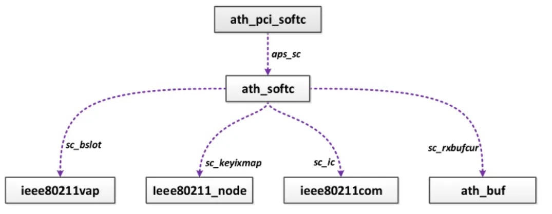
3.3.5.1 Main Data Structures Organization . . . 33
3.3.5.2 Net device . . . 34
3.3.5.3 Sk buff . . . 34
3.3.5.4 Ath softc . . . 35
3.3.5.5 Ieee80211vap . . . 35
3.3.5.6 Ieee80211 node . . . 35
3.3.5.7 Ieee80211com . . . 36
3.3.5.8 Ath buf . . . 36
3.4 Madwifi Driver Transmission/Reception Scheme . . . 36
3.4.1 Contention Window (CW) . . . 36
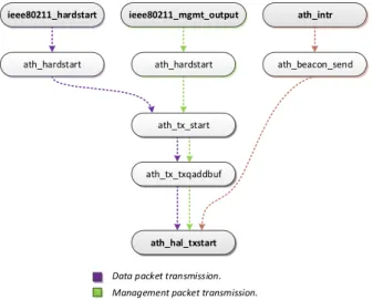
3.4.2 Transmission . . . 38
3.4.2.1 Data Frames . . . 39
3.4.2.2 Management Frames . . . 39
3.4.2.3 Beacons . . . 40
3.4.3 Reception . . . 40
3.4.3.1 Data Frames . . . 40
3.4.3.2 Management Frames . . . 41
3.4.4 Frame Sniffing (monitor mode) . . . 41
3.4.4.1 Outgoing Frames “Sniffing” . . . 42
3.4.4.2 Incoming Frames “Sniffing” . . . 42
3.5 Proposed Module for Validation of i/o (input/output) . . . 42
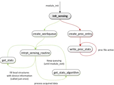
3.5.1 ath sensing module . . . 43
3.5.1.1 Workqueue and Sensing Routine . . . 44
CONTENTS xvii
3.6 Validation Results . . . 45
3.6.1 Data Transmission Application . . . 46
3.6.2 Data Reception Application . . . 46
3.6.3 Athstats . . . 47
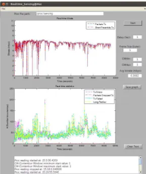
3.6.4 Real-time Proc File Analyser from the Proposed Module . . . 48
3.6.5 Gathered Data Analysis . . . 49
3.7 Conclusion . . . 51
4 Primary User Activity Estimation 53 4.1 Introduction . . . 53
4.2 Individual Medium Access Probability . . . 54
4.2.1 Single Node’s Access Probability . . . 54
4.2.2 Error and Collision Probabilities . . . 56
4.2.3 PU Access Probability Estimation . . . 58
4.3 Conclusion . . . 60
5 Performance Analysis 61 5.1 Introduction . . . 61
5.2 Madwifi’s Implementation . . . 61
5.2.1 Driver’s Sensing Module input/output . . . 62
5.3 Developed Applications . . . 63
5.3.1 PU Application . . . 65
5.3.1.1 PU Behavior . . . 65
5.3.2 SU Application . . . 66
5.3.3 Access Point Application . . . 66
5.3.4 Proc Reader/Writer Application . . . 67
5.3.5 Control Panel Application . . . 67
5.3.5.1 Node’s Transmission Control . . . 67
5.3.5.2 Node’s Proc Reader Control . . . 68
5.3.5.3 Live Graph Tool . . . 68
5.4 Final Test Environment and Network Setup . . . 68
5.4.1 Setup Parameters . . . 69
5.4.2 Testing Procedures and Data Gathering . . . 70
5.5 Performance Results . . . 71
5.5.1 Simulation Results . . . 72
5.5.2 Practical Results . . . 74
5.5.3 Comparative Analysis . . . 76
5.5.3.1 PU’s Activity Estimation Analysis . . . 76
6 Conclusions 79
6.1 Final Considerations . . . 79
6.2 Future Work . . . 81
Bibliography 82 Appendix 87 A Specific Driver’s Characteristics 89 A.1 Madwifi Frame Timings and Chosen Parameters . . . 90
A.2 Madwifi Source Code . . . 91
A.2.1 Installation and Configuration Bash Scripts . . . 91
A.2.2 Sensing Module . . . 91
B Validation Tools and Scripts 93 B.1 Contention Window Behavior - MatlabR Code . . . 93
B.2 athstats output analyzer - MatlabR code . . . 93
B.2.1 athstats analyzer: simulation duration - MatlabR code . . . 93
B.2.2 athstats analyzer: expected bit rate - MatlabR code . . . 93
B.2.3 athstats analyzer: noisy environment test - MatlabR code . . . 93
B.2.3.1 Noisy Environment Trace Files . . . 94
B.2.3.2 Noisy Environment Test Results . . . 94
B.2.4 athstats analyzer: faraday cage test - MatlabR code . . . 94
B.2.4.1 Controlled Environment Trace Files . . . 94
B.2.4.2 Controlled Environment Test Results . . . 94
B.3 Proc File Real Time Analyzer - MatlabR Code . . . 94
B.4 Test Applications - JavaR Code . . . 95
B.4.1 Data Transmission Application . . . 95
B.4.2 Data Reception Application . . . 95
C Test Applications and Scripts 97 C.1 Test Applications - JavaR Code . . . 97
C.1.1 SU Application . . . 97
C.1.2 PU Application . . . 97
C.1.3 AP Application . . . 98
C.1.4 Proc Reader/Writer Application . . . 98
C.1.5 Control Panel Application . . . 99
C.2 athstats output analysis - scripts, trace files and results . . . 100
C.2.1 Simulation Results Analysis . . . 100
C.2.1.1 MatlabR Scripts Code . . . 100
C.2.1.2 Trace Files . . . 100
CONTENTS xix
C.2.2 Practical Tests Results Analysis . . . 100 C.2.2.1 MatlabR
List of Figures
2.1 Cognitive Radio Network and Primary Users Network coexisting. . . 13 2.2 Four-way handshake process. . . 13 2.3 MAC frame structure for the two-level OSA strategy [Won11]. . . 16 2.4 Operation scheme for slotted CR-ALOHA. . . 17 2.5 Operation scheme for CR-CSMA. . . 18 2.6 Operation scheme for SCA-MAC. . . 21 3.1 Madwifi driver structure. . . 31 3.2 Madwifi driver main data structures with the respective pointers. . . 33 3.3 Sk buff structure and the relation with the packet. . . 34 3.4 HAL Contention Window (CW) restriction. . . 37 3.5 Madwifi driver transmission scheme. . . 38 3.6 Madwifi driver post transmission scheme. . . 39 3.7 Madwifi driver reception scheme. . . 40 3.8 Madwifi driver sniffing mechanism (monitor mode). . . 42 3.9 Initialization process for the proposed module. . . 43 3.10 Unload process for the proposed module. . . 44 3.11 Transmission throughput comparison between the environments (a) and (b). 47 3.12 Reception throughput comparison between the environments (a) and (b). . 48 3.13 Proc file analysis application during one transmission (noisy environment). 49 4.1 Markov chain illustrating the backoff process. . . 54 5.1 Proc file system used by the ath sensing module. . . 62 5.2 Proc file system writing from user’s space toath sensing module. . . 63 5.3 starting point of the Test framework with the SU, PU and AP nodes. . . . 64 5.4 Proc file reader/writer running in each node. . . 64 5.5 PU’s access scheme based on the exponential calculation. . . 65 5.6 Complete diagram of the test framework and network. . . 69 5.7 Simulated SUs’ ˆPS accordingly the PU’s time occupancy and the CW. . . . 72 5.8 SUs’ success probability depending on the PU’s access probability. . . 73 5.9 SUs’ success probability depending on the CW value. . . 73
List of Tables
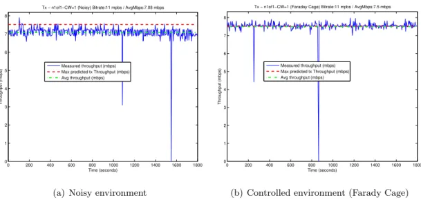
3.1 Maximum theoretical vs. real throughput according several CW values in a noisy and in a controlled radio environment (Faraday Cage). . . 50
Chapter 1
Framework
1.1
Introduction
In the last few years, the World has been watching the exponential growth of the number of wireless devices and networks. Nowadays, almost every house, public space or govern-ment facility have wireless networks, and they are used simultaneously by many devices. These networks are used to provide internet access, data transfer and many other services, therefore, they have a huge role in the actual society.
This brings a new concern, that has been neglected since the early days of the wireless networks, due to the lack of wireless devices, the radio spectrum occupancy. Every device requires permanent network access with good quality and with a high transmission bit rate. The increasing demand of radio spectrum access will eventually lead to a congestion, resulting in an unfair access opportunity for all devices and no possibility of assuring the required quality of service (QOS).
The available spectrum frequencies are becoming scarce and the traditional radio devices are unable to use the available spectrum in an efficient manner due to their rigid archi-tecture and incapacity to adapt to new radio spectrum characteristics. These devices, denominated licensed devices or primary users (PUs), leave several “gaps” in radio spec-trum during their operation, making the radio specspec-trum usage efficiency not as good as it could be. To fully increase the efficiency, these gaps become the target of cognitive radio devices, denominated non licensed devices or secondary users. This allows the accom-modation of a large number of devices in the same radio spectrum, providing an overall
increase of the usage efficiency.
Cognitive radio devices differ from the traditional radio devices due to the ability of “sens-ing” the spectrum or being able to know which part of the spectrum is free to be used without causing interference to the licensed users.
Sensing is the main characteristic of these devices, because they are able to have a much higher knowledge of the radio spectrum than the traditional radio devices. This feature allows the device to know how the radio spectrum is and when it is occupied.
The cognitive radio devices must be able to transmit information using several free fre-quencies bands without causing any interference to the licensed devices.
Unlike the traditional radio, which is built almost entirely by hardware, the cognitive radio is constituted mainly by software, which confers the device an intelligence capability that will be determinant, to allow learning and evolving during the device functioning.
The cognitive radio is probably the future of radio devices, because the natural trend is to require much more efficiency in spectrum usage to allow an higher number of devices to establish communication with good quality of service, making possible the coexistence of non licensed and licensed devices on the same band.
1.2
Motivation
The cognitive radio devices must operate using the available radio spectrum frequency bands, which constitutes a difficult task since the licensed users (Primary Users) to use the spectrum, must be kept free of interference. This, along with the ability of sensing the spectrum are the main challenges for the cognitive radio.
The sensing is performed using several techniques, but the energy detector is the most common one, which consists in the comparison of the energy of the detected signal with a threshold value in order to determine if there is any device transmitting at that instant. The threshold value can be defined using several methods but its efficiency is always questionable. Higher levels of interference will decrease its accuracy while increasing the probability of false alarm of the PUs.
1.3. OBJECTIVES AND CONTRIBUTIONS 3
activity of the primary users.
The IEEE 802.11 standard is the most common standard for data wireless communications. Since this technology is present in almost all mobile devices, it becomes one of the main motivations for this work, whereas the massive adoption of this standard can be used as a way to develop cognitive radio systems.
The contention mechanism adopted in IEEE 802.11 standard is used in this work to indirectly give us a measure of PU’s activity. This fact motivates some changes that could be made in order to achieve better network performance. The possibility of estimating the activity of PUs through the used of a contention-based protocol in the SUs constitutes the main motivation for this work.
1.3
Objectives and Contributions
The creation of a contention based network to act as a secondary network is one of this work’s objectives. This network will be formed by several secondary nodes that will es-timate the primary nodes’ activity. To achieve this goal it was decided to use the IEEE 802.11 protocol and it was chosen the Madwifi software driver. Several steps must be taken starting with the understanding of the IEEE 802.11 wireless driver structure (Chapter 3), the Madwifi, which is used to control the wireless devices. Having a clear notion how it works and how it is structured, will allow the needed modification to implement new protocols and therefore the creation of a cognitive access system.
The next step will be validating the results obtained through the driver statistic mecha-nism, in order to confirm the frame timings that are needed to setup each transmission. After this, the primary user (PU) estimation protocol must be implemented through a theoretical approximation (Chapter 4) and its performance tested for validation in Chap-ter 5 by establishing a comparison between the theoretical and practical results.
1.4
Structure of the Dissertation
This dissertation is split in six Chapters and three appendixes. The first Chapter (“Frame-work”), introduces the problems addressed in this work and identifies the main objectives of the work.
The second Chapter (“Related Work”) refers the actual state of the art for the cognitive radio networks. An approach is made to the cognitive radio sensing methods and the cur-rent protocols that were proposed for this technology, when applied to the IEEE 802.11 networks.
The third Chapter (“Madwifi Description and Validation”) describes the structure of the Madwifi IEEE 802.11 wireless driver used for implementing the proposed cognitive access system. The driver’s performance validation represents the last part of this chapter. The fourth Chapter (“Primary Users Activity Estimation”) is dedicated to the PU activity estimation. The estimation is meant to be done by the SUs on the network. This chapter describes the theoretical approach behind the proposed estimation scheme.
The fifth Chapter (“Performance Analysis”) explains how the PU activity estimation was implemented and characterizes the obtained results from both simulation and practical results. A performance analysis is done for all test results and a comparison of all consid-ered scenarios is also presented.
The sixth Chapter (“Conclusions”) describes the results obtained with the proposed cog-nitive access system. A resume of all the development and a plan for future work ends the description.
The Appendix A explains how the IEEE 802.11 frame timings were obtained for the Mad-wifi driver and how the throughput is estimated for each transmission.
The second Appendix, the Appendix B, contains the source code of all applications used in the results validation (Chapter 3), such as the Matlab application, scripts and all java applications.
Chapter 2
Related Work
2.1
Introduction
In the last few years, the growth of wireless networks has been exponential. Today is fairly common to have several wireless networks operating in the same location. These networks can be infra-structured or infrastructure-less (ad-hoc). The infra-structured network is the most common type of wireless network, although,ad-hocnetworks are becoming more usual and their number is increasing very rapidly due to the growth of mobile devices with wireless networking capabilities.
With such a high number of wireless networks and devices it is very important to grant good performance and a very low error rate in each transmission between devices and a fair access policy for every device. This brings a huge concern, because the wireless spectrum is reaching the limit in terms of occupancy, so it is very important to implement mechanisms capable of managing the spectrum occupancy, granting a fair access policy to every device and minimizing the number of collisions or transmission errors.
The most common wireless devices are equipped with radio transceivers implementing the 802.11 DCF standard [IEE07]. These devices are unable to dynamically manage the spectrum occupancy because they are statically allocated to a given frequency band. The main goal of this work is to use the ”gaps” in the spectrum freed by licensed users to transmit information and therefore, reach a better spectrum occupancy and efficiency. To take advantage of these ”gaps” in the spectrum, a deeper knowledge of the spectrum is needed from the non-licensed devices that will use them. This knowledge is acquired
through the sensing mechanism implemented in the device. By other words, sensing in a radio environment, is the ability of having a notion of the spectrum occupancy. The most common sensing method is the energy-based, and is present in the majority of the IEEE 802.11 radio devices. A deeper knowledge of the spectrum occupancy will be helpful since it can be translated in a more efficient network resources usage.
The time spent in the spectrum sensing is also one of the main concerns. If a node spends too much time to decide about the occupancy state of the channel, the decision can be easily outdated and the practical usage of the decision can be highly inefficient
A Cognitive Radio (CR) is a non-licensed device that is capable of sensing the radio environment and decide which are the best transmission parameters for the current radio environment, as well the frequency in the available spectrum to be used. CR devices are defined by the capability of sensing the surrounding environment and having a notion of the spectrum occupancy. Using that information, CR devices become able to make adjustments for their transmission parameters in order to be more efficient.
There are two kinds of users in a cognitive radio network (CRN). The primary users (PUs) or licensed users, and the secondary users (SUs) or non-licensed users. The PUs are the owners of the spectrum and they should use the spectrum whenever they want. The SUs, can use the spectrum in an opportunistic way and must reduce the level of interference caused to the PUs. The CR device can only take advantage of the unused part of the spectrum or a specific frequency channel used by a PU when it is free, but only for a brief period of time.
This chapter introduces the most knownsensingtechniques at a physical level and Medium Access Control (MAC) protocols for cognitive radio networks (CRNs) in order to introduce the work already done in this field.
2.2
Cognitive Radio Sensing Dimensions
There are many dimensions of sensing in CR that can be taken into consideration. These dimensions are related with the domain that is selected to detect the presence of licensed users.
2.2. COGNITIVE RADIO SENSING DIMENSIONS 7
• Frequency - The frequencies available in the radio spectrum can be used by CR devices to achieve a better spectrum usage. The main idea is to take advantage of available bands in the radio spectrum [Yuc09], [Mar10], [Hay10].
• Time- In the same band there are also time opportunities, because the band is not used continuously in time-domain and there will be also unoccupied ”gaps” that can be explored by SUs [Yuc09], [Hay10], [Cha10].
• Geographical space - Based on location (latitude, longitude, and elevation) and distance of PUs, CR devices can take advantage of the the path loss to reuse the bands occupied by PUs. The channel occupancy is determined by the interference level at a given position and is only valid for a given instant of time. When inter-ference is detected, the CR device assumes that a primary is transmitting [Hao09], [Yuc09], although, there is always a great concern about the hidden cognitive termi-nal problem .
• Code- It is possible to perform simultaneous transmissions if the SUs uses a different code than the one in use by the PU [Yuc09], [Lo10]. Although, it is extremely important to grant the usage of an orthogonal code to avoid any type of interference with the PU as well the channel occupancy in terms of codes at the moment of the transmission. This will also require a good time synchronization between the SUs and the PUs.
2.3
Sensing Architectures
There are two types of sensing architectures. The single-radio and the dual-radio archi-tecture.
• Single-radio - This scheme uses a single radio to sense and transmit information. The downside of this architecture is that a time period is allocated for spectrum sensing, and as consequence the information gathered during the sensing time can be easily outdated during the transmission period.
The efficiency also suffers from this factor because the time used for sensing can not be used for transmitting. On the other hand, this will be a simpler architecture in terms of complexity and will have a much lower cost when compared with the dual-radio architecture [Lui13], [Var01], [Cha05].
• Dual-radio - In this architecture [DaS13], [Var01], [Cha05] one of the radios is dedicated to the spectrum sensing and the other for all the transmission/reception procedures like a standard radio. This architecture allows a much better spectrum sensing efficiency, but the disadvantages are much more significant because it will in-crease dramatically the system complexity as well the power consumption, hardware requirements and cost.
2.4
Sensing Techniques
There is a variety of sensing techniques and they can be applied according the needs of the CR systems. These are the most common spectrum sensing techniques:
• Energy based - This is the most commonly used technique of spectrum sensing. It has a low computational and implementation complexity, therefore, it is widely used in the CR systems.
2.4. SENSING TECHNIQUES 9
when the signal-to-noise ratio (SNR) is very low, this kind of detector achieves poor performance.
• Waveform based- This technique is more reliable than the previous one [Yuc09], [Gha12]. It uses a comparison between radio signals to perform the sensing, although, this is only applicable to systems with known signal patterns because the received signal will be correlated with a copy of itself, that is previously known. As the signal length increases, the precision of this sensing method also increases.
• Cyclostationarity based- This technique takes advantage of the fact that a high number of signals used in the wireless networks are cyclostationary [Yuc09], [Gha10]. There is always periodic transmissions being made and while the white noise is stationary, these transmissions will occur periodically.
The gathered statistics after a certain period of time will be enough to identify a PU and also to distinguish the users that are transmitting on the given network.
• Radio identification based - This technique uses radio technology identification [Yuc09], [Ars06]. The main objective is to identify the radio technology used by the PUs on the sensed radio spectrum. This allows a very high precision in the PU detection which is directly proportional with the amount of known technologies by the CR device.
There are two main tasks for this technique. The IMI (Initial Mode Identification) and the AMM (Alternative Mode Monitoring)[Yuc09]. In the IMI, the CR device will try to find a transmission mode in the network. In the AMM, a CR will be monitoring the network for alternative transmission modes, while it could be simultaneously transmitting information in other transmission mode.
• Other Sensing Methods - There are also other alternative sensing techniques [Yuc09]. Multi-taper spectral estimation, wavelet transform based estimation, Hough transform, and time-frequency analysis. These methods are also valid but less com-mon, although, they can be used in specific scenarios.
2.5
Cooperative Sensing
The spectrum sensing accuracy from the SUs is limited by the channel noise and fading and can be improved with cooperative sensing. Cooperative sensing provides a faster sensing time, a more precise knowledge about the existent PUs and it can solve the hidden PU problem [Mis12]. This kind of sensing can be implemented in two different forms, the centralized sensing [Qiu10] and the distributed sensing [Qiu10]:
• Centralized sensing- In this type of sensing, there is a central unit which has the task of collecting all sensing information from the CR devices and broadcast that information to other CR devices.
When the network has a significant number of devices, a huge bandwidth is needed to report all the sensing information. To alleviate this problem, only CR devices with reliable sensing information are allowed to transmit it to the central unit [Qiu10].
• Distributed sensing - In distributed sensing [Qiu10], the CR devices will not depend on a central unit to decide which part of the radio spectrum will be used. The devices share the sensing information with each other, but they will make their own decisions independently. This will require much less bandwidth to transmit the sensing information between SUs.
The distributed sensing does not need any kind of backbone structure in that view it is a cheaper solution.
2.6
CSMA and MAC in Cognitive Radio
As mentioned in Section 2.1, CR has as primary goal: achieving radio spectrum efficient usage without causing undesired interference to PUs.
2.6. CSMA AND MAC IN COGNITIVE RADIO 11
of carrier sense is massively employed in CSMA (Carrier Sense Multiple Access) schemes. CSMA is indicated for distributed systems because there is no need for a centralized station and therefore it is adopted in Wireless Local Area Networks (WLAN). IEEE 802.11 DCF is the most successful protocol for WLANs, which adopts CSMA.
CSMA usually uses an energy-based detection technique, sometimes enriched with specific protocol’s information. In CSMA’s energy detection, the occupation of the channel is determined by establishing a comparison between the cumulative detected power (energy) and a pre-set threshold. Energy detection needs a longer sampling interval to increase the reliability of the spectrum’s occupancy decision. When the PU’s signal is strong enough, accurate decision is taken most of the times. But as the sampled SNR decreases, so does the technique’s accuracy.
In CSMA, the access opportunity is determined by the user who does not detect any access from any other user, therefore, the access opportunity is higher when the number of detectable users is smaller and vice-versa. This will affect the MAC level channel capacity, and the main goal will be obtaining an optimal detection duration for the CSMA, in order to achieve the optimal MAC level channel capacity. There are also proposals for protocols that allow simultaneous transmissions for the PUs and SUs. Most of MAC protocols for CRs are based in CSMA and these protocols try to achieve the best CRN performance when compared to the standard MAC protocol, which are also CSMA-based.
2.6.1 CSMA based MAC Protocols for Cognitive Radio Networks
more effective manner.
The key is to allow CRs to transmit simultaneously during the PUs transmission when the interference to and from the PUs is acceptable. This is a challenge by itself because there is a need to adapt the CSMA mechanism, in order to allow simultaneous transmissions. The CSMA, by default, inhibits any transmission if the channel is sensed as busy, therefore, it is imperative to change this mechanism and due to this need, a new class of CSMA based MAC protocols was proposed, as it is mentioned in [Che08].
2.6.1.1 Rate-Distance Nature of Wireless Communications
The rate-distance relationship in wireless communication systems is very important since its early days. When the distance between two communicating terminals or between a ter-minal and a base station increases, the power of the signal received decreases and therefore, the data rate also converges to a smaller value.
Nowadays, the wireless systems use Adaptive Modulation and Coding (AMC) and auto-matically adjust the transmission power, modulation, coding scheme and the data rate based on the received signal strength from the other devices on the network. This factor is determinant for the selection of a lower data rate and a higher interference robustness transmission scheme (e.g. QPSK) in a scenario when high receiving reliability is required and low power signal is received.
2.6. CSMA AND MAC IN COGNITIVE RADIO 13
Low data rate communication region of the Cognitive Radio Network
Low data rate communication region of the Primary Users Network
Cognitive Radio Network Primary Users
Network
Low Data Rate Communication
High Data Rate Communication
High data rate communication region of the Primary Users Network High data rate communication region of the Cognitive Radio Network
High Data Rate Communication
Figure 2.1: Cognitive Radio Network and Primary Users Network coexisting.
The Figure 2.1 shows how this rate-distance nature enables the coexistence of the CRN and the PUs Network and simultaneous transmissions between the terminals.
It is important to notice that a CR communication can be established within the coverage area of the PUs network. To make this possible, the interference level from and to the PU will determine the transmission rate.
2.6.1.2 New CSMA based MAC Protocols
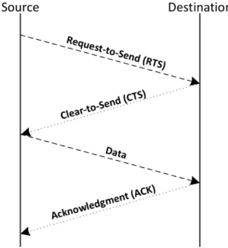
A new class of CSMA-based MAC protocols was proposed in [Che08] for CRNs. These new protocols improve the CSMA in order to operate in CRNs. Both PU’s network and the CRN, are carrier sensed based, with a four-way handshake (Figure 2.2).
Source Destination
The basic operational mode for the system is described in [Che08] and has the following order:
• After sensing the carrier for a specific τp time before the transmission, the PU will
send a request-to-send (RTS) (if the channel was sensed as idle) to the base station of the PU network, in order to begin the packet transmission.
• If a corresponding clear-to-send (CTS) is received successfully, then the data packets will be transmitted, followed by an acknowledgment (ACK).
In case of failure in the CTS reception, the data packets will be sent when the channel becomes idle again after a new sense.
• If a CR or any other PU device starts a transmission, the channel will be sensed as busy.
The operating mechanism of these protocols can be defined in four steps:
1. When a new packet is waiting for transmission and the channel is observed busy, a CR starts to sense the channel for a time duration τs after the busy period. At
the end of this sensing time, it will send a RTS to the CRN base station to gain priority over the channel, even if the channel is sensed as busy (a PU is transmitting a packet).
2. If the RTS is received by the CR device with no collision detected, then the CR receiver will calculate the best transmitting power and rate. If the rate and trans-mission power could be calculated, then the CR receiver will send them back to the CR transmitter through the CTS, otherwise no CTS will be sent.
3. If the CTS is received by the CR transmitter, then it starts transmitting the data packet with the calculated data rate and transmission power that were received in the CTS and previously calculated by the CR receiver. In case of a missed CTS reception, the CR transmitter waits until the end of the next carrier sensing period to send another RTS.
2.6. CSMA AND MAC IN COGNITIVE RADIO 15
These protocols use adaptive power and rate communication scheme between the CR devices. This is essential in order to achieve the best rate and transmission power when a PU is present and to allow simultaneous transmissions from the CR devices. The main goal of the protocol is to achieve the best rate and transmission power for the CR devices without increasing the interference level in a way that could cause failures in the PUs current transmissions. To make this possible, it is essential to guarantee an acceptable interference level of the PUs. This level is used to calculate the best rate and transmission power for every CR device as it is described in [Che08].
2.6.1.3 Achievements
As mentioned in [Che08], this protocol, allows the coexistence between the PUs network and the CRN and also provides simultaneous packet transmission for the CR devices during any PU transmission, increasing significantly the average throughput of the CRN.
2.6.2 Two-level MAC Protocols for Cognitive Ratio Networks
Other MAC protocols, as the one presented in [Won11], were designed to solve the problem that arises when CRNs try to access the medium that is occupied by PUs, are the slotted CR-ALOHA and the CR-CSMA.
These protocols use a two-level opportunistic spectrum access (OSA) strategy. The pri-mary objective for this strategy is scheduling the SUs’ packets transmissions in an effi-ciently manner and simultaneously protect the PUs transmissions.
2.6.2.1 Slotted CR-ALOHA and CR-CSMA Spectrum Access
The random access model for these protocols is based on CSMA for CRNs where no control channel is used and SUs share the same channel with PUs.
As referred in Subsection 2.6.2, these protocols were implemented using a two-level OSA strategy and both protocols have the first level in common.
probability based on a specific threshold value. The amount of bits sent can be easily adjusted by changing the sensing time of the SUs. The SUs can also use the detection and false alarm probabilities to choose when to transmit packets.
• Second level for CR-CSMA and slotted CR-ALOHA - On this level, similar operations to the standard MAC protocols take place. This level handles the SUs packet transmissions. The operation scheme implemented in this level is different for both protocols, and this feature distinguishes them from each other, despite using the same MAC frame structure.
... Spectrum
Sensing TP1 ... TPj ... TPM
Spectrum Sensing TP1
Time Axis
Frame i
T+Tp
Packet Arrival
Tt = M(T+Tp)
Tf = τmax +Tt τmax
Figure 2.3: MAC frame structure for the two-level OSA strategy [Won11].
These two levels combined form the CR-CSMA and slotted CR-ALOHA protocols. The main characteristic of these protocols is the new MAC frame represented in the Figure 2.3 and the framework created to take advantage of this frame structure.
When a PU starts transmitting, the SUs on the network must vacate the channel within
Tdseconds and as result, the spectrum sensing should be executed also withinTdseconds.
This will require discontinuous frame-based channel access for the SUs, which diverges from the traditional continuous access of the conventional networks.
Each frame must have a duration of Tf(Tf 6 Td) seconds. The Tf duration includes a τmax duration for spectrum sensing and a Tt duration for data transmission. The Tt duration includes M transmission periods (Tps) and each one consists in a packet
transmission time ofT seconds and a propagation delay of Tp seconds. Each MAC frame
has duration Tf =τmax+M(T +Tp).
These protocols, mentioned in [Won11], have common features, such as the sensing method and assumptions for the operation scheme.
2.6. CSMA AND MAC IN COGNITIVE RADIO 17
protocols due to its simplicity and easiness of implementation.
SUs implement a positive ACK scheme, which informs the SU if the packet has been transmitted successfully. If the transmission fails, no ACK is received and the packet is retransmitted after the backoff period.
2.6.2.2 Slotted CR-ALOHA Operation Scheme
SS
Packet Generated
PU inactive PU active
SS
1st retransmission 2nd retransmission
Collision R0
T
T SS
Block R1
T SS
Success
x
0
SS– Spectrum Sensing
Figure 2.4: Operation scheme for slotted CR-ALOHA.
The protocol was developed from the standard slotted ALOHA, but with a different dis-crete channel access time and a constrain to protect the primary network was added. For each frame (Figure 2.3), the data transmission will have a duration of l, which is
slotted with a slot size equal to the transmission period (TP) or 1 +α.
Figure 2.4 illustrates the operation scheme for the slotted CR-ALOHA, which can be described by the following rules:
1. If the SU senses the channel as available in the current frame, any packet that arrives in theMth slot of the previous frame will be transmitted in the first slot. This will be applied to the spectrum sensing duration as well. Otherwise, if a packet arrives in the jth slot (j6=M), it will start to transmit at the beginning of the (j+1)th slot.
2. If the channel is sensed as unavailable, any packet arrival within the current frame and up to the (M-1)th slot will wait until the end of the current frame and then will be uniformly retransmitted after the backoff period.
retransmitted after random delays to avoid another collision or to minimize possible repeated collisions.
4. If a packet arrives in the Mth slot of one frame, than it will only be processed in the following frame.
2.6.2.3 CR-CSMA Operation Scheme
SS
Packet Generated
SS
1st retransmission 2nd retransmission
Collision R0
T SS
Block R1
SS Success
x
T Idle Idle 0 PU inactive PU activeSS– Spectrum Sensing
Figure 2.5: Operation scheme for CR-CSMA.
Unlike the slotted ALOHA, in the CR-CSMA it is assumed that the data transmission duration l is divided into mini-slots with length σ, which are denominated as slot-time
(ST). For this protocol, a timing structure similar to the Distributed Coordination Func-tion (DCF) in the 802.11 protocol [IEE07] was adopted and the slot time concept is a part of that legacy.
The CR-CSMA requires that each packet marked for transmission should initiate the transmission procedure in the beginning of the next ST. In order to improve the channel access time, it was assumed that one slot or transmission period (TP) contains m mini-slots (mσ). Due to the short carrier-sensing time being much smaller than the spectrum sensing time, the carrier-sensing time was not taken into account for the operation scheme. The CR-CSMA operation scheme is represented in Figure 2.5 and operates according the following rules:
2.6. CSMA AND MAC IN COGNITIVE RADIO 19
idle, the packet will be transmitted at the beginning of the nextST. In case of being busy, the SU will keep sensing the spectrum until the channel becomes idle again and then will attempt to transmit the packet.
2. In case of detecting the PU as active, if any SUs’ packet arrives within the current frame up to the (M-1)th slot, it will wait until the end of the current frame and then the SU will choose an uniformly distributed backoff time to retransmit the frame.
3. A transmission is considered successful if no collisions occur during the transmission period (BF). If not, the transmission will fail and a retransmission will occur after a random delay to avoid collisions.
4. If any packet arrives during the Mth transmission packet of any frame, it will be marked for retransmission, and will be transmitted in the next frame.
2.6.2.4 Performance Analysis for CR-CSMA and slotted CR-ALOHA
The slotted CR-ALOHA, based in the standard slotted ALOHA suffers a considerable loss in terms of performance when applied to a CR environment, because any PU activity will affect its performance considerably.
The CR-CSMA will have a better performance when compared to the slotted CR-ALOHA. This is due to the fact that SUs are only allowed to transmit from the beginning of a slot in the slotted CR-ALOHA and they do not need to sense the channel. In CR-CSMA, the SUs are much more aggressive in terms of medium access, because they are always sensing the spectrum waiting that the channel becomes idle.
Despite the discrepancy in terms of performance, they have some characteristics in common like the performance/interference factor, the performance/agility factor and the optimal frame length.
reduced. An optimal frame length can be also achieved according the agility/performance ratio.
The performance/interference ratio will depend almost exclusively on the interference re-quirements of protecting the PUs network. Less interference restrictions will be translated in a higher throughput for the SUs network.
2.6.3 SCA-MAC for Wireless Ad-hoc Networks
The SCA-MAC, identified in [Kuo07], is another protocol created to solve the interop-erability issue and achieves a much higher efficiency of spectrum utilization for the CR environment (Section 2.6).
This protocol is a Carrier Sense Multiple Access with Collision Avoidance (CSMA/CA) based cognitive MAC protocol that uses Statistical Channel Allocation (SCA) for wireless ad-hoc networks. It allows CR devices to do real time opportunistic access to any part of the spectrum, independently of being used by PUs or SUs.
This protocol is capable of evolving in terms of knowledge about the radio environment. This knowledge increment by the CR is achieved from several sensing operations and col-lecting the spectrum usage statistics in each one of its operations.
2.6. CSMA AND MAC IN COGNITIVE RADIO 21
2.6.3.1 SCA-MAC Operation Scheme
ACK DATA
CA
DIFS CW CRTS CCTS Control Channel
Data Channels
Figure 2.6: Operation scheme for SCA-MAC.
As is represented in the Figure (2.6), the SCA-MAC protocol relies on three major oper-ations:
1. Environment sensing and learning - A CR device must be able to sense a part of the spectrum in one attempt and gather detailed information about the spectrum usage. One solution to this problem is using the sensing technique referred in Section 2.4, the Cyclostationary technique. Another less advanced method with a lower complexity, is sensing the spectrum several times periodically. This method is adopted by the SCA-MAC protocol.
The sensing period is adjustable and is predefined. When the protocol is executed, a run length of the idle/busy period is kept for each channel. When the idle duration ends due to a transmission from the PU, the run length is recorded in a circular buffer (e.g. a circular buffer of size 300 can record the run length of the last 300 idle periods).
This gathered data will provide the statistics for each channel and the knowledge needed to enable an intelligent channel allocation.
2. CRTS/CCTS exchange over the control channel - Due to the opportunistic channel access, it is necessary to determine which channel should be used by the sender to communicate with the receiver and a mechanism is needed to initiate the communication between them.
The control channel access is managed by a CSMA/CA mechanism which makes the SCA-MAC a decentralized protocol, despite the common control channel.
If a device wants to initiate a transmission, it listens to the control channel and waits until it becomes idle again. Then, it waits a DIFS period for the channel to remain idle before starting the countdown of the contention window (CW). After this count-down, if the channel remains idle, it transmits a Control-Channel-Request-To-Send (CRTS) packet.
When the receiver receives the CRTS, it tries to find the best transmission oppor-tunity based on its own statistics and current channel status. Then, it will reply with a Control-channel-Clear-To-Send (CCTS) packet, which contains the informa-tion related to the best opportunity for transmission. If a collision is detected in the CRTS or CCTS packet, the negotiation process must be repeated with a double CW size.
The CCTS carries the Collision Avoidance (CA) window for the next transmission on the data channel. This backoff window, based in the traditional CW from the CSMA/CA, was implemented in order to reduce the probability of collision of two transmissions occurring simultaneously in the same data channel.
N =|CA|=
2 , n= 0,
2n ,1≤n≤5, 32 , n≥5.
(2.1)
2.6. CSMA AND MAC IN COGNITIVE RADIO 23
3. DATA transmission and ACK over data channels - In case of a successful exchange of the CRTS/CCTS packets, both sender and receiver will use the agreed data channels for the data transmission. The sender starts the countdown of a counter randomly selected from the CA window received in the CCTS and, if the channel is idle in the end of the countdown, it will begin the DATA transmission. The receiver will reply with an ACK after waiting a SIFS period. In case of trans-mission failure the sender has to do all the negotiation process again in the control channel.
2.6.3.2 Statistical Channel Allocation (SCA)
To allocate channels and grant acceptable interference levels simultaneously to the PUs it is imperative to evaluate the successful rate of any transmission in the future. Channel aggregation and the packet length are key variables for the successful rate. The available number of potential combinations with the available channels in the spectrum increases the system complexity, therefore is necessary to lower the complexity in order to allow an efficient channel allocation
The parameters that impact in the channel allocation are enumerated as follows:
1. Optimum operation range - It is very simple to calculate the successful rate for a single channel. Although, this is not true when a successful rate needs to be calculated for several channels.
To reduce the complexity of this operation, a new parameter, r, was introduced in the calculations. It represents the operating range, or the spectrum range which a node must search for transmission opportunities. It translates the level of availability of the existing spectrum ”holes”.
If the spectrum is very crowded, this parameter can be increased, or in other words, the operating range can be increased, allowing the CR device to search for other transmission opportunities in other channels.
the successful rate at the same time.
3. Closest possible opening - Normally, the CR device will choose the first idle channel to transmit, but if an higher successful rate is needed, the device may have to wait for more channels to become idle. In case of occurring several transmission opportunities, the device will choose the one with the shortest waiting time.
The main concern will be the interference levels to the PUs, because they need to be below the successful rate threshold (αT), therefore, the interference level should be under 1−αT.
2.6.3.3 Achievements
The SCA-MAC is able to maintain a success rate at a desired level and also achieving an higher level than the standard MAC in terms of throughput. This is a direct consequence of the spectrum opportunities prediction. Due to its superior performance over the standard MAC protocol, the SCA-MAC is a good choice for CR environments when applied to wireless ad-hoc networks.
2.7
Conclusion
Currently, the radio spectrum is becoming more loaded by the increasing number of mobile devices. The common radio spectrum users, the PUs or licensed users, are unable to use the available spectrum in a totally efficient manner, therefore, a more intelligent spectrum usage is required. The PUs are unable to adapt due to their rigid design, therefore there is a need for network users that are capable of taking advantage of this gaps. These kind of users, SUs, or non-licensed users are capable of overcoming that challenge, largely due to its capacity of sensing the radio spectrum and deciding what spectrum part to use according to the current spectrum occupation and without causing interference with the existing PUs.
There are several MAC protocols proposed for the CR environment adapted from the IEEE 802.11 standard. They grant a more efficient resource usage, performance and also the capability of coexistence between the PUs and the SUs.
2.7. CONCLUSION 25
over the MAC protocol adopted in IEEE 802.11, and they are capable of dealing with the increasing needs of spectrum access.
Chapter 3
Madwifi Description and
Validation
3.1
Introduction
This chapter details the main aspects of the Madwifi (Multiband Atheros Driver for Wire-less Fidelity) project and particularly the LinuxR
Kernel driver for wireless LAN devices equipped with AtherosR
chipsets. It is split in five sections. The second section describes the driver features, main structure, driver version and the computer environment used in the laboratory. The third section explains the driver software organization as well the data structures from the driver data structure and the Kernel modules which constitute the LinuxR
Kernel driver. The fourth section describes the driver’s transmission/reception scheme and all the important features related. The fifth section deals with the proposed module to achieve input and output data validation from the driver. The last section focuses on data analysis and validation from the proposed module.
3.2
Madwifi Description
3.2.1 Early History
Madwifi [Pro12] (Multiband Atheros Driver for Wireless Fidelity) was an open source project started in 2005 which had as primary objective, the development of LinuxR
kernel
drivers for wireless LAN devices with AtherosR
chipsets.
Madwifi original author was Samuel Leffler. He started the project with the purpose of building a meshed community of wireless networks because the existing supported hard-ware was too limited at that time. He contacted AtherosR
to get support for the open source community and he started to work on BSD (Berkeley Software Distribution) sys-tems. His plan was to do the same work on the LinuxR
systems, but every people that he had invited refused and he kept working on Madwifi almost alone. At that time, Greg Chesson, an AtherosR
employee, was the only one who supported Sam Leffler with Mad-wifi, but only on his spare time.
One of his primary goals while developing Madwifi for LinuxR
systems was to implement a 802.11 network layer stack that could be device-independent. As the driver develop-ment took place on LinuxR
systems, the FreeBSD 802.11 stack (net80211) was ported to LinuxR
.
This stack (net80211) was improved for one year on LinuxR
, but the LinuxR
Kernel de-velopers came to believe that net80211 was not the 802.11 stack that they wanted due to design issues, so Sam Leffler felt that he should stop the development due to the lack of support from LinuxR
Kernel developers, and as a direct consequence, Sam Leffler left the project by the beginning of 2005 as well with Greg Chesson who also left AtherosR
and changed his career. At that time, some volunteers decided to keep the development of Madwifi going on and they opened up the development process and also invited many de-velopers to combine efforts in the improvement of one of the most advanced 802.11 drivers available for LinuxR
. Then, the official Madwifi project was born. The project was closed in March of 2012 due to the lack of significant bugs as well of new improvements in the latest version.
During the active time, the project has become an asset for AtherosR
devices and for a large number of LinuxR
users. The most recent LinuxR
driver for wireless LAN devices with AtherosR
chipsets, compatible with 802.11g standard, is designated by ath5k and is based on Madwifi driver, but, the biggest difference between them is that ath5k is not dependent from HAL (Hardware Abstraction Layer) (Subsection 3.3.3) unlike Madwifi, so
3.2. MADWIFI DESCRIPTION 29
3.2.2 Driver Features
The Madwifi driver is considered to be one of the most advanced drivers for WLAN devices for LinuxR
systems. It has several features that allow users to have more control over their wireless devices and also allowing new experiments for academic and professional purposes. It supports several operational modes, like sta (Station), ap (Access Point),
adhoc (Ad-Hoc), ahdemo (Ad-Hoc Demo), monitor (Monitor) and wds (Wireless
Distri-bution System).
The monitor mode is one of the features that makes this driver a very good tool for re-search at this level. It allows “sniffing” raw 802.11 frames from 802.11 frequency spectrum, making possible the analyzing of real-time traffic between several stations or access points. This feature was used in the current work to make possible having a more accurate per-ception of the frames that were transmitted between the stations or access points. This driver allows running several Virtual Access Points (VAPs) on a single wireless net-work card. There is a base device that is usually named “wifi0” and VAPs sit on top of it. It is possible to have one VAP in monitor mode and other in station mode or any other configuration. By default, a single VAP is created in station mode and is called “ath0”. Other VAPs that could be created next, will be named with the same rule (athX), but only the number is incremented by default. This feature allows, for example, “sniffing” 802.11 frames with one VAP while being connected to an access point through another VAP. These VAPs can be managed using a tool called wlanconfig which allows their cre-ation and destruction with several different nodes. This tool comes along with the driver package.
Madwifi also supports the Wireless Extension (WE), a generic API that is distributed with the Wireless Tools package for LinuxR
. This package has a set of tools to manipulate the Wireless Extensions (WE) and the Madwifi driver takes advantage of them enabling on the fly changes and customizations to the driver parameters. Tools likeiwconfig,iwlist,iwspy,
iwpriv and ifrename allow a more detailed control over the driver using the operating
3.2.3 Driver Software License
The Madwifi driver is open source but it depends on HAL (Hardware Abstraction Layer) which is closed source. The driver is provided under three-clause BSD and GPL v2 dual license. The binary HAL is provided under a proprietary license.
3.2.4 Driver Version and LinuxR
Environment
In this work, the chosen LinuxR
operating system is theUbuntu 12.04 LTS 32 Bits with the Kernel version 3.2.0-35-generic-pae. The Madwifi version used is the latest stable release, the v0.9.4 r4180, for 2.6.25 or higher LinuxR
Kernel versions.
3.2.5 Hardware Version and Specifications
The hardware used in this project was the PCI 2.2 network card D-Link DWL-G520
with the AtherosR
AR5212/AR5213 Chipset (rev 01). This chipset uses CSMA/CA
(Carrier sense multiple access with collision avoidance) with ACK (Acknowledgement) for the Medium Access Control (MAC) and can switch between two modulation technologies, Orthogonal Frequency Division Multiplexing (OFDM) or Complementary Code Keying (CCK). These modulations are used according the data bit rate which can reach up to 108 Mbps with Super-G technology.
3.3
Madwifi Software Organization
The Madwifi driver (Appendix A.2) is formed by four main parts. The net80211 stack, the
ath part, HAL and rate algorithms. These parts are the main LinuxR
Kernel modules. The driver has eighteen kernel modules, which are loaded at operating system startup according the user setup and some of them may not be loaded.
3.3.1 Net80211 Stack
As mentioned in Subsection 3.2.1, net80211 was not accepted by LinuxR
Kernel develop-ers, as a default 802.11 network layer stack for future LinuxR
3.3. MADWIFI SOFTWARE ORGANIZATION 31
Net80211 only supports AtherosR
devices, even though, it supported several WLAN de-vices from other hardware manufacturers in BSD systems.
This stack contains generic 802.11 functions and callback functions that can be overridden by devices. It is implemented by several Kernel modules, but the main one, the wlan.o, is always running with another module depending on the operating mode that has been cho-sen. If the network adapter is operating in station mode, it will load thewlan scan sta.o. If the network adapter is operating in access point mode, it will load the wlan scan ap.o. Both kernel modules have specific functions for the selected operating mode.
User Space
System Calls
Ath Rate Algorithms
HAL net80211
Hardware (Atheros® Chipset)
Figure 3.1: Madwifi driver structure.
3.3.2 Ath
In the Madwifi driver, the ath part is responsible for defining AtherosR
3.3.3 HAL (Hardware Abstraction Layer)
As stated at the end of Subsection 3.2.1 and in the beginning of the Subsection (3.2.3), the Madwifi driver depends on HAL (Hardware Abstraction Layer) to operate properly. This software is essential because it establishes the connection between AtherosR
hardware and the driver itself.
The AtherosR
chipsets are able to use a wide range of frequencies and the host software is able to control many radio aspects. To reach an worldwide agreement about transmission power and frequency, many manufacturers like AtherosR
, implemented several solutions to enforce these standards. HAL is one of their solutions for these known security issues, and in this case was the solution adopted by AtherosR
.
HAL is provided in binary form only and any attempt to modify it is very likely to be unsuccessfully. Although, HAL enables a good interaction between the chipset and the driver without compromising the radio transmission rules.
HAL is split in two parts, the precompiled binary part and the open source software part that is constituted by three files, ah os.c, ah os.h, and ah osdep.h. These files compiled with the binary file will produce the loadable Kernel module ath hal.o.
Any modification required due to changes in the LinuxR
operating system can be achieved by editing the ah os.c file and mapping HAL and kernel functions calls to one another.
3.3.4 Rate Algorithms
Madwifi comes with three different bit rate control algorithms. Onoe, amrr and sam-ple. A fourth one, Minstrel was imported to Madwifi from LinuxR
mac80211 stack by
Felix Fietkau on January 2005 which was originally designed and implemented by Derek Smithies. This algorithm bases its rate choices on the packets transmission success rates.
Onoealgorithm chooses bit rates by measuring the number of retries per packet. If packets need to be retransmitted at least once, it decreases the bit rate and only will increase it when at most 10% of packets do not need to be retransmitted.
Ammr uses another method to define the bit rate. It uses exponential backoff to avoid increasing the bit rate.
![Figure 2.3: MAC frame structure for the two-level OSA strategy [Won11].](https://thumb-eu.123doks.com/thumbv2/123dok_br/16573549.738114/42.892.184.730.438.566/figure-mac-frame-structure-level-osa-strategy-won.webp)