Júri:
Presidente: Doutor Luís Manuel Camarinha de Matos
Arguentes: Doutor Ricardo Jorge Silvério de Magalhães Machado Doutor Arnaldo Silva Rodrigues Oliveira
Vogais: Doutor Luís Filipe dos Santos Gomes Doutor Carlos Baptista Cardeira
Doutora Anikó Katalin Horváth da Costa
Fernando Joaquim Ganhão Pereira
Dissertação para obtenção do Grau de Doutor em Engenharia Eletrotécnica e de Computadores
Licenciado em Engenharia Eletrotécnica e de Computadores
The DS-Pnet modeling formalism
for cyber-physical system development
Orientador: Doutor Luís Filipe dos Santos Gomes Prof. Associado com Agregação
The DS-Pnet modeling formalism for cyber-physical system development
Copyright © Fernando Joaquim Ganhão Pereira, Faculdade de Ciências e Tecnologia, Universidade Nova de Lisboa.
ACKNOWLEDGEMENTS
I want to express my gratitude to Prof. Luís Gomes, my supervisor, for his support, guidance, knowledge, and friendship.
I would like to thank the Thesis Accompanying Committee (CAT), composed of Prof. Ricardo Machado, Prof. Anikó Costa, and my supervisor, for their recommendations.
I would also like to thank "Universidade Nova de Lisboa" (UNL) and "UNINOVA – Institute for the Development of New Technologies", Portugal, in particular to Prof. Adolfo Steiger Garção, Prof. Luis Camarinha-Matos, and Prof. João Goes.
I want to thank my team members, colleagues, and friends, for their contribution and friendship from the GRES research group:Filipe Moutinho, Rogério Campos Rebelo, Anikó Costa, João Paulo Barros, José Ribeiro, José Rocha, José Pedro Lucas, Rui Pais.
I would like to thank my work colleagues, and friends, from INOCAM, CEI/ZIPOR and ISEL for their support, releasing me from many work tasks in order to provide time to proceed with the PhD work. I would like to thank Rui Guerreiro that contributed with sugestions and helped proof read the text.
I would like to thank all my friends for their encouragement and friendship during this time.
Finally, I thank my family for their love!
This work was partially supported by project:
Petri-Rig - A Petri net based framework for embedded systems engineeRInG (Petri-Rig - Ambiente de desenvolvimento de sistemas embutidos baseado em redes de Petri ); Maio 2013 – Outubro 2015; Consórcio: UNINOVA, Inst. Politécnico de Beja; FCT sponsored; Funding: 109.663€; Ref.: PTDC/EEI-AUT/2641/2012
Resumo
Este trabalho apresenta o formalismo de modelação DS-Pnet (Dataflow, Sinais e redes de Petri), criado para o desenvolvimento de sistemas ciber-físicos, combinando as características das redes de Petri e dataflows para possibilitar a modelação de sistemas mistos, contendo partes reativas e operações de processamento de dados. Herdando as potencialidades da classe de redes de Petri progenitora IOPT, incluindo a interface externa composta por sinais e eventos de entrada e saída, a adição de operações de fluxo de dados (dataflow) contribuiu para melhorar a capacidade de modelação para especificar a transformação matemática de dados e expressar graficamente as dependências entre sinais. Sistemas centrados em dados, que não requerem controladores reativos podem ser modelados usando apenas dataflows.
A composição de modelos baseada em componentes permite reutilizar componentes previamente desenvolvidos, criar bibliotecas de componentes e decompor hierarquicamente modelos em diversos sub-sistemas.
Foi definida uma semântica de execução precisa, tendo em conta a relação entre nós de dataflow e rede de Petri, que oferece uma abstração para definir a interface entre controladores reativos e sinais de entrada e saída, incluindo sensores e atuadores analógicos.
O novo formalismo é suportado por um conjunto de ferramentas com interface Web, IOPT-Flow, que oferece ferramentas para criar e editar modelos, simular a execução de modelos diretamente no navegador Web, para além de ferramentas de validação de modelos e geração automática de código (C, VHDL e JavaScript) que produzem hardware e software para correr em dispositivos computacionais embutidos.
Foi criado um novo protocolo de comunicação para automatizar a implementação de sistemas ciber-físicos distribuídos compostos por redes de componentes remotos que comunicam usando a Internet. A ferramenta de edição pode ser ligada diretamente a dispositivos embutidos remotos que executam modelos DS-Pnet, permitindo importar componentes remotos para novos modelos, contribuindo para simplificar a criação de aplicações distribuídas onde a comunicação entre componentes localizados em nós diferentes é especificada pelo desenho de arcos.
São apresentadas várias aplicações que foram elaboradas para validar o formalismo proposto e as ferramentas associadas, incluindo soluções implementadas em hardware, aplicações industriais e aplicações de software distribuídas.
Abstract
This work presents the DS-Pnet modeling formalism (Dataflow, Signals and Petri nets), designed for the development of cyber-physical systems, combining the characteristics of Petri nets and dataflows to support the modeling of mixed systems containing both reactive parts and data processing operations. Inheriting the features of the parent IOPT Petri net class, including an external interface composed of input and output signals and events, the addition of dataflow operations brings enhanced modeling capabilities to specify mathematical data transformations and graphically express the dependencies between signals. Data-centric systems, that do not require reactive controllers, are designed using pure dataflow models.
Component based model composition enables reusing existing components, create libraries of previously tested components and hierarchically decompose complex systems into smaller sub-systems.
A precise execution semantics was defined, considering the relationship between dataflow and Petri net nodes, providing an abstraction to define the interface between reactive controllers and input and output signals, including analog sensors and actuators. The new formalism is supported by the IOPT-Flow Web based tool framework, offering tools to design and edit models, simulate model execution on the Web browser, plus model-checking and software/hardware automatic code generation tools to implement controllers running on embedded devices (C,VHDL and JavaScript).
A new communication protocol was created to permit the automatic implementation of distributed cyber-physical systems composed of networks of remote components communicating over the Internet. The editor tool connects directly to remote embedded devices running DS-Pnet models and may import remote components into new models, contributing to simplify the creation of distributed cyber-physical applications, where the communication between distributed components is specified just by drawing arcs. Several application examples were designed to validate the proposed formalism and the associated framework, ranging from hardware solutions, industrial applications to distributed software applications.
Table of Contents
1 Introduction...1
1.1 Background and motivation...1
1.2 Preliminary contributions...5
1.3 Research questions...7
1.4 Research method...9
1.5 Overview of the IOPT-Flow framework...9
1.6 Contributions and publications...18
1.7 Document structure...20
2 Literature Review...21
2.1 Petri nets...21
2.2 Model checking...22
2.3 Execution semantics and non-autonomous properties...23
2.4 Low level and high level net classes...25
2.5 High level net execution strategies...26
2.6 Model composition and hierarchical structuring...27
2.7 Model composition based in signal and event communication...28
2.8 The IEC61499 standard...30
2.9 Automatic code generation...31
2.10 UML statecharts and activity diagrams...32
2.11 Model file formats...33
2.12 Reactive systems and synchronous dataflows...34
2.13 Matlab/Simulink...35
2.14 Cyber-physical systems...36
3 The DS-PNET Modeling Formalism...39
3.1 Language core...39
3.2 Dataflow operations...43
3.3 Components...46
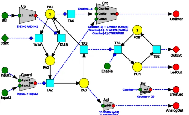
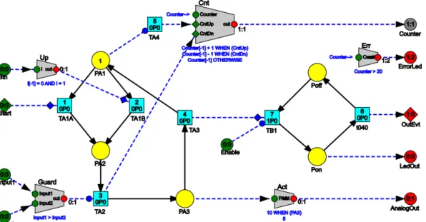
3.4 Example DS-Pnet model...49
3.5 Model files...52
3.6 Execution Semantics...54
3.6.1 Formal definition...54
3.6.2 Execution semantic rules...57
4 Automatic Code Generation...63
4.1 JavaScript generated code...67
4.2 VHDL Generated code...68
4.3 C Generated code...70
4.4 Interface board for industrial applications...74
4.5 External/Foreign Components...76
5 Distributed DS-Pnet Models...79
5.1 Shared distributed components...87
5.2 JSON/HTTP Communication Protocol...91
5.2.1 User authentication and privilege levels...95
5.2.2 Request types...96
5.2.3 Server...100
5.2.4 Client...101
6.3 Remote Debugger...117
6.4 Node-Split...119
6.5 Automatic code generation...120
6.6 Import and export IOPT models...121
6.7 IOPT Model Checking...122
6.8 Component Library...125
6.9 Standard foreign component library...128
6.9.1 Arrays...129
6.9.2 Data file input and output...130
6.9.3 System time information...131
6.9.4 Random number generator...132
6.9.5 Graphical user interface...133
6.9.6 Audio samples...135
6.9.7 Industrial ModBUS Gateway...136
6.10 Debug And Model-Checking...138
6.10.1 Application example...141
7 Validation Applications...147
7.1 Bushless servo motor controller...148
7.1.1 Model development...149
7.1.2 Prototype implementation:...155
7.1.3 Results...155
7.2 Distributed multi-user game with graphical interface...158
7.2.1 Results...162
7.3 Graphical console for an industrial variable speed drive...165
7.3.1 Results...169
7.4 Distributed cyber-physical system simple application...171
7.4.1 Results...173
8 Conclusions and future work...175
8.1 Research question 1...175
8.2 Research question 2...178
8.3 Research question 3...180
8.4 Results and comparison with other technologies...181
8.4.1 Traditional programming languages (C/C++, Java, Python, VHDL, etc.):.182 8.4.2 IOPT-Tools...184
8.4.3 Industrial automation development languages...185
8.4.4 Labview and Matlab/Simulink...186
8.5 Future work...187
Index of figures
Fig. 1: Ladder diagram "emulation" model...10
Fig. 2: Petri net example. Places drawn as yellow circles, transitions as blue bars and arcs as arrows...22
Fig. 3: Incidence matrix...23
Fig. 4: High level Petri net example...25
Fig. 5: Component...47
Fig. 6: Example DS-Pnet model...49
Fig. 7: Anchor equivalence: the operation on the left is equivalent to the dataflow node on the right...55
Fig. 8: Micro-step and nano-step sequence numbers...60
Fig. 9: Automatic code generation information flow (steps 1-5)...64
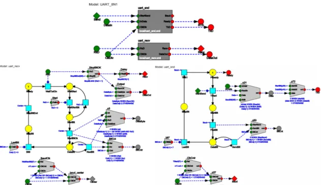
Fig. 10: A UART model (top) with the receiver(left) and sender (right) component implementation models...70
Fig. 11: Isolated digital I/O board w/ SPI interface (2 boards)...75
Fig. 12: (Not)Synchronous Channel on a distribted model...80
Fig. 13: One publisher and multiple subscribers...82
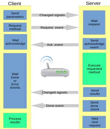
Fig. 14: Client/server event driven comunication...83
Fig. 15: Client-server communication...84
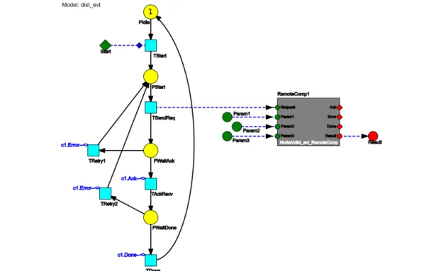
Fig. 16: Example: Event based communication with remote component...85
Fig. 17: Same example with the handshake controller Petri net encapsulated in a local component (on the right)...86
Fig. 18: Proposed infrastructure for concurrent client access...89
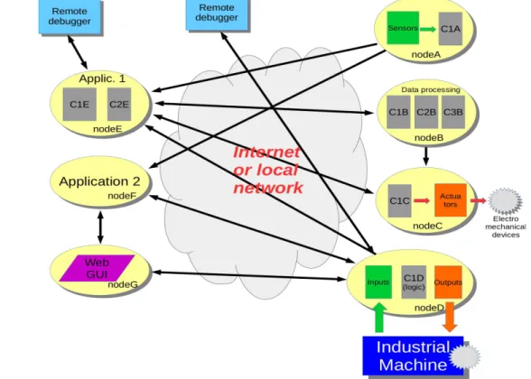
Fig. 19: Possible CPS network topology example...91
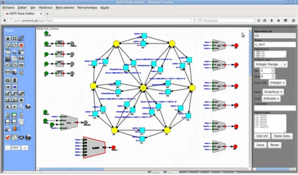
Fig. 20: The IOPT-Flow Editor...106
Fig. 21: Editor interaction/feedback loop...108
Fig. 22: The Expression Editor...110
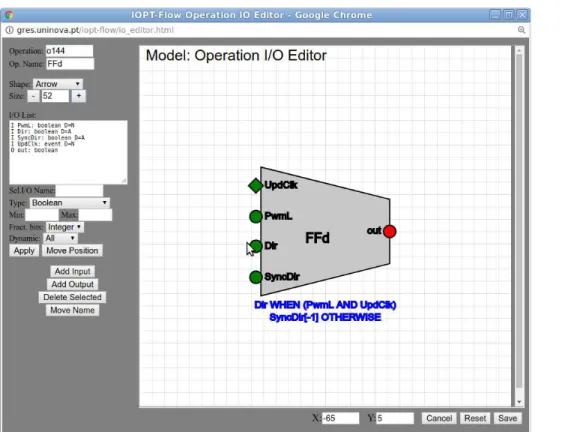
Fig. 23: The operation input/output editor...111
Fig. 24: Clipboard View...112
Fig. 25: View component implementation model...112
Fig. 26: Import DS-Pnet components from remote embedded nodes...113
Fig. 27: The IOPT-Flow simulator (Chrome Web browser)...114
Fig. 28: Waveform view window (simulation history)...115
Fig. 29 The IOPT-Flow remote debugger application (Chrome browser)...117
Fig. 30: Code generation options...120
Fig. 31: IOPT Petri net view...122
Fig. 32: State space generation progress window...123
Fig. 33: The query editor (IOPT model checking)...123
Fig. 34: A state-space graph of an IOPT model extracted from a DS-Pnet...124
Fig. 35: IOPT-Flow Editor tool - Library dialog (user interface widgets folder)...125
Fig. 36: Ladder-logic library components specified as dataflow operations...126
Fig. 37: The t_ON timer and Up/Down counter native components. Component interfaces (left) and implementation models (right)...128
Fig. 38: Foreign array components: vector and matrix...129
Fig. 39: The file input / output foreign components...130
Fig. 40: Using time-stamps to synchronize the position of 3 motors...132
Fig. 42: Graphical user interface components...134
Fig. 43: User interface test application...135
Fig. 44: ModBUS component test model...136
Fig. 45: ModBUS + UI motor control application running on a Raspberry-PI 2 card, with an LCD+touchscreen hat and an USB-RS485 serial converter...137
Fig. 46: Concrete mixer plant...141
Fig. 47: Cement mixer controller model...142
Fig. 48: Cement mixer main model: controller + plant...144
Fig. 49: Cement mixer plant model...144
Fig. 50: Closed-loop servo motor controller top-model...148
Fig. 51: Quadrature encoder model...149
Fig. 52: Digital PID Controller model...150
Fig. 53: The diff_in(left), diff_out(center) and nfilter(right) models...151
Fig. 54: The PWM generator model (left) and the cntr_up_dn component model (right) ...152
Fig. 55: The BLDC Commutation table model...153
Fig. 56: The Speed/Position selector model...154
Fig. 57: Prototype diagram on the left and photo on right: BLDC Motor, FPGA and Inverter boards...154
Fig. 58: Distributed dual-user «pong» game (graphical user interface)...158
Fig. 59: The entire single-user game model fits in a single editor page...159
Fig. 60: The main game model: game engine + player1 interface...160
Fig. 61: The player2 model...160
Fig. 62: The game engine component model...161
Fig. 63: Game user interface...162
Fig. 64: Variable speed drive console application (running on a laptop PC)...165
Fig. 65: Console main model...166
Fig. 66: ModBUS Scan-cycle model...167
Fig. 67: The console user interface component...169
Fig. 68: Example of a distributed DS-Pnet application model...171
Fig. 69: Implementation models of the IOX8 (left) and Kit (right) components...172
Index of Tables
Table 1: Petri net elements...40
Table 2: Dataflow nodes...41
Table 3: Transition firing inhibition constructs...42
Table 4: Expression operators...44
Table 5: C code generator output files...72
Table 6: Privilege levels...95
Table 7: Communication protocol request/procedure list...98
Table 8: Editor toolbox functions...109
1
Introduction
1.1 Background and motivation
The emergence of low cost computing platforms lead to the vast proliferation of embedded systems with increasing levels of sophistication, automating many tasks that were previously performed by human operators, with applications in the domains of industrial systems, home appliances, medical devices, automatic vending machines, security and surveillance applications, in-vehicle systems and entertainment applications, among others. The fast dissemination of the Internet and the wide availability of inexpensive networking technology brought Internet connectivity to the recent generations of embedded devices, contributing to the birth of the Internet of Things.
Applications running on mobile computing devices may be employed for the remote monitoring and operation of solutions employing distributed networks of remote devices, often taking advantage of public data provided by existing infrastructure, as smart grids and city traffic control systems. These capabilities enable the development of even more sophisticated systems, including access to automatic payment systems and connection to social media platforms.
Over the past decades, model based formalisms have been successfully used to the development of embedded system controllers, helping to cope with the increasing levels of complexity involved. With this approach, instead of directly writing software code or hardware descriptions, developers start with the design of high level models that specify the desired system behavior and data structures employed, frequently based on graphical formalisms as Petri nets [29][30][31][32][33], UML activity diagrams and statecharts [34][35][36].
With thousands of academic publications, Petri nets have been the focus of many research groups leading to the advent of a growing number of Petri net classes adapted to different fields. However, most of these classes only support autonomous systems and are only used for simulation and model-checking purposes [37][38]. In contrast, non-autonomous classes, as IOPT nets [29] and NCES [39], use inputs and outputs to communicate with the external world, going beyond the realm of simulation to allow the implementation of real controllers running on physical hardware [8][14].
Non autonomous Petri nets offer a feature set very well adapted to the design of embedded system controllers. System state can be mapped to places and the behavioral rules that define system evolution are specified using transitions. Petri nets inherently handle the concepts of parallelism, concurrency and synchronization, frequently used in embedded system controller design. The design of systems containing multiple sub-systems that compete for shared resources usually starts with the definition of independent state machines for each sub-system, without concurrency concerns. Next, the critical sections that require exclusive access to the shared resources are synchronized with additional places that work as semaphores. This method avoids possible state explosion problems that would occur trying to design entire systems using a single state machine.
To perform their job, controllers must communicate with the controlled systems and the external world, involving the transmission of different types of information, including sensor gauged data, drive mechanical actuators and communicate with users. As a result, the external interface of the non autonomous models must cover a wide range of data types to support both digital and analog signals and events. The controller models react to these events and changes in input signals, producing the consequent output responses. However, the values read from the input sensors usually require some sort of signal processing and conditioning before being ready for decision making. For example, input signals may require units conversion, noise filtering and threshold cross checking. In the same way, output values are generally calculated with basis on the system state and input values.
expressions, frequently hidden from the main view to avoid screen clutter, contributing to reduce model readability.
High level Petri nets offer an interesting data processing solution, storing data inside tokens, that may be manipulated upon transition firing. Unfortunately this solution has several drawbacks. First, when a model employs interdependent calculations it imposes propagation delays, as new calculated values will only be available on the next execution step. Second, as a single place may store multiple tokens, it conducts to iterative execution semantic algorithms that increase the complexity of hardware implementation and do not guarantee a fixed step-execution time.
From another side, the functionality of the embedded systems has been constantly improving, leading to more complex controller models, raising the need for structuring mechanisms that enable the sub-division of complex controllers into several components. Using this strategy, a controller can be composed from an hierarchy of sub-systems and the behavior of each sub-system can be specified using simpler models. Component models may be individually tested and model-checked, with benefits in terms of development time. Finally, the components can be instantiated multiple times in the same project, or reused on future projects, taking advantage of the design and model-checking effort previously carried, allowing the creation of libraries containing frequently used components.
Almost all modeling formalisms, programming languages and hardware description languages include structuring mechanisms to enable the top-down decomposition of complex systems into simpler components [36][43][44], or the bottom-up composition of new applications from existing components. In all cases, the mechanisms used to pass information between components and encapsulate local data inside each component play a crucial role.
problem has already been presented by other authors [39][46] discussing the NCES Petri net class.
Modern embedded systems, built on top of networks combining computational sub-systems and physical devices, enter in the field of Cyber-Physical Systems (CPS) [47][48], dealing not only with classic control problems and the idiosyncrasies of communication networks and computational systems, but specifically with the problems that arise at the intersection between physical and computational sub-systems. Applications of CPS frequently listed in the literature, include distributed industrial systems, smart electrical grids, in-vehicle systems and traffic control systems, bio-medical and health-care systems, smart sensor networks and industrial robot systems, using the same network infrastructure that is usually employed in the Internet of Things (IoT) [49].
Involving both mechanical sub-systems and computational devices, Cyber-Physical Systems are viewed as an interdisciplinary field, requiring the collaborative work from different engineering disciplines, including mechanics, computer science, computer engineering, systems engineering and electronics. These disciplines approach problems from different perspectives, use different terminologies and employ different tools, raising the need for new development formalisms that may appeal to designers coming from different backgrounds. Again, model based development formalisms may be used as a common ground: high level graphical models may be used to create information systems and specify system behavior in a way that is easily understood by all people involved, hiding the low level details required by the traditional programming languages used in embedded-system design.
1.2 Preliminary contributions
The problems addressed in this work were identified along several years of research and development in related fields. This work resulted in several contributions
to the IOPT tools framework, available on-line at «http://gres.uninova.pt/IOPT-Tools/»,
whose results were disseminated over 24 publications, including conference and journal papers, two book chapters and a user manual.
Contributions to a first-generation of IOPT support tools, include an automatic generator of debug screens for the Animator tool [3] and a DDR memory interface to support Animator graphical user interfaces on FPGA platforms [2][4].
Contributions to the IOPT Petri net class have been added to the current IOPT meta-model [5][17] descriptions, include new syntax rules for mathematical expressions, the addition of output actions associated with transition firing and definition of arrays:
a) Changes in mathematical expressions include the support for new operators and the definition of a new hierarchical syntax, to support multiple automatic code generators in a language independent way.
b) Transition actions allow the definition of output signal values using arithmetic expressions. transition output signals memorize the last affected value and are a part of the system state vector, along with place marking and signals associated with output events. In order to simplify state-space computation, the expressions used to calculate transition output signals can only contain literal values and other system-state variables.
c) Arrays are used for two purposes: First, constant arrays enable the definition of general purpose functions with one or two integer arguments, storing a table of pre-calculated function values, that can be used by both the software code generators and the hardware description code generators. Second, variable arrays, whose contents can change during model execution, enable the application of the IOPT formalism to problems that deal with large amounts of data. In order to support hardware implementations, arrays indexes are always performed using a single range variable. As a consequence, simultaneous concurrent access to different array positions must be explicitly dealt by the model designer.
subsystem [9][15], a simulator [19] and a debugger based on a remote debug and monitoring communication protocol [18][22].
Four application papers, describing FPGA based prototypes in the field of industrial electronics, consisting of a controller for a high-voltage Marx pulse generator [1][10][11] and a brush-less DC motor controller [12], played an important role in the identification of the research questions and underlying problems described in this text:
a) The controllers implemented in both prototypes presented a relatively high level of complexity and a modular approach was employed in each case. The final systems were built using the composition of smaller components, communicating with each other and the external world using input and output signals. In both cases, the component instantiation and signal connections was performed by manually writing VHDL code.
b) In both prototypes, several modules were first designed in paper using a dataflow approach and were manually translated to the chosen development language: direct VHDL in the first case and IOPT models in the second. These dataflows were even employed in the resulting papers as a simplified graphical description of some of the components (PWM generator, etc.) and as a diagram to depict the entire systems.
The work presented in this document is focused around the DS-Pnet (Dataflows, Signals and Petri nets) modeling formalism and the associated IOPT-Flow tool framework [26][27]. DS-Pnets combine the characteristics of the IOPT Petri net class with dataflows and model composition based on components. Dataflow nodes are used to specify mathematical operations and the dependencies between signals in a graphical way, replacing the expressions that were previously inserted into place and transition annotations.
Finally, it is important to recall that the contributions described in this section were based on previous work that started on the Uninova/CTS GRES research group, with the definition of the IOPT class [29][54] and the creation of the first-generation support tools, including a version of the Snoopy Petri net editor [55] with support for the IOPT class, an automatic C code generation tool [56][57], a VHDL code generation tool [58], an Animator tool [59] for interactive user interface design, with support for VHDL hardware implementations [60] and a Split tool [61] to support distributed execution [62].
1.3 Research questions
Based on the problems identified during the preliminary work phase, the following research questions were formulated:
Research question 1
Which modeling formalisms can be used in association with Petri nets to support the design of cyber-physical systems, including both the control logic and data operations ?
Hypothesis
a) Cyber-physical systems and embedded systems can be designed through the composition of multiple components, or function blocks, connected through input and output signals and events. The individual function blocks can be designed using IOPT nets, a low-level Petri net class designed for embedded system controller development.
b) The addition of a complementary modeling formalism to define data structures and mathematical operations, used in synergy with the Petri nets, enables the definition of complete embedded systems, including the control logic (Petri nets) and data. An higher level synchronous dataflow, describing a network of mathematical operations applied to input signals, output signals, internal signals and system state variables, can be used to define the data part of the embedded systems.
Research question 2
Hypothesis
a) By composing the entire systems into a flat model containing all function blocks, it is possible to identify global loops inside the synchronous dataflow Petri net nodes, that would prevent deterministic execution.
b) A set of syntactic and semantic rules to regulate the bidirectional interaction between the Petri net nodes and dataflow components must be defined.
c) The loops identified in a) can be broken by inserting registered internal signals. These registered internal signals may be used to define part of the dataflow system state vector.
d) Syntactic and Semantic rules must be applied to the external interface of function blocks to enable execution correctness in distributed environments.
e) Analyze the advantages of possible automatic code generation strategies based on individual components or on flat models of the entire system, according to the target architecture (software or hardware).
Research question 3
How to model check the systems described in R.Q. 2 ?
Hypothesis
a) The construction of the state-space graph of the individual function blocks and the complete systems, enables model checking and property verification. The definition of the execution semantics and the identification of all system state variables is enough to allow state-space computation.
1.4 Research method
In order to answer the previous research questions and verify the hypothesis, the following steps were executed:
1 – During a preliminary phase, contributing to the IOPT tools framework, knowledge about the state of the art was acquired, permitting the identification of gaps and unsolved problems
2 – Formulate research questions based on the identified problems
3 – Elaborate a set of hypothesis to answer the research questions
4 – According to the formulated hypothesis, create a new development formalism and study the respective execution semantic rules
5 – Create a set of support tools to enable the application the new formalism to the design of cyber-physical systems
6 - Define criteria to compare validation application results with other development technologies
6 – Using the tools created in 5, design a set of validation applications
8 – Analyze results and validate the hypothesis
1.5 Overview of the IOPT-Flow framework
This section presents an overview of the DS-Pnet modeling formalism and the associated IOPT-Flow tool framework, addressesing the goals that lead to the creation of the new tools and potential areas of application.
of the parent IOPT Petri net class may be mapped into DS-Pnets and an automatic translation tool has been created.
Composed of signals and events, the external interface of a DS-Pnet model may be used to read sensors, manipulate actuators or communicate with other DS-Pnet models, under the form of components, that may be placed locally or distributed on remote locations, enabling the creation of CPS applications over networks of distributed components.
In order to appeal to a wider base of users coming from different engineering backgrounds, the text inscriptions that traditionally have been used by other Petri net dialects to specify processing instructions, were replaced by graphical dataflows. Dataflow languages have been used in varied areas of engineering, and popular prototyping software packages as Matlab and Simulink [63] offer dataflow functionality. Regarding industrial automation, the most popular graphical languages used on programmable logic controllers, Ladder diagram [64] and Grafcet [65], can be emulated respectively using dataflows and Petri nets. Developers coming from an industrial automation background may use a library «Ladder» folder containing dataflow operations implementing traditional Ladder constructs. Figure 1 presents a DS-Pnet model using dataflow operations to emulate Ladder contacts and a «T-On» timer component frequently used in Ladder diagrams.
Dataflow graphs offer several advantages, presenting a graphical representation of the dependencies between input, output and intermediate signals that contribute to improve model readability. Like functional programming languages, it restricts the number of signal value assignments to a single expression, contributing to reduce modeling mistakes. By employing a synchronous execution paradigm, assuming that all
mathematical operations are executed instantaneously, it allows signal propagation though multiple internal computational nodes in a single execution step.
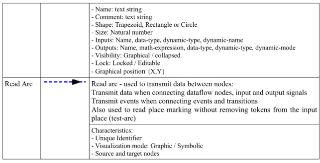
The dataflow part of DS-Pnet model is composed of arcs and operations. Data flow nodes, called operations, are used to perform data processing by applying mathematical transformations to input data and producing one or more results. Arcs are used to connect signals between different nodes, including input and output signals and events, Petri net place and transition nodes, dataflow operations and components.
In order to simplify the creation of complex models, DS-Pnets support model composition based on components. Any DS-Pnet model may be used as a component to create higher level applications. In the same way as DS-Pnet models, the external interface of components is composed of input and output signals and events. Components may be used as building blocks to compose high level applications, chosen from libraries of existing components, or used for the top-down decomposition of complex systems into simpler sub-systems. As each component may contain internal data, under the form of internal signals and Petri net state variables, and processing instructions implemented using transitions and dataflow operations, components can be viewed as objects where method execution is triggered by input events, or as actors communicating with each other using input and output signals [66].
A DS-Pnet component may be native or foreign. Native components are designed using DS-Pnet models. Foreign components are used to encapsulate external sub-systems designed using other modeling formalisms and development languages. Foreign components are created using empty DS-P models, containing just the input and output signals and events that define the component interface, and selecting the «foreing» target implementation property. When the automatic code generation tools find this property, they will create a set of data structures and stub functions where the developer may insert code to initialize and execute the components.
On hardware projects, foreign components permit using existing integrated circuits and IP modules defined using hardware description languages into DS-Pnet applications. On software projects, foreign components permit using external code software inside DS-Pnet applications, including existing algorithms developed using standard programming languages, access any resources provided by computer operating systems, and communicate with legacy embedded platforms.
operation. This way, the model edition tools can connect directly to the controllers running on the embedded computing devices to request the list of available components and download the respective DS-Pnet models. Remote components may be inserted into the new application models and used in the same way as local components. The connection between local and remote components is performed using dataflow arcs. This way, the operation of reading remote sensors or driving remote actuators is as simple as drawing arcs (after importing components from remote servers to the new application model), and all communication details are dealt by the automatic C code generation tool.
Remote components can be used to create an abstraction for physical devices, including sensors, actuators, motors and entire mechanical systems, greatly simplifying the creation of CPS applications. Remote foreign components may be also used to interface with legacy industrial devices, including programmable logic controllers, variable speed drives and numeric controlled machinery. To assist the integration of DS-Pnet applications in industrial environments, a foreign component implementing a gateway for the ModBUS [67] industrial field-bus was developed, enabling the communication and control of almost all industrial automation devices present on the market.
In order to ensure deterministic operation, the execution semantics of DS-Pnet models was analyzed, studying the bi-directional relationship between dataflow Petri net nodes. Dataflow operations may read the system state under the form of place marking and events triggered by transition firing. The evolution of the Petri net part of the models is conditioned by transition guards, transition input events and synchronous channels between transitions, defined using dataflow arcs that end at the respective transitions. A set of executions rules was defined, used as a basis for the automatic code generation tools.
The execution semantics of distributed execution of Cyber-Physical Systems composed be networks of remote components presents a different level of problems. In addition to the usual concurrency problems presented by parallel execution architectures and differences in performance between nodes running on heterogeneous hardware platforms, the choice of the Internet as a communication medium brings new concerns, including variable network latency delays, unpredictable network bandwidth and possible data loss.
modules is performed using signals and events. However, the IEC61499 function blocks usually communicate over local networks using industry standard field-buses and offer two types of function blocks for Internet communication: publishers/subscribers and master/slave [70]. In contrast, the proposed DS-Pnet communication protocol is based on HTTP and does not enforce any usage patterns, employing the same approach for both local nets and long distance Internet connections.
Four forms of remote component users were typified, the observer, the client, the master and the administrator, with details presented in the corresponding chapter. Observers just subscribe changes from remote component output signals, for example to monitor sensors or the internal state of remote sub-systems. Multiple observers may subscribe the same values without conflicts. In contrast, all other usage types may suffer from conflicts and synchronization problems.
Events play a critical role to manage synchronization and concurrency problems. In a typical use case, when an application wants to invoke a certain methods on a remote component, it first passes parameter data through input signals and then sends an event that will trigger an action on the remote side. The remote component might answer immediately with another event to acknowledge the request reception, or might just place an answer on output signals and trigger a completion event.
The responsibility to avoid synchronization errors and ensure the correct behavior lies on both developers, the component designer and application designer. As long as the parameter signals hold the correct values when the events are triggered, the communication middle-ware ensures that these values do not arrive out of order. In case of network problems and communication fails, both the component and applications are informed by setting predefined values on the signals received from the network.
The suitability of the proposed solution depends on each specific application and the type of network employed: global broadband Internet or local intranets with guaranteed network bandwidth. Real-time applications must be executed on local dedicated networks but non time-critical applications may run over the Internet.
accounting/management systems, and even the vertical interconnection between the information systems of different partners in the same supply chain.
In all these cases, the entities publishing the data have lost control about the client applications that are using the information for different purposes. As a consequence, the same CPS component may receive simultaneous requests from multiple applications, often with conflicting consequences. In fact, the same component will be shared by multiple CPS applications, that may not be aware of each other. For example, the timing schedule information about a single semaphore might be monitored by multiple CPS applications running on in-vehicle systems or smart-phones from nearby car drivers. In the same way, each driver’s CPS application might want to register the local position and desired travel destination on a central traffic control system in order to obtain the best routes and help optimize traffic management. In another example, an hospital might offer a public service to schedule doctor appointments and applications running on the patients smart-phones might try to negotiate available slots according to the patient personal schedule restrictions.
To solve this problem, an extension to the current communication protocol is proposed, allowing multiple CPS applications to share the same remote component in a transparent way. With this solution, each application views the same component as if it was being used exclusively, but the remote server assigns the component to a single application at a time. This is achieved by assigning special properties to the events of the component interface used to initiate and terminate requests. The server will put requests on a queue and store parameter input data from each application. Client users might be assigned different priorities, in order to provide different levels of quality of service.
After the definition of the DS-Pnet formalism and the corresponding execution semantics, a tool framework was created to assist the development of distributed Cyber-physical systems, called IOPT-Flow [27]. The scope of the new tools and formalisms is not restricted to CPS systems and can be employed to develop traditional embedded controllers, general purpose digital circuits, and even to software applications. The IOPT-Flow Web based tool-chain supports all development phases, including model design and edition, simulation, automatic code generation (C, Javascipt and VHDL), and remote debug and monitoring.
that otherwise would require user attention and effort, as the creation of semaphores to lock critical zones and complementary places. For the rapid development of new applications, an hierarchical library of pre-designed components and frequently used dataflow operations is offered.
Users may store models in a public directory, download the model files to the personal computer, or create personal user accounts to store data on private folders. Multiple users working cooperatively can copy selected parts of models to a public clipboard that is shared among users. Other users may import the contents of shared clipboard and paste it into other models.
The simulator tool executes the model being edited directly on the Web browser. It greatly contributes to reduce development time, as a simulation session can start in just a few seconds after a model has been changed. In contrast, testing models on prototype hardware often requires long delays recompiling software and hardware synthesis tools typically take many minutes to generate bit-stream files. In addition, the physical devices employed in Cyber-Physical systems are prone to suffer damages due to controller mistakes, risking to cripple expensive hardware. Thus, the controller models must be extensively tested and well debugged before being executed on the real devices.
The core of the simulator employs the output of the Javascript automatic code generator, that produces new Javascript code for each model, according to the execution semantic rules. Models may be run step-by-step, or continuously, and the user may associate breakpoints to transitions or dataflow operations.
Simulation history is continuously stored and presented as graphical waveforms. For faster debug sessions, users may navigate through the saved history and replay it, or export waveform data in a spreadsheet format. To automate regression tests, users may store waveform data on the server and replay simulations after changing models, with automatic detection of changes in the resulting waveforms.
In addition to the code responsible for model execution, the output of the C software code generator also includes an optional HTTP server, to support remote debug, monitoring, integration on CPS networks, and the creation of remote user interfaces. When a model employs distributed components, located on remote servers, client code is also added to the project, automatically subscribing and transmitting events and signal changes to the remote components, according to application model topology and the arcs connected to these components, fully automating the design of CPS networks.
The underlying communication protocol, based on JSON over HTTP, was optimized to support CPS applications, using HTTP server side events to minimize latency (and connection keep-alive connections in the future). The HTTP protocol was selected due to the availability of client code for Web based applications (AJAX), the existence of libraries on many programming languages. It also benefits from easy gateway traversing, as most router policies have HTTP ports open by default and proxy services may be employed otherwise. JSON was chosen over XML due to compactness and easy integration on JavaScript applications, to produce Web based front-end user interfaces.
The ability to remotely monitor and debug distributed CPS applications has paramount importance, as components are often located at far-away locations and the computing devices often lack hardware resources to create user interfaces. The IOPT-Flow tool-chain provides a remote debugger/monitor application, with a user interface similar to the simulator, enabling the visualization of the system state in quasi-real-time, pause execution run step-by-step, reset the model state and force input values. When monitoring distributed CPS, implemented as a network of multiple nodes, the user may open several windows, attached to each node, just by directing the Web browser location to the respective node URL.
When possible, components should be implemented as DS-Pnet models, using the internal language capabilities. However, certain features require access to external resources and must be coded using foreign/external components. This problem is common to many programming languages that resort to “native” code to implement certain functions. For example, to access operating system resources, including the system date and time information, file-system and database access, communication ports, use the graphical and sound sub-systems and generally to access hardware device-drivers. The implementation of foreign components depends on the target hardware architectures and operating systems employed, posing compatibility issues when porting applications to different hardware. The same problem arises during the creation of new automatic code generators for different programming languages. Hence, the resort to foreign components must be avoided, by identifying a minimal set that supports specific fields of application. This minimal set could then become a «standard» library that must be supported by all code generators and target architectures.
Several example applications were developed using DS-Pnets and the IOPT-Flow toolchain, used to demonstrate, test and validate the proposed concepts: a closed-loop driver for a Brushless DC servo motor, implemented on a FPGA using the VHDL code generated automatically; a simplified «pong» game implemented using C software and the graphical user interface widget components, an industrial application using the modbus protocol to access a legacy programmable logic controller and a distributed CPS industrial application. A master thesis student used the tools to implement a component library with different types of events, including atomic and compound events, defined by sequences of atomic events.
Comparing with traditional development languages, the example applications were created in a much shorter time period, due to the automatic code generation and the ability to hide distribution implementation details. For instance, the game example was completely developed in just a few hours. Communication between distributed nodes is handled transparently, just by connecting arcs to remote components, a task that would require a greater coding effort with traditional programming languages and development tools. As the low level details are hidden, it opens the field of distributed industrial automation and cyper-physical system development to a wider audience, without deep knowledge about computer programming and communication protocols.
publications about the new communication protocol and application to CPS development are planned for the near future. This work inherits many concepts and ideas from a preliminary work on the parent class IOPTnets and the IOPT tools framework. Several publications about the preliminary PhD work have been published during the first years and are listed in a corresponding section.
1.6 Contributions and publications
The following list presents the main contributions resulting from this work:
1 – The DS-Pnet modeling formalism, combining low level Petri net and dataflows to support the design of mixed systems containing reactive parts that evolve according to external events and a data processing part to perform signal processing, data manipulation and deal with analog sensors.
2 – The specification of the DS-Pnet execution semantic rules, used to define a precise evaluation sequence to calculate dataflow operations and transition firing, leading to the elaboration of a deterministic execution algorithm.
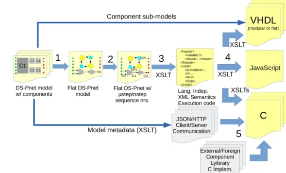
3 – Automatic code generation tools based on the results from 2, generating C, JavaScript and VHDL. The code generated automatically may be used to simulate the model execution, employed in the core of state-space calculation tools [7], but mainly to implement real controllers to deploy on embedded hardware and distributed CPS nodes. A multi-step code generation architecture separates semantics from the target language syntax, simplifying the future creation of code generators for different languages.
4 – The IOPT-Flow Web based integrated development environment, supporting the DS-Pnet formalism, including a graphical editor, a simulator with waveform visualization capability and test automation based on previous stored waveforms, a Petri net model checking sub-system, a remote debugger and automatic distributed code generation tools, among others.
6 – A node-split tool to divide models into sub-models that will run on different distributed nodes, supporting workflows that start with the design of a centralized models, that are simulated and debugged before being split into distributed nodes.
7 – Propose a new mechanism to share the same component among multiple distributed applications, with the definition of two new event properties. Component sharing is transparent for the application models, as if they were being exclusively used.
8 – A growing component library containing both native components (implemented as DS-Pnet models) and foreign components created outside of the IOPT-Flow environment. The foreign library components extend the core functionality of DS-Pnets, with the addition of arrays and matrices, file input and output, random numbers, graphical user interface widgets, audio samples and a communication interface with industrial devices based on the ModBUS communication protocol.
9 – Support for foreign components (in both the C and VHDL code generators), permitting the use of virtually any existing software package or hardware device from DS-Pnet models, building an interface composed of signals and events to invoke code written using other formalisms. This way, existing algorithms, object-oriented classes and hardware subsystems may be integrated in distributed cyber-physical systems in a transparent way.
In addition to the publications listed in the preliminary contributions section, covering the IOPT-Tools framework whose results were applied in this work, new results about the DS-Pnets and the IOPT-Flow tool chain have been published:
1 - Pereira, F.; Gomes, L.; “Combining data-flows and petri nets for cyber-physical systems specification”, Technological Innovation for Cyber-Physical Systems - 7th IFIP WG 5.5/SOCOLNET Advanced Doctoral Conference on Computing, Electrical and Industrial Systems, DoCEIS 2016, Proceedings. Vol. 470 2016. p. 65-76 (IFIP Advances in Information and Communication Technology; Vol. 470) [26]
2 – Pereira, F.; Gomes, L.; "The IOPT-Flow framework pairing Petri nets and data-flows for embedded controller development", IECON 2016 - 42nd Annual Conference of the IEEE Industrial Electronics Society, Florence, 2016, pp. 4832-4837. doi: 10.1109/IECON.2016.7794152 [27]
Publication 1 presents the DS-Pnets and the respective execution semantic rules, publication 2 covers model-checking DS-Pnet models using a controller-plant strategy and the third covers the first validation application presented on chapter 7.
1.7 Document structure
Chapter 2 contains literature review about related topics.
Chapter 3 presents the DS-Pnet modeling formalism, presenting all types of available nodes, arcs and the respective attributes. Focusing on the graphical aspect of the formalism, it presents typical constructions formed by the combination of dataflow operations and Petri net nodes. This chapter also presents a formal definition of the DS-Pnet formalism and the execution semantic rules, leading to the elaboration of a pseudo-code algorithm to execute DS-Pnet models.
Chapter 4 presents details about the automatic code generation tools and algorithms, used to produce code that execute the model semantics for simulation and deployment on embedded hardware.
Chapter 5 discusses the execution of distributed DS-Pnet models containing remote components, communicating over the internet and presents the underlying JSON/HTTP protocol.
Chapter 6 presents the IOPT-Flow tool framework, containing information about the capabilities of each tool and relevant implementation details. A component library and an incipient “standard” library containing foreign components that bring enhanced functionality to DS-Pnet models. This chapter also discusses the available model-checking options and the usage of controller-plant systems to permit the verification of pertinent system properties, without incurring in state explosion problems.
Chapter 7 presents a set of validation applications and discusses the results obtained, comparing with other development languages and tools.
2
Literature Review
This chapter presents a literature survey about related topics. This list is complemented by related work sections on all papers published during the preliminary work and the publications focusing on the DS-Pnet class, that contain references relevant to each specific topic and application examples.
2.1 Petri nets
The Petri net [30][31][72] modeling language, proposed by Carl Adam Petri, frequently used to represent distributed systems, has been widely accepted by the scientific community, referenced by many thousands of research papers from many research areas, including biology, physics, mathematics, business processes, computer science, hardware design and industrial automation. Over the years, many Petri net classes have been created, with extensions for various applications [29][39][40][41][45] [46][73].
The original Petri nets consisted of graphs containing places and transitions connected through Arcs, from which figure 2 presents an example. Arcs starting in a place and ending in a transition are called input arcs and output arcs have origin in a transition and terminate in a place. Places may hold marks, often called tokens, and the state of the system, often called the net marking, consists in the current configuration of tokens hold in all places. State changes occur when a transition fires, consuming tokens from the input places and producing new tokens, added to the output places. A transition may only fire when all places connected through input arcs hold tokens. When this condition holds true, the transition is said to be enabled. Conflicts between several enabled transitions may occur if they share the same input places: if one of the
However, although a transition may be enabled, nothing forces this transition to fire and when multiple transitions are enabled, any of them may (or not) fire. This way, the execution semantics of the original Petri net class is non deterministic. The majority of the net classes derived from the original Petri net class, inherit this execution semantics and are usually used only for simulation. For each Petri net class typically there is a software simulator application, that may be used to perform the so called token-game: enabled transitions are highlighted using a different color and the user may pick the next transition to fire. In alternative, the simulator may choose to fire random enabled transitions and after some time, a graph with the history of recorded markings may be obtained.
2.2 Model checking
Over the years, an entire branch of mathematics has evolved around Petri nets, a sub-set of the general graph theory, and many properties, lemmas and theorems have been studied [31][32][33][46][72][74]. For this purpose, instead of the graphical representation, vector and matrix representations of the Petri net and respective markings are often employed. Figure 3 presents an incidence matrix corresponding to the net on figure 2. Each column correspond to a place and each line to a transition. Negative numbers correspond to tokens removed from inputs places and positive numbers to tokens added to output places.
Fig. 2: Petri net example.
P1 P2 P3 P4 P5 P6 P7 P8 P8N P9
Start -1 1 0 1 0 0 0 0 0 0
Task1 0 -1 1 0 0 0 0 0 0 0
Task2 0 0 0 -1 1 0 0 0 0 0
Wait 0 0 -1 0 -1 1 0 0 0 0
Task3 0 0 0 0 0 -1 2 0 0 0
Lock 0 0 0 0 0 0 -1 1 -1 0
Task4 0 0 0 0 0 0 0 -1 1 1
End 1 0 0 0 0 0 0 0 0 -2
Fig. 3: Incidence matrix
Using the matrix representation, many properties can be verified, including liveness, boundedness, invariants, reversibility, traps and siphons, among many others. Petri net theory textbooks [30][72][75] cover this subject with extensive detail. Using the matrix representation it is also possible to synthesize controllers to impose restrictions that prevent the reachability of undesirable states [76].
Many properties are better analysed using state-space graphs, also called reachability trees. For example, deadlocks and livelocks are easily found on the state-space graph and many reachability problems are usually checked on the state-state-space graphs, with the help from languages like linear temporal logic (LTL) or computational tree logic (CTL) [37][46][77]. Unfortunately, real world applications frequently produce very large state-space graphs, with many milling states. This way, many state-space reduction techniques have been developed and concepts like strongly connected components [38], stubborn sets [78] and other partial order reduction techniques [37] [46], among others.
Most Petri net classes have an associated state-space computation and model-checking tool. Popular model model-checking applications, include the SESA[46][79], Ina/Tina [37], PEP [80], Maria [81], Lola [82], Romeo [83] and PROD [84] tools. The Petri net tool database web page can be consulted for a detailed list [85].
2.3 Execution semantics and non-autonomous properties
embedded system controllers do communicate with the controlled systems (the plant), with the users and the surrounding environment.
To solve these issues, several Petri net classes have been proposed. Among those, the signal/nets systems (SNS) [46][86], the net condition/event systems (NCES) [39], signal interpreted Petri nets (SIPN) [87][88], and Input/Output Place/Transition (IOPT) nets [29] are more referenced in the academic literature. Other formalisms that inherit concepts from the Petri nets, as the Grafcet PLC programming language [65][89] and the signal transition graphs (STG) [90][91] used for digital hardware design, also try to solve these issues.
The signal/event nets and NCES classes employ mixed execution semantics. In these classes, direct connections between transitions may be established using events, forming synchronous channels, where a master transition generates an event received by slave transitions. Master transitions exhibit a spontaneous behavior, similar to the standard Petri net transition semantics, but the slave transitions have a forced semantics, meaning that an enabled slave transition must fire immediately upon receiving an event. This way, the master transitions display an undeterministic spontaneous behavior but the slave transitions obey a maximal step semantics. Some simulation tools may offer a choice of multiple execution semantics to apply to the spontaneous transitions, including random and interleaving transition firing.
To overcome the autonomous nature of Petri nets, some tools and the underlying Petri net classes rely on code segments that may be added to places and transitions. These code segments correspond to procedures written in foreign high level programming languages, as Java [41] and StandardML [40][42], to support mathematical computations, manipulate operating-system resources and perform communication with the external world, including the creation of graphical user interfaces and network communication. Code segments may be executed whenever a transition is fired, when a place receives a new token, or continuously when a place is marked. Theoretically these code segments can read and write interface signals, enabling the creation of embedded system controllers. Unfortunately, the code segments implementing external communication fall outside the scope of the associated model checking tools, that proceed ignoring the effects of such communication operations or simply cannot be applied at all.
inscriptions and process only the standard Petri net components. Many properties can be verified just by inspecting the net topology and the respective matrices or state-space graphs, without considering the inscriptions.
2.4 Low level and high level net classes
Petri nets are usually classified as low level or high level nets [40][41][42], from which the Coloured Petri net class should distinguished as the most well known high level class. The main difference between both types resides on the tokens. Low level tokens carry no data, and places only need to record the number of tokens present. On the opposite, high level tokens can hold variables or even complex data structures: a token can be seen as an object with an associated data type. A low level net can be seen as a particular case of a high level net where all tokens are assigned a void data type.
In the same way as tokens, high level places also have associated data types, corresponding to the types of tokens stored inside. Arcs may be assigned names and mathematical expressions to establish relations between token values. In the same way, transition guards may be used to express restrictions on the token values. Figure 4 displays a simple Coloured Petri net.
Observing figure 4, transition T1 picks two tokens from places P1 and P2 and produces a new token for place P3 with the sum of the two values. The input arcs have inscribed names «a» and «b», used to reference tokens inside places P1 and P2 and the output arc has an expression «a+b» representing the sum of two tokens. In order to fire T1, places P1 and P3 must hold tokens satisfying the guard condition «a <> b», that are removed from the input places and a new token with the respective sum is added to P3. For example, a token with value 21 and another with value 55 may be removed from places P1 and P3, producing a new token with value 76 on P3.
Although the execution semantics of high level Petri nets continues to respect all rules of low level nets, it can be seen as a dataflow, where arcs transport data stored in
places and the transitions perform transformations to the data. This characteristic represents an enormous value for embedded system controller design, and some authors have employed high level nets for this purpose [42][56][92].
As an example, an industrial production line can be modeled using high level nets. Individual parts travel on a conveyor belt and multiple machines may apply operations on those parts. The parts can be modeled using tokens, containing information about each part, as the serial number and the types of operations that must be performed. Each machine may be modeled using a transition, that applies transformations to the tokens according to the operations performed on the physical parts. Buffer zones that store parts waiting to be processed may be modeled by places that store tokens.
2.5 High level net execution strategies
When the token data types are restricted to very small sets of colors, it is possible to unfold an high level net into an equivalent low level net [93][94], that although larger, can be processed with the standard low-level Petri net tools, including automatic code generators. However, when the cardinality of the data types employed is larger, this technique results in an explosion on the size of the resulting low level nets that would be impractical. For instance, if the integer numbers used in the figure 4 example, were limited to a simple 8bit (byte) data type, the resulting low level net would contain 65280 transitions. If 16 bit integers were used, then 232–216 transitions would be
required.