Braz. J. of Develop., Curitiba, v. 6, n. 7, p. 53369-53392 jul. 2020. ISSN 2525-8761
Heat rejection avoidance in combustion engines
Evitar a rejeição de calor em motores de combustão
DOI:10.34117/bjdv6n7-835Recebimento dos originais: 03/06/2020 Aceitação para publicação: 30/07/2020
Wagner Santos Matos
Formação acadêmica mais alta: Doutor em Engenharia Mecânica, Engine Engineering Supervisor Instituição: Universidade Estadual Paulista Júlio de Mesquita Filho, Faculdade de Engenharia de
Guaratinguetá – UNESP/FEG
Endereço: Av. Ariberto Pereira da Cunha, 333 – CEP:12516-410 – Guaratinguetá/SP (pode ser institucional ou pessoal, como preferir)
E-mail: Wagner.Santos1@volkswagen.com.br
Juliano de Assis Pereira
Highest graduation degree: MBA
Institution / University: Fundação Getulio Varga Adress: Gebrüder-Kaulich Strasse, 10, Haus G. Steyr, Austria.
E-mail: Juliano.pereira@man.eu
Josef Klammer
Highest graduation degree: Dipl.-Ing. (FH)
Institution / University: MAN Truck & Bus Österreich AG Adress: Schönauerstraße 5, 4400 Steyr
E-mail: Josef.Klammer@man.eu
José Antonio Perrella Balestieri
Formação acadêmica mais alta: Professor Titular Doutor em Engenharia Mecânica Instituição: Universidade Estadual Paulista Júlio de Mesquita Filho, Faculdade de Engenharia de
Guaratinguetá – UNESP/FEG
Endereço: Av. Ariberto Pereira da Cunha, 333 – CEP:12516-410 – Guaratinguetá/SP E-mail: jose.perrella@unesp.br
Alex Mendonça Bimbato
Formação acadêmica mais alta: Professor Assistente Doutor em Engenharia Mecânica Instituição: Universidade Estadual Paulista Júlio de Mesquita Filho, Faculdade de Engenharia de
Guaratinguetá – UNESP/FEG
Endereço: Av. Ariberto Pereira da Cunha, 333 – CEP:12516-410 – Guaratinguetá/SP E-mail: alex.bimbato@unesp.br
Marcelino Pereira do Nascimento
Formação acadêmica mais alta: Professor Associado Doutor em Engenharia Mecânica Instituição: Universidade Estadual Paulista Júlio de Mesquita Filho, Faculdade de Engenharia de
Guaratinguetá – UNESP/FEG
Endereço: Av. Ariberto Pereira da Cunha, 333 – CEP:12516-410 – Guaratinguetá/SP E-mail: marcelino.nascimento@unesp.br
Braz. J. of Develop., Curitiba, v. 6, n. 7, p. 53369-53392 jul. 2020. ISSN 2525-8761 ABSTRACT
Heat rejection to a cold reservoir is inherent of thermal machines operation. One of them, the engine cycle, aims to deliver liquid power and its efficiency increases directly proportional to the hot reservoir and inversely proportional to the cold reservoir. Most of the studies for increasing engine efficiency leads to increase the hot reservoir. This research instead, instigates the discussion of a better use of energy and heat rejection avoidance on internal some combustion engines systems. It demonstrates the principle that the heat rejection improvement using liquid instead of air ran against the real objective that should have been using it better. The paper shows feasible design steps with physical, energetic and economical approach to implement an engine gas recirculation system, which uses tail pipe gases, through a supersonic Laval nozzle parallel to intake line after charge air cooler. It also purposes waste heat recovery from engine liners as heat source for a Rankine cycle. All calculus and simulations are done based on a real engine data submitted to an European Transient Cycle.
Keywords: ORC. Liners, Super Heater, Supersonic, EGR, Heat Recovery, Cooling. RESUMO
A rejeição de calor a um reservatório frio é inerente à operação de máquinas térmicas. Um deles, o ciclo do motor, visa fornecer energia líquida e sua eficiência aumenta diretamente proporcional ao reservatório quente e inversamente proporcional ao reservatório frio. A maioria dos estudos para aumentar a eficiência do motor leva ao aumento do reservatório quente. Esta pesquisa, em vez disso, instiga a discussão de um melhor uso da energia e evitar a rejeição de calor em sistemas internos de alguns motores de combustão. Ele demonstra o princípio de que a melhoria da rejeição de calor usando líquido em vez de ar corria contra o objetivo real que deveria estar usando melhor. O documento mostra etapas viáveis de projeto com abordagem física, energética e econômica para implementar um sistema de recirculação de gás de motor, que usa gases de escapamento, através de um bico supersônico Laval paralelo à linha de entrada após o resfriador do ar de sobrealimentação. Ele também propõe a recuperação de calor residual dos revestimentos do motor como fonte de calor para um ciclo Rankine. Todos os cálculos e simulações são feitos com base em dados reais do motor submetidos a um ciclo transitório europeu.
Palavras-Chave: ORC, Forros. Super Aquecedor, Supersônico, EGR, Recuperação de Calor,
Resfriamento.
1 INTRODUCTION
The studied engine is an inline 4 cylinder, 4,5 liter, 4 stroke, turbocharged, water cooled, reciprocating diesel engine. It uses overhead valves and a common rail with 1800bar injection pressure for compression ignition (Figure 1). The choice of a 4 cylinder engine for this study was due to high load factor that this hardware is subjected to. As it leads to a high heat rejection amount, in terms of percentage, it is expected to reach more energy recovery than on a 6 cylinder engine with higher volume and lower load factor. In addition, the choice is also strategically better, since low packaging available will protect the design for bigger Engines. The base data for this study was obtained from a ETC objective measurement.
Braz. J. of Develop., Curitiba, v. 6, n. 7, p. 53369-53392 jul. 2020. ISSN 2525-8761
Figure 1: Engine baseline for study
The most common waste heat recovery studies are related to the exhaust gases. For example, BORGWARNER, (2014) uses an organic Rankine cycle with exhaust pipes and engine recirculation systems as main Energy sources. CUMMINS, (2008) presented a complete study in the 2008 DEER (Diesel Engine Efficiency Emissions Research) demonstrating through test benches analysis that it would be possible to decrease the fuel consumption in ca. 10% by using organic Rankine cycle to recover energy from exhaust gas streams. However, with the current legislation EURO 5-CONAMAP7, resolution 403/2008, and the new legislation EURO 6 (current in EUROPE), the opportunity to use this energy is getting lower because the after treatment emissions processes are demanding high temperatures to allow the chemical reactions that decreases emissions level.
Based on a real engine measurement submitted to an ETC cycle, it is possible to notice that a high amount of energy is lost through the cooling process. As soon as a conventional Rankine Cycle shows efficiency about 30 % and assuming to recover 10% of the energy lost on the cooling system, the heat balance for the actual proposal is capable to recover up to 10 kW of liquid power.
A mathematical analysis has been performed using GT Power software enable simulations of different kind channels profiles and disposition around combustion chamber. For the EGR system without EGR cooler, a complete ETC cycle was calculated with Excel and VB. It was possible do demonstrate that the use of an supersonic Laval nozzle would be a feasible solution for mixing gases from low pressure line to the high pressure line on intake clean air flow.
The super heater for the Rankine cycle will assume some the dimensional boundary conditions from the available engine. As the conduction area will be decreased on the liners
walls (Figure 9), the heat transfer area “lost” for the forced convection cavities will need to be compensated in order to keep the internal combustion chamber temperature.
Braz. J. of Develop., Curitiba, v. 6, n. 7, p. 53369-53392 jul. 2020. ISSN 2525-8761
The application of this mechanism brings potential to suppress the conventional cooling system or at least downsize it. The concept of this super heater is developed together with the definition of a fluid that matches the proposed Rankine cycle.
The energy recovered using this system, converted into decrease of fuel consumption, will need to overcome the investments to worth it the Customer TCO (Total Cost of Ownership).
The development of this energy recovery system is being supported from a known commercial vehicle OEM in Brazil. All theory studies were done using a 4.5 Liter Engine.
2 GENERAL INFORMATION
All results presented in this chapter are based in a real ETC cycle of an 4 cylinder 4.5 liter diesel engine that is currently in production. Circa of 18.000 measurement points were analyzed. No confidential strategy data is showed in the results and the specific know how is registered on the patent request number BR102019002884.
2.1 BASELINE ENGINE ENERGY CONSUMPTION
Thermal machines presents low efficiency. Reciprocating combustion engines are not different and heat is wasted on the conversion of the chemical energy into mechanical. The most explored recovering alternatives are related to the exhaust gases, but this work intends to demonstrate the feasibility of recovering energy from the cooling system, that is nowadays it is barely explored from scientific community.
An interesting way to observe the heat balance is analyzing the complete vehicle. [2] describes it in his paper and concludes that ca. of 62% of the fuel demand is converted in Themal Energy (Figure 2), which, nowadays is wasted. This is exactly why the researches about WHR are so intensive at this moment.
Braz. J. of Develop., Curitiba, v. 6, n. 7, p. 53369-53392 jul. 2020. ISSN 2525-8761
Figure 2: Vehicle Energy flow diagram, Hay, et. al., 2011
For the engine in study, the coolant system rejects less heat. Figure 3 organizes the energy distribution showing the corresponding spent at cruise speed of 1750 rpm with full load. It shows that 28% from the Energy generated by the fuel combustion is rejected through the radiator.
28% of rejection on the radiator corresponds to 105 kW. This is the result of the calculation based on the inlet and output temperatures of the Charge Air Cooler (CAC). For the current situation, the relation Q = m.c.∆T is determinated from:
Figure 4: Cooling cycle [32]
QRad = Energy rejection on the Radiator (28% of the fuel energy generation) = 105 kW
Q = QH = 105 kW
m = 270 kg of coolant per minute
c = 3,74 kJ/kg.K (From coolant at working temperature – data provided from supplier)
∆T = 6,2 K
It is important to notice that at this point (CAC), the coolant flows at high rates, which leads to a high surface coefficient on forced convection. This convection receives the heat from engine coolant chamber also at high rates. On this region (around liners) the temperature gradient is extremely high showing a big chance of waste heat recovery.
2.2 HEAT RECOVERY FROM LINNERS
As the research assumes the combustion chamber temperature as an important boundary condition, the heat transfer flow must kept, as well as the material behavior due to thermal fatigue.
Braz. J. of Develop., Curitiba, v. 6, n. 7, p. 53369-53392 jul. 2020. ISSN 2525-8761
With this system, it is possible to generate work using the engine liners as a steam generator for a Rankine cycle. A side effect will also be noticed: it possible at least to downsize the original cooling system or even suppress it.
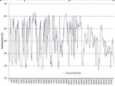
Figure 5 shows that the average temperature from exhaust gases are around 405oC reaching
peaks of 630oC. The exhaust manifold itself reaches temperatures above 500oC.
Figure 5: Temperature from exhaust gases before turbocharger
Figure 6: Temperature around the exhaust gases flow inside engine
Analyzing the cylinder walls, the path of the exhaust gases and its heat transfer to the coolant
is showed in Figure 6. The Bottom Dead Center (BDC) wall temperature is considered 1000C and the
highest temperature of 5000C is the contact between exhaust manifold and engine head. This path means the complete flow of exhaust gases inside the engine (crankcase and cylinder head). Notice that there is not a linear model to simulate forced convection from Exhaust gases to cylinder wall and from cylinder wall to the coolant. The cylinder temperature gradient needs to be considered on the simulation.
Braz. J. of Develop., Curitiba, v. 6, n. 7, p. 53369-53392 jul. 2020. ISSN 2525-8761
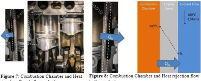
Notice in Figure 7 that the combustion chamber walls faces a permanent energy flow that comes from the chamber to the coolant galleries. The combustion chamber walls can reach
temperatures up to 250oC. As the coolant evaporation temperature is around 1100C on the max system pressure, the external chamber wall cannot be over this temperature (TS). The estimated temperature distribution through the liners walls in a specific thickness position is shown in Figure 9. Assuming that the engine combustion chamber temperatures cannot be impacted from the project, the chamber heat extraction must always be kept independently on the way it is extracted from the walls. If QS could eventually assume the QH value, it would mean completely suppressing the conventional coolant system. This schema is part of the hole project conclusion and can be seen in Figure 29. The heat extraction from engine liners will be limited by the heat rejection from the material and channel profile used around the liners (heat exchanger). The construction of the super heater would also influent on the heat transfer. The concept of a liner with internal channel could Figure 9.
Braz. J. of Develop., Curitiba, v. 6, n. 7, p. 53369-53392 jul. 2020. ISSN 2525-8761
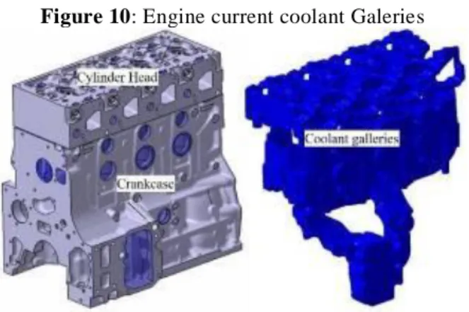
To evaluate if an alternative heat extraction could eventually substitute the complete cooling system, an analysis of the coolant galleries was performed. The engine coolant galleries are represented in Figure 10.
Figure 10: Engine current coolant Galeries
Assuming the engine as a control volume, the mass flow (in/out) is 270kg per min. It flows constantly through the galleries with a complete heat exchange surface of 4,4 m2. Despite the losses through convection around the engine and periphery, the heat transferred to the coolant in the engine in study is 105 kW which would mean roughly 23,86 kW per m2. It is clear that not all the surface is in contact with a high heat source, but considering the turbulence and high speed flow, this estimation is a confident value for the objective in discussion.
Braz. J. of Develop., Curitiba, v. 6, n. 7, p. 53369-53392 jul. 2020. ISSN 2525-8761
For the simulation, round section channels (Figure 11) were considered around the liners with thermal conductivity equal to the current crankcase cast iron. The heat transfer with phase transfer inside a circular tube is defined by [24]:
Figure 12: Liner temperature profile
Figure 13: Convection correlations for flow in a circular tube [21]
The liner temperature profile is showed in Figure 12. The OEM design proposal for the super heater itself cannot be yet shown in this thesis due to rights protection, but the simulations confirm the feasibility of this proposal, which has already been tried and registered on other patents [23]. The consideration for internal flow into circular tubes are based on Figure 13.
Braz. J. of Develop., Curitiba, v. 6, n. 7, p. 53369-53392 jul. 2020. ISSN 2525-8761
Using the GT Power software with application of the chosen geometry and premises, 7 different scenarios were simulated trying to find a way to get super-heated fluid on the liners output. All cases were analyzed considering the cast iron thermal conductivity, ethanol as working fluid, same distance between the channels rings, 10 bar of pressure input, 800C of temperature input, 400 discretization steps and same liner diameter. The term channel geometry is a composition or channel diameter with distance to chamber wall;
Figure 14: Liner evaporator: Case 1 [39]
Figure 14 shows case 1, which considered channel geometry 1 (R=68,5 mm and channel diameter of 3,5 mm). The mass flow is 1g/s. The simulation showed a laminar flow and low pressure loss, but low heat transfer (0,2 kW) and no evaporation.
The case 2 uses the same channel geometry from case 1, but higher mass flow (2g/s). The result was an almost completely evaporated output (1,74 kW). 9.9 bar output.
The case 3 used the same geometry from case 2, but increased mass flow to 5g/s. It resulted in less evaporation than case 2 (approximately 42%), but had a high heat output absorbed by the working fluid (2.61 kW). It would be an interesting condition to work in series downstream of one next evaporator. For example post after treatment system.
The case 4 can be good compared with 2, since the mass flow is also 2g/s and just the channel diameter was changed to 3 mm (Channel geometry 2). It leaded to a slightly better heat exchange (1,84 kW), but increased pressure drop (9,7 bar).
Braz. J. of Develop., Curitiba, v. 6, n. 7, p. 53369-53392 jul. 2020. ISSN 2525-8761
The case 5 increases mass flow to 5g/s keeping geometry 2. It improved heat exchange (2.67 kW at output) but showed higher pressure drop (9.1 bar output).
The case 6 is better comparable with case 4 because it changes just wall thickness to chamber assuming the channel geometry 3 and mass flow. It was noted a sensible improvement in heat transfer (1,94 kW) and complete phase change with superheated outlet. This condition is indicated for installation of expander in series upstream evaporator.
The case 7 kept channel geometry 3 and, in relation to case 6, the mass flow is increased to 3 g/s. A sensible improvement of heat transfer was observed.
Heat transfer ability increases progressively on the seven simulated steps, showing the influence of the channel geometry as well as the mass flow ratio.
Based on the data from case 7, the spring profile around the liners presents a 13,7 m long tube with 3 mm diameter and total shell area of 0,13 m2. Considering the total heat transfer ability of 2892 W, the heat extraction is 22,2 kW/m2.
Smaller channels diameter improves heat transfer at low and medium mass flows due to turbulent flow. Low wall thickness improves heat absorption of the working fluid, limitation by material strength. Liner evaporator is suitable for generation of steam or mixed steam for subsequent superheating in other evaporator in series. Considerable heat absorption into the working fluid. Smaller channels diameter increases pressure loss, especially in the superheated area. Limitation by the permissible wall temperature prevents overheating at higher pressures.
The mathematical model was simplified for a round section in order to use existing empirical data, but improvements on the profile and use of better conductivity materials can increase the potential transfer ability.
The evaporator to run a Rankine cycle must fulfill the dimensional boundary conditions from the available engine liners. As the conduction area will be decreased on the liners walls, like showed in the model from Figure 9, the heat transfer area “lost” for the forced convection cavity needs to be dimensioned in a way to compensate the Heat extraction from combustion chamber. This situation can potentially mean QH = QS (Figure 9) and is necessary to keep the internal combustion chamber temperature.
The working fluid for the purposed Rankine cycle shall be ideally the same from the cooling system, which shall be easily available on the market. Nevertheless, the fluid that matches this requirement (ethanol), brings a lot of concerns regarding safety of the system.
The use of ethanol in a Waste Heat Recovery (WHR) system from the OEM shows corrosion and performance effectiveness to support the decision of using it in a OCR cycle. A system, at this
Braz. J. of Develop., Curitiba, v. 6, n. 7, p. 53369-53392 jul. 2020. ISSN 2525-8761
moment not integrated to the cooling, is now running tests, but unfortunately the specifications and safety features are non-disclosure at the moment.
With the definition of the cycle fluid, one positive displacement pump needs to be specified in order to control the working fluid flow and an expander can be defined based on the reached steam generation obtained from the mathematical model.
The application of a system able to recovery energy from the cooling system has potential to substitute the conventional cooling system or at least downsize it. The concept of this super heater allows the application of an WHR without need of extra installation package that is one of the biggest challenges on the existing WHR vehicle proposals.
2.3 COLD ENGINE GAS RECIRCULATION SYSTEM
Using the exhaust gases parameters combined with the measured temperatures T_AGR_VK and T_AGR_NK (Figure 15), the first penalty on the energy balance is a consumption of 19,5 kW to cool down the exhaust gases before it comes back into the intake line. The second energy penalty it that the Exhaust gases that could be used for performance on the turbocharger are drained to supply the Engine Gas Recirculation (EGR) demand. It causes an intangible loss of performance when the gases that could drive the turbocharger are used to come back into intake line. This side effect is not calculated in this thesis.
Figure 15: Measurement points from the ETC cycle [17]
EGR systems are used to decrease combustion temperature at specific engine loads and consequently the NOx emissions. The Figure 16 shows the EGR demand in comparison with the
Braz. J. of Develop., Curitiba, v. 6, n. 7, p. 53369-53392 jul. 2020. ISSN 2525-8761
engine intake fresh air. The EGR system from the base line engine (Figure 17) uses the inert gases from the exhaust manifold before the turbocharger. This point is directly connected to the intake manifold and on its way there is a control valve and a heat exchanger that decreases the exhaust gases temperature before mixing it with the fresh air.
In a conventional 4 cylinder Diesel Engine, decreasing exhaust gases temperatures from
6000C to 1000C can mean a sensitive loss of energy. Some concepts has been developed to decrease the inlet temperature, but most of them stops on the presence of particulate on the turbocharger compressor wheels.
The present work purposes a high flow variable valve to mix exhaust gases from vehicle tail pipe (lower possible temperature) with the pressurized fresh air on the intake line (after turbocharger) either before or after Charge Air Cooler (CAC). In order to study the possibility to the mix the low pressure line (Exhaust gases) with the high pressure line (fresh air), one ETC cycle measurement from the base line engine was done.
Notice that the EGR demand reaches picks of 30% of complete intake air, but sensitively varies on the engine working cycle. The EGR rate average, in comparison with fresh air for the ETC cycle from Figure 16, is 19,27%.
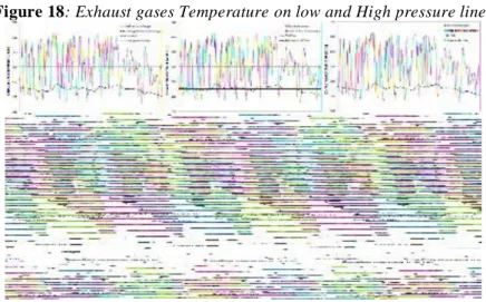
Based on the data from Figure 18 it is possible to calculate that the average temperature
before the turbocharger is 403oC reaching picks of more than 6000C. As it is necessary to spend energy to cool down those gases, an obvious solution for that would be capturing the exhaust gases from a lower temperature point. In a combustion engine vehicle, this point is known as tail pipe,
which, in this case, reaches temperatures lower then 300oC maintaining an average of 253oC as showed in Figure 18.
Braz. J. of Develop., Curitiba, v. 6, n. 7, p. 53369-53392 jul. 2020. ISSN 2525-8761
Figure 18: Exhaust gases Temperature on low and High pressure lines
Taking inert gases from this point would mean directly a 40% decrease of the EGR system
heat rejection: (4030C x 2530C)
Even the fuel consumption reduction estimation are not simple, if 6 kW heat rejection avoidance could be directly converted in useful power, it would mean 3,5% of the 164 kW power from the engine in study.
Unfortunately taking the inert gases from the tail pipe is not an easy task. Alternatives like Low Pressure EGR are possible solution, but the contact from the particulate with the compressor wheel from turbo charger are not desirable. The technical requirement for durable systems are very expensive and doesn´t worth it taking the EGR cooler out from the system. Therefore, the proposal from this work is taking the inert gases from the tail pipe and mixing it with fresh air after the turbocharger compressor.
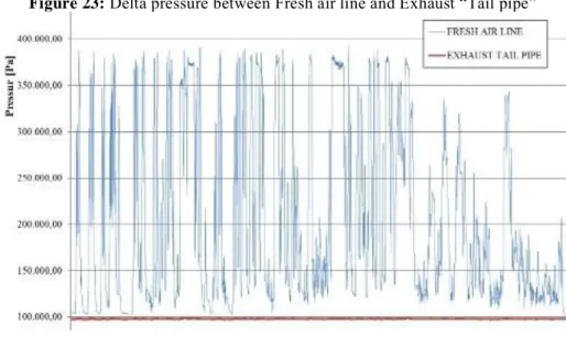
In Figure 19, it is possible to understand how different are the pressures from the tail pipe line and the fresh air line after turbocharger compression. Notice that more than 60% from 18.000 delta pressure points measured in this ETC cycle are under 1 bar. The remaining measured points works on 2bar or 3bar difference, 20% each.
Braz. J. of Develop., Curitiba, v. 6, n. 7, p. 53369-53392 jul. 2020. ISSN 2525-8761
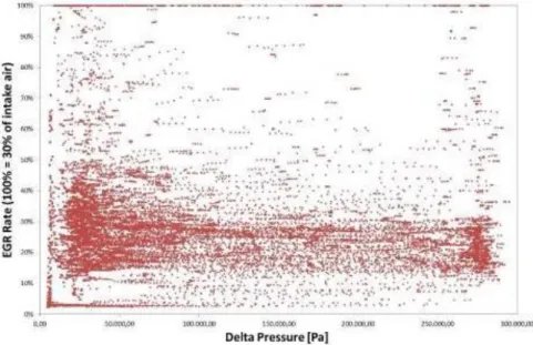
At the same time that the delta pressure is not constant, the EGR demand are also not. In Figure 20 the EGR demand 100% means 30% of the engine complete intake (fresh air + Recirculated gases).
Figure 20: EGR demand distribution
The combination of delta pressure and EGR demand is shown in Figure 21. A mechanism to mix those pressure lines must be developed to mix 100% of EGR demand
Braz. J. of Develop., Curitiba, v. 6, n. 7, p. 53369-53392 jul. 2020. ISSN 2525-8761
As the Bernoulli principle works for all situations were uncompressible air flow increases, a system was designed to allow pressure drop by increasing air speed just when exhaust gases are necessary. This design enables the system to decrease the heat rejection in about 9kW, what means ca of 40% heat rejection avoidance.
The Figure 22 shows the temperature that would result from the mixture of the fresh air directly with the tail pipe exhaust gases. Note that this configuration does not consider recuperation of any energy post after treatment system. If such system is considered in parallel, the exhaust gases would have even lower temperatures.
Figure 22: Temperature after mixing lines
A conventional VENTURI system uses the Bernoulli principle increasing the flow speed in order to decrease the flow pressure and consequently mix the low pressure (Exhaust Tail pipe) with high pressure (Fresh Air) lines. The Figure 23 shows the involver pressures.
Braz. J. of Develop., Curitiba, v. 6, n. 7, p. 53369-53392 jul. 2020. ISSN 2525-8761
To reach 3 bar reduction on the fresh air intake line, it would be necessary to reduce the cross section in more than 50%. As can be observed in Figure 21, the full EGR demand is not necessarily coincident with high delta pressure demands, which leads to the conclusion that a conventional VENTURI installed in the intake line would cause unnecessary pressure drop throughout the engine map.
To avoid this condition, a “variable venture” concept was created. In Figure 24 there is a control valve on the fresh air track which controls the back pressure in order to derivate the flow to the line where the Venture is located. With this action, when EGR is not necessary, the control valve opens and the fresh air flows with no restriction.
Figure 24: Variable Venturi
For stationary conditions the pressure drop can be calculated as follows:
[1]
Although [22] shows that the venture equations are representative just for uncompressible flow. The identification of this transition is determinate by the flow speed. In Figure 25 both situations are showed.
Braz. J. of Develop., Curitiba, v. 6, n. 7, p. 53369-53392 jul. 2020. ISSN 2525-8761
Figure 25: Subsonic and supersonic flow behavior [22]
Mach (M) is the number defined by the division from the current speed by the sound speed. This parameter leads to calculations for compressible flow in some points of the engine map in study. Notice in Figure 26 that the pressure drop between fresh air line and tail pipe cannot reach values over 1,5 bar. Over this limit, the speed inside the venture overcomes sound speed and its behavior cannot anymore be modelled with the conventional venture theory. There is also a risk of inverting the behavior. It means that instead of lowering the pressure, it could be even higher, like showed in Figure 25.
Figure 26: Pressure drop limit using uncompressible fluid equations
To overcome the technical restriction imposed from the uncompressible flow, the purposed system had the conventional venture concept substituted by a supersonic Laval nozzle that can be observed in Figure 27. It consists in a system which drops pressure and increases flow velocity. This
Braz. J. of Develop., Curitiba, v. 6, n. 7, p. 53369-53392 jul. 2020. ISSN 2525-8761
system is commonly used in aircraft jet engines to increase speed. When the fluid starts a supersonic flow on the throat, the pressure drop will appear right after the throat and not directly on it.
Figure 27: Laval nozzle temperature, pressure and velocity behavior [44]
The calculation point by point on the ETC cycle shows that a Laval nozzle completely in series with the fresh air flow would need through diameters that varies between 13 mm and 21 mm. As the with 13 mm, the pressure drop is already enough to fulfill the hole map from Figure 21. Therefore, the project was dimensioned to reach M=1 on the throat at lowest air available intake flow. In Figure 28 it is possible to see the purposed supersonic Laval nozzle cross section and channels for the exhaust gases admission.
Braz. J. of Develop., Curitiba, v. 6, n. 7, p. 53369-53392 jul. 2020. ISSN 2525-8761
2.4 CONSOLIDATED SYSTEM
With a cold EGR and an evaporator around liners able to substitute the conventional cooling system, a complete new system shows feasibility to be built and can be observed in Figure 29.
Figure 29: Heat rejection avoidance system (complete)
The ETANOL would substitute the old coolant as working fluid. The CONDENSER would work in place of the old coolant radiator. The RECUPERATOR would be a heat exchanger liquid x air that would substitute the old charge air cooler air x air. The EVAPORATOR around the engine heat sources would substitute the complete engine coolant galleries.
3 CONCLUSION
EGR heat rejection was 19,5 kW with a delta temperature of 323 K (403-80). As this delta drops to 173k (253-80), the energy spent would be 10,4 kW, what means a heat rejection avoidance of 9,1 kW. It can be converted in a smaller radiator for the old system or to a smaller condenser on the purposed new one.
The conventional coolant system rejects 23,86 kW/m2 with coolant and the mathematical model of a evaporator with simple round cross section is able to extract 21,5 kW/m2. It was demonstrates that the coolant system can be completely substituted by evaporators around the “hot spots” in the engine. It would mean transferring 105 kW to the ORC working fluid.
By changing the dry charge air cooler to a wet one using the same ethanol line on it would mean extra 23,4 kW (measured data) transferred to the ORC for WHR.
WHR potential = (105 kW – 19,5kW) + (23,4 +10,4kW) = 119,3 kW
Conventional Rankine cycles doesn´t use to have more than 30% of efficiency. If this system can be able to recover between 10% and 30% of it, it would mean between 12 kW and 36 kW back to the power line. I would easy represent extra 10% of extra power or 10% less diesel consumption.
Braz. J. of Develop., Curitiba, v. 6, n. 7, p. 53369-53392 jul. 2020. ISSN 2525-8761
Note that the system has potential to be cheaper than the old system and will include one extra function: the heat recovery. Today the expander cannot still be clearly priced because there wasn’t until now large scale production of it. As constructively, it doesn´t differ a lot from an air conditioning compressor, it should not cost more than 50% more than the known part.
REFERENCES
[1] AJdesigner, https://www.ajdesigner.com/venturi/venturi_pressure_differential.php, access at Oct, 2016
[2] B. Hay, J. Hameury, V. Scoarnec, G. Davée and M. Grelard Laboratoire National de Métrologie et d’Essais 29, avenue Roger Hennequin, 78197 Trappes Cedex, France
[3] Baatar, N., Kim, S., A Thermoelectric Generator Replacing Radiator for Internal Combustion Engine Vehicles, TELKOMNIKA, Vol.9, No.3, pp. 523~530, ISSN: 1693-6930, 2011.
[4] Bandivadekar, A., Bodek, K, Cheah, L., Evans, C., Groode, T., Heywood, J., Kasseris, E., Kromer, M. Weiss, M. On the Road in 2035: Reducing Transportation’s Petroleum Consumption and GHG Emissions, Laboratory for Energy and the Environment
[5] Bandivadekar, A.; Bodek, K.; Cheah, L.; Evans, C.; Groode, T.; Heywood, J.; Kasseris, E.; Kromer, M.; Weiss, M. On the Road in 2035: Reducing Transportation’s Petroleum Consumption and GHG Emissions, Laboratory for Energy and the Environment, Report No.
LFEE 2008-05 RP, Massachusetts Institute of Technology, July 2008
[6] Borg Warner Emission Systems, R&D project: Rankine System Waste Heat Recovery, Internal Presentation, 2014
[7] Callister, W.D.; Retwish, D.G. Ciência e Engenharia dos Materiais: uma Introdução. 8ª Edição, LTC, 2013
[8] Camargo, J. R, Oliveira, M. C. C. Projeto de um condicionador de ar automotivo peltier-seebeck autossustentável. 2010. VI National Congress of Mechanical Engineering,
Campina Grande, Paraíba, Brazil
[9] Cibsejournal, Module 10: Absorption refrigeration, document dates from 2009, https://www.cibsejournal.com/cpd/modules/2009-11/, access at May, 2019
[10] Cipollone, R. Di Battista, D., Gualtieri, A., Turbo compound systems to recover energy
[11] CUMMINS, 2008, Exhaust Energy Recovery, 2008 DEER Conference, 2008
[12] Easyautocooling, Copyright©2008, Disponível em:
http://www.easyautocooling.com/engine-cooling Consultada em Dez.2016
[13] Esapyronics, VENTURI MIXERS - FLOMIXERS SERIES, Bulletin E2301 rev04, 2001, http://www.esapyronics.com/wp-content/uploads/2014/12/E2301E.pdf, access at May 2017.
[14] ESCALANTE, E. S. R. Estudo dos limites de inflamabilidade em mistura etanol-ar- diluente, 2016, Dissertação apresentada à Faculdade de Engenharia do Campus de Guaratinguetá, Universidade Estadual Paulista, para obtenção do título de Mestre em Engenharia Mecânica na área
Braz. J. of Develop., Curitiba, v. 6, n. 7, p. 53369-53392 jul. 2020. ISSN 2525-8761
de Energia, Faculdade de Engenharia de Guaratinguetá, Universidade Estadual Paulista, São Paulo, Brasil.
[15] FERREIRA, E. M. F. Dimensionamento das capacidades da caldeira a vapor e torre de resfriamento para o sistema de utilidades de uma planta química. 2012, Trabalho de Conclusão de Curso apresentado à Escola de Engenharia de Lorena da Universidade de São Paulo, Curso de Engenharia Industrial Química, Lorena, São Paulo, Brazil
[16] GARCIA, M. B. Características do desgaste de anéis de pistão com diferentes tecnologias de tratamentos superficiais, 2003, Dissertação apresentada como parte dos requisitos para obtenção do Grau de Mestre em Ciências na Área de Tecnologia Nuclear- Materiais, IPEN, Autarquia associada à Universidade de São Paulo, São Paulo, Brazil.
[17] Gohm, L, Test bench mearurement points, MAN Trucks and Buses, 2016
[18] Goncalves, L.M., Martins J., Antunes J., Rocha, R., Brito, F.P., Heat-pipe assisted thermoelectric generators for exhaust gas applications, ASME 2010 International Mechanical Engineering Congress & Exposition, 1387–1396, 2010.
[19] Heywood, John B.L. INTERNAL COMBUSTION ENGINE, McGraw-Hill, Inc, 1988 Imagem do motor (5Cs): https://www.quora.com/What-is-the-location-of-connecting-rod-in- an-IC-engine
[20] ICE, International Journal of Engineering and Innovative Technology (IJEIT), Volume 3, Issue 6, 2013.
[21] Incropera, DeWitt, Bergmann, Lvine, Fundamentals of Heat an Mass Transfer, 2006.
[22] Inecropera, F.P.; DeWitt, D.P. Fundamentos de Transferência de Calor e Massa, 4ª Edição. LTC, 1998
[23] Jörg, M., 08538, Verbrennungsmotor mit doppelwandiger Laufbuchse und Abgaswärmetauscher zum Erhitzen, Deutsches Patent- und Markenamt, DE 10 2012 015 927 A1, 2014
[24] Kandlikar, S. G., J. Heat Transfer, 112, 219, 1990
[25] Kim, J, Bae, C, Emission reduction through internal and low-pressure loop exhaust gas recirculation configuration with negative valve overlap and late intake valve closing strategy in a compression ignition engine, International J of Engine Research, Vol. 18 (10), Pages 973–990, IMechE, 2017
[26] Kim, S., Park, S., Kim, S. et al. Journal of Elec Materi (2011) 40: 812. doi:10.1007/s11664-011-1580-6
[27] KUNTE, B. Thermodynamic, economic and emissions analysis of a micro gas turbine cogeneration system operating on biofuels. 2015. 101 p. Dissertation (Master in Mechanical Engineering) - Faculty of Engineering of Guaratinguetá, São Paulo State University, Guaratinguetá, 2015.
[28] LOUREIRO, T. W. Análise paramétrica do conjunto pistão, biela e árvore de manivelas com foco na redução de perdas por atrito e consumo de combustível. 2009, Trabalho de Conclusão de Curso apresentado à Escola Politécnica da Universidade de São Paulo para obtenção do Título de Mestre Profissional em Engenharia Automotiva, São Paulo, Brazil.
[29] MARTINELLI JÚNIOR, L. C. Sistema de Ar Condicionado por Absorção para Ônibus. Guaratinguetá, 2008. Tese (Doutorado em Engenharia Mecânica) – Faculdade de Engenharia –
Braz. J. of Develop., Curitiba, v. 6, n. 7, p. 53369-53392 jul. 2020. ISSN 2525-8761
Campus de Guaratinguetá, Universidade Estadual Paulista, São Paulo, Brazil.
[30] Orr, B.(a), Akbarzadeh, A.(a), Mochizuki M.(b), Singh, R.(b) A review of car waste heat recovery systems utilising thermoelectric generators and heat pipes, (a) RMIT University, Bundoora, Victoria, Australia; (b) Fujikura Ltd, Kiba, Tokyo, Japan. Applied Thermal Engineering 101 (2016) 490–495.
[31] PEDERIVA, A. C., MATTIONI, R., MICHELS, A. Dimensionamento de uma tubulação de vapor para uma fabrica de ração animal. 2013, 3ª Semana Internacional das Engenharias da Fahor, Horizontina, Rio Grande do Sul, Brazil
[32] Ploucha, R; Ainsworth, A. Rankine cycle layout.png. 29. Nov 2007 Disponível em: http://commons.wikimedia.org/wiki/File:Rankine_cycle_layout_PL_w_gen.png Acesso em Jan. 2015
[33] REJOWSKI, E. D. Caracterização e desempenho de um filme de carbono amorfo hidrogenado tipo diamante (a-C:H) dopado com silício, aplicado em camisa de cilindro de motor a combustão interna. 2012, Dissertação apresentada como parte dos requisitos para obtenção do Grau de Mestre em Ciências na Área de Tecnologia Nuclear – Materiais, Instituto de pesquisas energéticas e nucleares, autarquia associada à universidade de São Paulo, São Paulo, Brazil.
[34] Report No. LFEE 2008-05 RP, Massachusetts Institute of Technology, 2008
[35] SANTOS, A. J. P. Dimensionamento de uma caldeira com produção de água quente queimando peletes de biomassa Potência térmica global de 40 kW, 2009, Relatório do
projecto final do MIEM (Mestrado Integrado em Engenharia Mecânica), Faculdade de Engenharia, Universidade do Porto, Porto, Portugal
[36] Saqr, K.M., Mansour, M.K. & Musa, M.N. Int.J Automot. Technol. (2008) 9: 155. doi:10.1007/s12239-008-0020-y
[37] Schijve, J. Fatigue of Structures and Materials, 2nd Edition, Springer, 2009.
[38] SILVERIO, L. B. Análise de um condicionador de ar automotivo utilizando o efeito termoelétrico, 2012, Dissertation (Master in Mechanical Engineering), Taubaté University,
Taubaté, São Paulo, Brazil
[39] Stanzer, S., Klammer, J., Santos, W. M., Liner Evaporator, MAN Trucks and Buses, 2018
[40] THE CONTRIBUTION OF THE METROLOGY OF THERMOPHYSICAL PROPERTIES
OF MATERIALS IN AUTOMOTIVE DESIGN (PDF Download Available). Available from: https://www.researchgate.net/publication/271193007_THE_CONTRIBUTION_OF_THE_M ETROLOGY_OF_THERMOPHYSICAL_PROPERTIES_OF_MATERIALS_IN_AUTOMO TIVE_DESIGN [accessed Dec 27 2017].
[41] TU-POLY, To-Poly auto parts website, http://www.tu-poly.com/solutions/thermostat, access at May, 2019
[42] www.dieselforum.org – SCR System – Acesso em junho de 2018
[43] Yang, M., Yeh, R., Economic research of the transcritical Rankine cycle systems to recover waste heat from the marine medium-speed diesel engine, Applied Thermal Engineering 114, Pages 1343–1354, 2017.
Braz. J. of Develop., Curitiba, v. 6, n. 7, p. 53369-53392 jul. 2020. ISSN 2525-8761
ЮК - Own work, Public Domain, access at Oct, 2018, https://commons.wikimedia.org/w/index.php?curid=3531491 projecto final do MIEM (Mestrado Integrado em Engenharia Mecânica), Faculdade de Engenharia, Universidade do Porto, Porto, Portugal
[44] Saqr, K.M., Mansour, M.K. & Musa, M.N. Int.J Automot. Technol. (2008) 9: 155. doi:10.1007/s12239-008-0020-y
[45] Schijve, J. Fatigue of Structures and Materials, 2nd Edition, Springer, 2009.
[46] SILVERIO, L. B. Análise de um condicionador de ar automotivo utilizando o efeito termoelétrico, 2012, Dissertation (Master in Mechanical Engineering), Taubaté University,
Taubaté, São Paulo, Brazil
[47] Stanzer, S., Klammer, J., Santos, W. M., Liner Evaporator, MAN Trucks and Buses, 2018
[48] THE CONTRIBUTION OF THE METROLOGY OF THERMOPHYSICAL PROPERTIES
OF MATERIALS IN AUTOMOTIVE DESIGN (PDF Download Available). Available from: https://www.researchgate.net/publication/271193007_THE_CONTRIBUTION_OF_THE_M ETROLOGY_OF_THERMOPHYSICAL_PROPERTIES_OF_MATERIALS_IN_AUTOMO TIVE_DESIGN [accessed Dec 27 2017].
[49] TU-POLY, To-Poly auto parts website, http://www.tu-poly.com/solutions/thermostat, access at May, 2019
[50] www.dieselforum.org – SCR System – Acesso em junho de 2018
[51] Yang, M., Yeh, R., Economic research of the transcritical Rankine cycle systems to recover waste heat from the marine medium-speed diesel engine, Applied Thermal Engineering 114, Pages 1343–1354, 2017.
[52] ЮК - Own work, Public Domain, access at Oct, 2018,
![Figure 4: Cooling cycle [32]](https://thumb-eu.123doks.com/thumbv2/123dok_br/17895874.847917/5.892.229.668.103.395/figure-cooling-cycle.webp)
![Figure 13: Convection correlations for flow in a circular tube [21]](https://thumb-eu.123doks.com/thumbv2/123dok_br/17895874.847917/9.892.306.588.213.609/figure-convection-correlations-for-flow-in-circular-tube.webp)
![Figure 14: Liner evaporator: Case 1 [39]](https://thumb-eu.123doks.com/thumbv2/123dok_br/17895874.847917/10.892.164.763.336.714/figure-liner-evaporator-case.webp)
![Figure 15: Measurement points from the ETC cycle [17]](https://thumb-eu.123doks.com/thumbv2/123dok_br/17895874.847917/12.892.188.722.694.1063/figure-measurement-points-cycle.webp)