AN EXPERIMENT STUDY OF HOMOGENEOUS CHARGE
COMPRESSION IGNITION COMBUSTION AND EMISSION
IN A GASOLINE ENGINE
byJianyong ZHANG*, Zhongzhao LI, Kaiqiang ZHANG,
Lei ZHU, and Zhen HUANG
Key Laboratory of Power Machinery and Engineering, Ministry of Education, Shanghai Jiao Tong University, Shanghai, China
Original scientific paper DOI: 10.2298/TSCI130416009Z
Homogeneous charge compression ignition technology has exhibited high poten-tial to reduce fuel consumption and NOxemissions over normal spark-ignition en-gines significantly. Optimized kinetic process technology is implemented to realize homogeneous charge compression ignition combustion in a port fuel injection gas-oline engine. The combustion and emission characteristics are investigated with variation of intake air temperature, exhaust gas recirculation rate and intake air pressure. The results show that intake air temperature has great influence on ho-mogeneous charge compression ignition combustion characteristic. Increased in-take air temperature results in advance combustion phase, shorten combustion du-ration, and lower indicated mean effective pressure. Increased exhaust gas re-circulation rate retards combustion start phase and prolongs combustion dura-tion, while maximum pressure rising rate and NOxemission are reduced with in-crease of exhaust gas re-circulation rate. In the condition with constant fuel flow quantity, increased air pressure leads to retarded combustion phase and lower pressure rising rate, which will reduce the engine knocking tendency. In the condi-tion with constant air fuel ratio condicondi-tion, fuel injeccondi-tion quantity increases as intake air pressure increases, which lead to high heat release rate and high emission level. The optimal intake air temperature varies in different operating area, which can be tuned from ambient temperature to 220° by heat management system. The combina-tion of exhaust gas recirculacombina-tion and air boost technology could expand operating area of homogenous charge compression ignition engine, which improve indicated mean effective pressure from maximum 510 kPa to 720 kPa.
Key words: homogeneous charge compression ignition, heat management, intake air temperature, exhaust gas re-circulation, load expanding
Introduction
Improving fuel economy and reducing emissions are two major tasks for automotive engineers. A new engine concept, homogeneous charge compression ignition (HCCI) system, which can reduce fuel consumption and emissions simultaneously, is becoming a hot area for re-searchers in recent years. In an HCCI engine, mixture combustion starts near the end of com-pression when temperature reaches the point of auto ignition. An HCCI engine can reduce fuel consumption through high compression ratio, un-throttling and lean combustion. Meanwhile, gas temperature after HCCI combustion can be lower than normal spark-ignition (SI) due to
high dilution of the charge by air or residuals. So the NOxemission can be suppressed. There are two key points for HCCI combustion realization. One point is that mixture should have enough energy and reach auto ignition temperature near the end of compression; the other point is that combustion start phase could be controlled near the best crank angle position [1]. Many HCCI control methods have been investigated in previous publications. Many investigators have stud-ied controlled auto ignition (CAI) technology, which traps hot residuals in cylinder with nega-tive valve overlap to control HCCI combustion [2, 3]. CAI engine is easy to build, but fuel econ-omy benefit is limited due to stoichiometric mixture, low compression ratio, and narrow HCCI region. Another way to promote auto ignition is by using variable compression ratio (VCR) [4]. VCR technology can control HCCI combustion phase in a wide operation range. The drawback of VCR technology is that the VCR device has high cost and slow response. Dual-fuel or fuel re-former could also be employed to realize auto ignition [5-7]. The ratio of two fuels should be changed under different operation conditions to control HCCI timing. Yang proposed optimized kinetic process (OKP) technology to realize HCCI combustion, which using coolant and ex-haust gas to heat intake air. OKP technology was demonstrated in a single cylinder direct injec-tion engine. Net indicated fuel efficiency was 30% higher than a prototype direct injecinjec-tion en-gine [8]. Meanwhile the influences of intake air temperature, coolant temperature, and injection timing on HCCI combustion characteristics were analyzed. But HCCI combustion in high load was not investigated yet.
Many investigations have been conducted for HCCI engine. But few investigations are done for multiple cylinder HCCI engine with heat management system. In this study, OKP technology is employed in a four-cylinder port fuel injection engine, and HCCI combustion tim-ing is controlled by fast heat management. The influences of exhaust gas recirculation (EGR) rate and intake air pressure on HCCI combustion characteristics and emissions are analyzed. The experiment results show that the HCCI combustion could be employed in a multiple cylin-der engine, which is more close to vehicle application. The combination of EGR and air boost is also investigated in the study to expand HCCI combustion region.
Experimental set-up
The test engine is a 1.5 liter port fuel injection engine. The engine parameter is shown in tab. 1.
OKP technology is employed to realize HCCI combustion in the experiment. The in-take and exhaust system are changed. The new coolant-intake air heat exchanger and ex-haust-intake air heat exchanger are added. There are separate valves on pipe, which could be used for fast thermal management. The test bench has independent high pressure air source, which can be used for intake air pressure investigation experiment. The test bench schematic is shown in fig. 1. Four 611B Kistler cylinder pressure sensors are installed to measure HCCI combustion. The D2T Osiris combustion analyzer is used to process cylinder pressure sensor signals. The Bosch LS17025 lambda sensors are installed on intake and exhaust pipe, which are used to measure oxygen concentration and exhaust gas recirculation rate. AVL 4000 gas analyzer is used to measure HC, CO, and NOxconcentration in exhaust. The dyna-mometer control system is XiangYi FC2000 system.
Table 1. Engine specification
Bore 75 mm
Stroke 84.8 mm
Displacement 1.498 liter
Engine type PFI, 4 valve DOHC gasoline
In the experiment, when en-gine runs in SI mode, valve C is closed and valve B is fully open, valve A is controlled as throttle. Air is conducted into cylinder without heating stage. When en-gine runs in HCCI combustion mode, valve C is open and valve B is closed. Intake air is heated by coolant and exhaust gas, the in-take temperature rises to the de-sired value in short time. With high compression ratio and intake variable valve timing tuning, mixture could start auto ignition near engine compression TDC position. HCCI combustion tim-ing is controlled and tuned by intake air temperature, injection quantity and EGR rate. The valve positions in hot air pipe and cold air pipe could be changed to realize different desired intake air temperature. Exhaust gas could be conducted to intake pipe by controlling valve G, which could be used for EGR experiments.
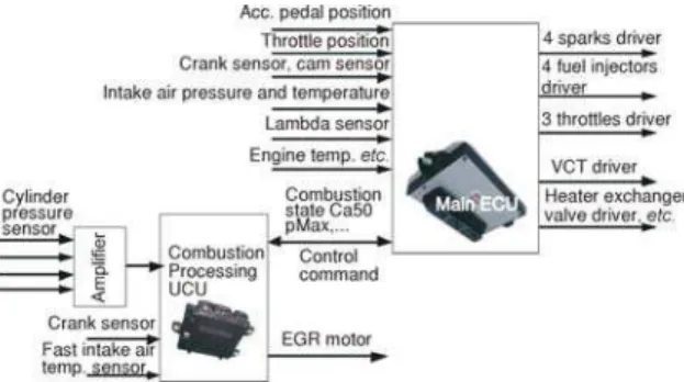
The control system for research en-gine is based on prototype ECU. There are two prototype ECU for the demo en-gine, which are shown in fig. 2. One 128 pin Mototron ECU is used for main con-trol ECU, which will concon-trol injection, ignition, throttle, etc. Another 112 pin Mototron ECU is used as cylinder pres-sure processing ECU. It processes cylin-der pressure signals and sends combus-tion state informacombus-tion to main control ECU.
EGR rate is defined as the mass fraction of exhaust gas in intake air charge, and is cal-culated with the following equation:
EGRrate= -a c
b c100% (1)
where,ais the O2mass fraction of intake charge,b– the O2mass fraction of exhaust gas, and c– the O2mass fraction of air.
In this study, coefficient of variation (COV) of combustion parameter is defined in equation:
COV( )x %
x
=s100 (2)
where,sis standard deviation, andxis the mean value.
Results and discussion
Effects of intake air temperature
The mixture of hydrocarbon fuel and air start incomplete low temperature chemical re-action above 800 K and release some energy, which is called cold flame rere-action. Low
tempera-Figure 1. Schematic diagram of experimental apparatus
ture combustion process generates some active atomic group, which can promote fast exothermic reaction for mixture in next process [9]. As low temperature chemical reaction starts, cylinder pressure and mixture temperature increase. If mixture temperature reaches about 1000 K, fast exo-thermic reaction starts, which is confirmed by literature [10]. It releases nearly all chemical en-ergy, which is called hot flame reaction. The main content of gasoline is hydrocarbon, so the reac-tion mechanism of gasoline is same as hydrocarbon fuel.
Intake air temperature has great influence on HCCI engine combustion. Gasoline is easy to be ignited by spark, but it is hard to be ignited by compression. Study shows that gasoline could be ignited in ambient temperature when engine compression ratio reaches 22 [11]. But compression ratio of conventional gasoline engine is around 10. In the study, the compression ratio has been increased to 13 through piston geometry change. However, the approach of com-pression ratio increasing is still not enough for gasoline auto ignition in ambient intake air tem-perature. So intake air should be heated to suitable temtem-perature. Meanwhile cylinder charge could be reduced due to low intake air density, which is a significant influencing factor for en-gine load expansion. The influence of intake air temperature on HCCI combustion should be in-vestigated and analyzed.
Figure 3 shows the combustion characteristics of HCCI with different intake air perature. As intake air temperature increases, mixture temperature reaches the auto ignition tem-perature early, and combustion phase is advanced, but peak heat release rate (HRR) remains nearly same. HCCI combustion phase is close to TDC, peak pressure increases and peak pres-sure phase is advanced owing to early heat release. Gas temperature in cylinder increases and is advanced, but maximum gas temperature in cylinder does not change so much owing to nearly same total heat release.
Figure 4 shows combustion phase in differ-ent intake air temperature. It can be seen that CA10 and CA50 becomes early with the in-creasing intake temperature. The main reason for this is that exothermic reaction advances and gas temperature rises fast, which will also accel-erate exothermic reaction and shorten combus-tion duracombus-tion.
Figure 5 shows indicated mean effective pressure (IMEP) and COV of IMEP in different intake air temperature. IMEP is mainly affected
by peak pressure and combustion phase. As intake air temperature increases, combustion phase advances and becomes close to TDC. The peak pressure rises slightly, but IMEP decreases with the increasing intake air temperature. The reason is that combustion phase has domain effect on IMEP. Early CA10 leads to low IMEP. Higher intake air temperature shortens combustion dura-tion, meanwhile the influence of cycle variations on combustion phase increases. So COV of IMEP increases as intake air temperature increases.
Figure 6 shows HCCI emission characteristics with different intake air temperature. It can be seen that HC and CO emissions decrease as intake air temperature increases. HC emis-sion mainly comes from temperature boundary layer near cylinder wall. As intake air tempera-ture increases, gas temperatempera-ture in cylinder increases simultaneously. The temperatempera-ture boundary layer becomes thin, which leads few unburned
HC. Meanwhile the increasing gas temperature accelerates HC oxidation reaction, which also reduces HC emission. Higher gas temperature accelerates CO oxidation reaction, which pro-motes the conversion reaction from CO to CO2. The main factors for NOxgeneration process are high gas temperature, rich oxygen content and retention time of nitrogen in hot zone with oxy-gen. As intake air temperature increases, com-bustion timing advances, hot zone area in cylin-der is enlarged and retention time of nitrogen in hot zone with oxygen becomes longer. There-fore NOxemission increases with the increasing intake air temperature.
Effects of exhaust gas re-circulation
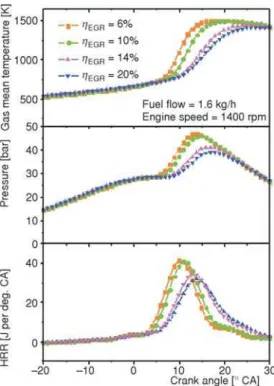
EGR is a common method for controlling HCCI combustion timing. Figure 7 shows HCCI combustion characteristics with different EGR rate. It can be seen that EGR retards com-bustion phase, which leads to low peak pressure and low maximum pressure rising rate (MPRR). Similar results are also conducted from
litera-Figure 5. Effect ofTinon IMEP
Figure 6. Effect ofTinon emissions
ture [12]. The heat specific capacity of exhaust gas is higher than air, which leads high heat spe-cific capacity for mixture with the increasing EGR rate. Gas temperature rises slower due to higher content of exhaust in mixture. The temperature at the end of compression also decreases, which postpones combustion timing. Meanwhile exhaust gas has dilution effect on mixture, which suppresses exothermic reaction and heat release process. As EGR rate increases, maxi-mum pressure rising rate (MPRR) decreases, which contributes low knock intensity. From liter-ature, MPRR is a simple indication parameter to evaluate engine running roughness. The engine is considered too noisy by operator when MPRR exceeds 5 bar per degree [13]. EGR could be employed for decreasing knock tendency in high load operation.
Figure 8 shows HCCI combustion phasing and duration with different EGR rate. Mix-ture combustion timing is determined by fuel chemical reaction process. For gasoline with high octane number, main factors affecting reaction rate are gas temperature and oxygen concentration. As EGR rate increases, mixture heat specific capacity increases, which leads to low gas tempera-ture. Meanwhile oxygen concentration decreases, so the oxidation reaction is suppressed. With the reasons above, CA10 and CA50 are delayed by high EGR rate. When EGR rate increases from 6% to 20%, combustion duration is prolonged from 45° CA to 51° CA.
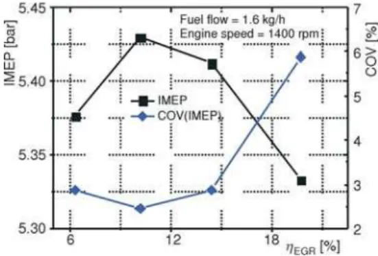
Figure 9 shows the influence of EGR rate on IMEP and COV of IMEP. When EGR rate increases from 6% to 10%, IMEP increases from 5.37 bar to 5.43 bar simultaneously and COV of IMEP decreases from 2.87% to 2.44%. When EGR rate increases to 14%, IMEP de-creases to 5.41 bar and COV of IMEP inde-creases to 2.87%. The results show that relative low EGR rate can promote combustion by retarding combustion timing to a suitable phase. If com-bustion timing goes to suitable position, IMEP increases and COV of IMEP decreases. The en-gine combustion stability can be improved in relative low EGR rate. When EGR rate goes to a higher level, oxygen concentration decreases. In this situation the suppression effect of exhaust gas plays domain effect, which retards combustion timing and decreasing IMEP. As EGR rate increases, the distribution of exhaust gas in cylinder becomes inhomogeneous. Therefore COV of IMEP increases in high EGR rate. When EGR rate increases up to 20%, IMEP decreases to 5.33 bar. COV of IMEP increases to 5.88%, which shows that combustion timing is retarded to a late position and combustion stability becomes worse.
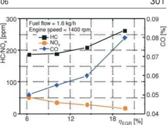
Figure 10 shows emissions characteristics with different EGR rates. It can be seen that CO and HC increase significantly with the increasing EGR rate. CO is generated in low temper-ature combustion reaction phase as an intermediate product of combustion, and it is burned nearly complete in high temperature combustion phase. CO emission is low in high temperature
and high oxygen concentration condition. As EGR rate increases, gas temperature and oxygen concentration decreases. The two factors sup-press CO oxidization equation, which leads CO emission to increase. As EGR rate increases, gas temperature decreases, which leads temperature boundary layer near cylinder wall to become thicker and trap more HC in boundary layer. On the other effect, as gas temperature decreases, un-burned HC increases due to suppression of HC oxidization reaction.
Compared to normal spark-ignition en-gine, NOxemission level of HCCI engine is much
lower. It can be seen that NOxemission decreases as EGR rate increases. Then reason is that, with the increasing EGR rate, gas temperature and oxygen concentration decrease, which sup-press NOxgeneration reaction.
Effects of intake air pressure
Intake air boost technology is an effective method to promote engine power density. In naturally aspirated engine, IMEP in HCCI combustion has load limit, which is around 5 bar in test engine. In this study, the influence of intake air pressure on HCCI combustion characteris-tics is investigated. The independent boost air equipment in test laboratory is used for engine test. As intake air pressure increases, the cylinder filling also increases. In the experiment, there are two test groups for air boost experiment. In one test group, fuel flow is kept around 1.52 kg/h, lambda increases as intake air pressure increases. In the other test group, lambda is kept near 2.45, fuel injection quantity increases as intake air pressure increases. The other engine running conditions are same. Engine speed is 1600 rpm. Intake air temperature is kept around 180 °C and coolant temperature is kept around 90 °C.
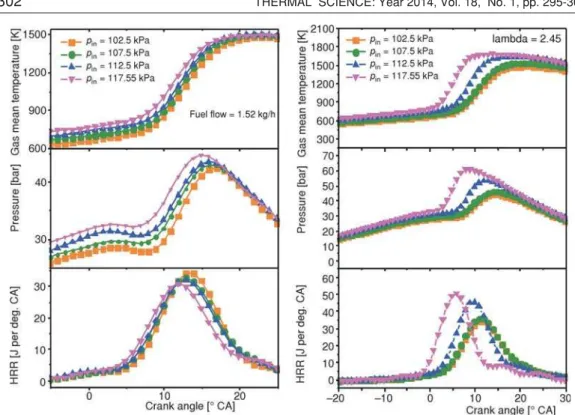
Figure 11 shows the influence of intake air pressure on gas temperature, pressure and HRR. In constant fuel flow test condition, as intake air pressure increases, gas temperature in-creases, and peak temperature timing remains nearly same. Mixture pressure increases and peak pressure timing is advanced. But peak HRR decreases a little. In constant air fuel ratio condition, as intake air pressure increases, gas temperature and pressure increases simultaneously. Peak temperature timing and peak pressure timing are advanced significantly, which leads combus-tion timing to be advanced. Peak HRR also increases significantly.
For gasoline engine, gas temperature and pressure in cylinder are mainly determined by heat release, combustion timing and cylinder mixture filling. Before exothermic reaction, gas temperature and pressure increased by compression. As intake air pressure increases, gas tem-perature and pressure increase in compression process, which advances combustion timing. Cylinder pressure and peak gas temperature increases and becomes early. This is the main influ-ence of intake air boost on HCCI combustion. In the same fuel flow condition, air fuel ratio in-creases as intake air pressure inin-creases, which have two effects on combustion process. High air fuel ratio can suppress combustion due to dilution effect, which leads peak HRR decreasing. In the same air fuel ratio condition, fuel flow increases as intake air pressure increases. HRR in-creases significantly, which leads gas temperature rising and combustion timing becoming early.
Figure 12 shows the influence on intake air pressure on combustion phase. In the same fuel flow condition, as intake air pressure increases, CA10 is advanced and CA50 is nearly same. Combustion duration is prolonged. As intake air pressure increases, cylinder pressure and gas temperature increases simultaneously. Exothermic reaction is advanced, which contributes to early CA10. But high air fuel ratio could suppress fuel reaction with oxygen, which prolongs combustion duration. In the same air fuel ratio condition, there is no suppression effect on fuel exothermic reaction, so CA50 becomes early with air boost. HRR increases as fuel quantity in-creases. This promotes combustion exothermic reaction, which leads combustion duration de-creasing further.
Figure 13 shows the influence of intake air pressure on IMEP and COV of IMEP. In the same fuel flow condition, as intake air pressure increases, IMEP decreases slightly due to combustion duration increasing. Meanwhile COV of IMEP increases due to suppression effect of excessive air. In the same air fuel ratio condition, as intake air pressure increases, injection fuel quantity increases significantly which leads IMEP to increase. With increasing gas temper-ature, combustion reaction is promoted, so COV of IMEP decreases.
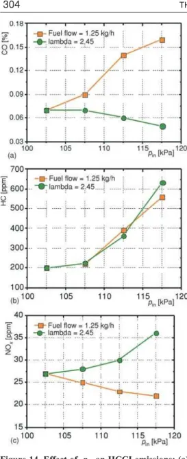
Figure 14 shows the influence of intake air pressure on HCCI emission. In the same fuel flow condition, CO emission increases as intake air pressure increases. The reason is that high oxygen concentration promotes the reaction process from aldehyde group in fuel to CO [14]. In combustion process, CO oxidization reaction is suppressed due to low gas temperature, which leads CO emission increasing. In the same air fuel ratio condition, oxygen concentration remains same. In combustion process, CO oxidization reaction is promoted due to high gas tem-perature, which leads the decreasing of CO emission.
In the two test conditions, HC emission in-creases as intake air pressure inin-creases. HC emis-sion mainly comes from temperature boundary layer near cylinder wall. In the same fuel flow condition, as intake air pressure increases, boundary layer thickness increases with exces-sive air, which leads HC emission increasing. In the same air fuel ratio condition, unburned HC in boundary layer increases as injection fuel quan-tity increases, so HC emission increases.
In the two test conditions, NOx emissions show different tendency as intake air pressure in-creases. In the same fuel flow condition, mixture becomes more homogenous and lean as intake air pressure increases. This leads NOxemission to decrease slightly. In the same air fuel ratio condition, as intake air pressure increases, gas tem-perature increases significantly which results in the increase of NOxemission.
HCCI load expansion
Intake air temperature is different on different operation points. Figure 15 shows the optimal intake air temperature for HCCI combustion without EGR and air boost on different op-erating points. The optimal intake air temperature is lowest in low engine speed and high IMEP Figure 12. Effect of pin on HCCI combustion
phase and duration; (a) CA10, (b) CA50, (c) combustion duration
area. The reason is that combustion speed is low at low engine speed, and gas temperature can increase fast in high load due to more fuel injec-tion quantity. As engine speed increases, the combustion speed should be high due to short timing window, which needs high intake air temperature. In high engine speed condition, exhaust flow is high and the heater exchanger capability increases simultaneously, which con-tributes hot intake air heated by exhaust gas. The OKP system design can reach a wide intake air temperature range from ambient temperature to about 220 °C. Engine HCCI combustion area can reach a relative wide IMEP area with intake temperature control by heat management sys-tem than normal CAI engine.
The range of operating conditions in HCCI mode is usually constrained to a relative small region, as shown in the literature [15, 16]. The upper boundary of HCCI operating area is due
to intolerable combustion roughness and knock, while lower boundary of HCCI operating area is due to increased cycle-to-cycle variation and misfires [17]. In engine high load area, due to high maximum pressure rising rate (MPRR), the knock tendency and combustion noise increase significantly. The combination of EGR and air boost can reduce pressure rising rate and sup-press knock tendency.
Figure 16 shows HCCI load expansion strategy with EGR and air boost. In low speed area, EGR and air boost increase intake air temperature and improve combustion stability. In high load area, EGR and air boost suppress combustion reaction speed and retard combustion Figure 14. Effect of pinon HCCI emissions; (a)
CO, (b) HC, (c) NOx
timing. The maximum IMEP increases from 510 kPa to 720 kPa, which shows a big potential for load expansion with EGR and air boost.
Conclusions
In this study, HCCI combustion and emis-sion characteristics are investigated. Different intake air temperature, EGR rate and intake air pressure are investigated in the experiment. The conclusions of this study are as folow.
· Intake air temperature has domain effect on
HCCI combustion. As intake air
temperature increase, combustion timing is advanced and knock tendency is enhanced. HC and CO emissions decrease, but NOx
emission increases. As intake air temperature increases, engine IMEP decreases and COV of IMEP increases.
External exhaust gas recirculation can decrease gas temperature and prolong combustion duration. Appropriate EGR rate around 10% promotes combustion process and combustion stability, it improves IMEP and COV of IMEP. EGR reduces knock tendency and can be applied for HCCI load expansion.
· There are two test groups designed for intake air pressure investigation. In the same fuel flow condition, as intake air pressure increases, combustion timing is advanced and combustion duration is prolonged. Knock tendency can be suppressed by high air fuel ratio. In the same air fuel ratio condition, as intake air pressure increases, injection quantity increases and combustion process is promoted significantly.
· Intake air temperature should be tuned by heat management system for different operating area. The optimal intake air temperature is low in low engine speed and high load area. The intake air temperature should be high in high engine speed and low load area. Intake air temperature can be adjusted for different operating points from ambient temperature to 220 °C. · EGR and air boost are two effective methods for HCCI combustion control. The combination of EGR and air boost can maximum pressure rising rate and suppress knock tendency. The maximum IMEP increases from 510 kPa to 720 kPa with EGR and air boost. It needs to be designed and calibrated in different operating points for HCCI engine load expansion.
Acknowledgment
The authors would like to thank Science and Technology Commission of Shanghai Municipality (Project No. 09DJ140030), Shanghai Jiao Tong University and Shanghai Auto-motive Industry Corporation (SAIC) for financial and technical support to this study.
Figure 16. HCCI engine load expansion strategy with EGR and air boost
Nomenclature
hEGR – exhaust gas recirculation rate, [%] Tin – intake air temperature, [°C] pin – intake air pressure, [kPa]
Acronyms
CAI – controlled auto ignition
CA10 – crank angle when 10 percent of total heat
– released
CA50 – crank angle when 50 percent of total heat
– released
Reference
[1] Yang, J.,et al., Development of a Gasoline Engine System Using HCCI Technology – The Concept and the Test Results, SAE International 2002-01-2832, 2002
[2] Zhao, H.,et al., Performance and Analysis of a 4-Stroke Multi-Cylinder Gasoline Engine with CAI Com-bustion, SAE International 2002-01-0420, 2002
[3] Zhang, Y.,et al., 2-Stroke CAI Operation on a Poppet Valve DI Engine Fuelled with Gasoline and its Blends with Ethanol, SAE International 2013-01-1674, 2013
[4] Christensen, M.,et al., Demonstrating the Multi Fuel Capability of a Homogeneous Charge Compression Ignition Engine with Variable Compression Ratio, SAE International 1999-01-3679, 1999
[5] Hou, Y. C.,et al., Effect of High-Octane Oxygenated Fuels on n-Heptane-Fueled HCCI Combustion, En-ergy and Fuels, 20(2006), 4, pp. 1425-1433
[6] Dong, H. A. N.,et al., Premixed Ignition Characteristics of Blends of Gasoline and Diesel-Like Fuels on a Rapid Compression Machine,Thermal Science, 17(2013), 1, pp. 1-10
[7] Ma, J. J.,et al., An Experimental Study of HCCI-DI Combustion and Emissions in a Diesel Engine with Dual Fuel, International Journal of Thermal Sciences, 47(2008), 9, pp. 1235-1242
[8] Yang, J., Kenney, T., Robustness and Performance near the Boundary of HCCI Operating Regime of a Single-Cylinder OKP Engine, SAE International 2006-01-1082, 2006
[9] Hernandez, J. J.,et al., Reduction of Kinetic Mechanisms for Fuel Oxidation through Genetic Algorithms, Mathematical and Computer Modelling, 52(2010), 7-8, pp. 1185-1193
[10] Lee, K.,et al., Development of a Reduced Chemical Kinetic Mechanism for a Gasoline Surrogate for Gas-oline HCCI Combustion,Combustion Theory and Modelling, 15(2011), 1, pp. 107-124
[11] Olsson, J.-O.,et al., Compression Ratio Influence on Maximum Load of a Natural Gas Fueled HCCI En-gine, SAE technical paper 2002-01-0111, 2002
[12] Swami Nathan, S.,et al., Effects of Charge Temperature and Exhaust Gas Re-Circulation on Combustion and Emission Characteristics of an Acetylene Fuelled HCCI Engine,Fuel, 89(2009), 2, pp. 515-521 [13] Kalghatgi, G. T., Head, R. A., Combustion Limits and Efficiency in a Homogeneous Charge Compression
Ignition Engine,International Journal of Engine Research, 7(2006), 3, pp. 215-236
[14] Kwon, O. S., Lim, O. T. Effect of Boost Pressure on Thermal Stratification in HCCI Engine Using the Multi-Zone Model,Journal of Mechanical Science and Technology, 24(2010), 1, pp. 399-406
[15] Olsson, J.-O.,et al., A Turbo Charged Dual Fuel HCCI Engine, SAE International 2001-01-1896, 2001 [16] Fuerhapter, A.,et al., CSI – Controlled Auto Ignition – the Best Solution for the Fuel Consumption –
Ver-sus Emission Trade-Off?, SAE technical paper 2003-01-0754, 2003
[17] Yang, J., Expanding the Operating Range of Homogeneous Charge Compression Ignition-Spark-Ignition Dual-Mode Engines in the Homogeneous Charge Compression Ignition Mode,International Journal of Engine Research, 6(2005), 4, pp. 279-288
Paper submitted: April 16, 2013 Paper revised: January 15, 2014 Paper accepted: January 17, 2014
ECU – engine control unit EGR – exhaust gas recirculation HCCI – homogenous charge compression
– ignition
IMEP – indicated mean effective pressure
MPRR – maximum pressure rising rate PFI – port fuel injection
ROHR – rate of heat release TDC – top dead center