UNIVERSIDADE DA BEIRA INTERIOR
Engenharia
Effect of corrosive solutions on composites
laminates subjected to low velocity impact
loading
Nurdane Mortas
Dissertação para obtenção do Grau de Mestre em
Engenharia Electromecânica
(2º ciclo de estudos)
Orientador: Prof. Doutor Paulo Nobre Balbis dos Reis
ii To my father.
iii
ACKNOWLEDGMENTS
I would like to thank my advisor, Professor Paulo Nobre Balbis dos Reis, for his encouragement, guidance and support over the present academic year.
My sincere thanks go to Professor Mário Santos, from the DEEC/UC, and Eng. Carlos Coelho, from the ESTA/IPT, by the help given in terms of damage analysis and impact tests, respectively.
My sincere thanks go to Professor Orhan Er and Professor Mustafa Yaz by the opportunity to perform new challenges in my academic way.
To Electromechanical Department of the University of Beira Interior thank you for giving me all facilities.
I would like to thank my colleagues, Patricia Silva and Paulo Santos; by the friendship and help.
I am deeply and forever indebted to my family for their love, support and encouragement throughout my entire life.
iv
Resumo
Nos últimos anos temos assistido a um aumento significativo da utilização de materiais compósitos reforçados com fibras nos mais variados campos da engenharia e este fenómeno tende a continuar. Neste contexto, as estruturas em materiais compósitos podem ser expostas a uma enorme variedade de ambientes corrosivos provocando, deste modo, a degradação das suas propriedades mecânicas. Na verdade podem ser encontrados na literatura alguns trabalhos, mas os estudos apresentados não se revelam suficientes para estabelecer um conhecimento aprofundado nesta temática. Então, este trabalho visa estudar a resposta ao impacto de baixo velocidade de laminados Kevlar/epóxi e laminados carbono/epóxi após imersão em ácido clorídrico (HCl) e hidróxido de sódio (NaOH). As soluções agressivas mostraram afetar significativamente a resistência ao impacto, mas o seu efeito é fortemente dependente da concentração da solução. Por outro lado, a temperatura também apresenta um efeito significativo, independentemente da solução agressiva, no desempenho ao impacto dos referidos laminados e na sua resistência residual à flexão.
Palavras-chave
Soluções Corrosivas; Resistência ao Impacto; Propriedades Mecânicas; Compósitos de Matriz Polimérica (PMCs).
v
Abstract
In recent years, there has been a rapid growth in the use of fibre reinforced composite materials in engineering applications and this phenomenon will be continuing. In this context, composite structures can be exposed to a range of corrosive environments during their in-service life, which causes degradation in terms of material properties. Some works can be found in open literature, but the studies presented are not sufficient to establish a full knowledge about this subject. Therefore, the aim of this work is study the low velocity impact response of Kevlar/epoxy laminates and carbon/epoxy laminates, after immersion into hydrochloric acid (HCl) and sodium hydroxide (NaOH). The aggressive solutions affect significantly the impact strength, but their effects are strongly dependent of the concentration. On the other hand, a significant effect of the temperature can be found, independently of the aggressive solution, on the impact performance and residual bending strength.
Keywords
Corrosive solutions; Impact Strength; Mechanical Properties; Polymer-matrix composites (PMCs).
vi
CONTENTS
Introduction 1 1 – Literature Review 2 1.1 – Composite Materials 2 1.1.1 – Introduction 21.1.2 – Classification of the Composite Materials 5
1.1.3 – Fibers 6
1.1.4 – Matrix 11
1.2 - Impact Performance of Composite Materials 18
1.2.1 – Introduction 18
1.2.2 – Impact Classification 18
1.2.3 – Damages Promoted by Impact Loads 19
1.2.4 – Residual Strength After Impact Loads 21 1.2.5 – Effect of the Hostile Environments on the Impact Strength 23
2 – Material, Equipment and Procedure 26
2.1 – Introduction 26
2.2 – Manufacturing Process of the Laminates 26
2.3 – Specimens 26
2.4 – Equipment 27
2.5 – Experimental Procedure 27
3 – Results and discussion 29
4 – Conclusions and Future work 38
5.1 – Conclusions 38
5.2 – Future wok 39
vii
List of Figures
Figure 1.1 – The evolution of engineering materials 3 Figure 1.2 – A classification scheme for the various composite types 6
Figure 1.3 – Moleculer structure of Kevlar 49 8
Figure 1.4 – Principal ingredients for an epoxy matrix: (a) A molecule of diglycidyl ether of bsphenol A (DGEBA) epoxy resin; (b) A molecule of diethylene triamine (DETA) curing agent
13
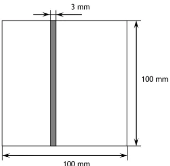
Figure 1.5 – Initial damage in an impacted 0/90/0 composite plate 20 Figure 1.6 – Characteristic residual strength versus impact energy curve 22 Figure 2.1 – Geometry of the specimens used in the impact tests 27
Figure 2.2 – Impact machine IMATEK-IM10 28
Figure 3.1 – Typical diagrams load versus time obtained, at room temperature, for: a) Kevlar/epoxy laminates; b) Carbon/epoxy laminates.
29 Figure 3.2 – Typical diagrams load versus displacement obtained, at room temperature,
for: a) Kevlar/epoxy laminates; b) Carbon/epoxy laminates.
30 Figure 3.3 – Elastic recuperation, for the different laminates, as a function of the corrosive
solution and respective concentration.
32 Figure 3.4 – Typical images of the damages for: a) Carbon laminates (control samples);
b) Kevlar laminates (control samples); c) Carbon laminates immersed into 15% NaOH; d) kevlar laminates immersed into 15% NaOH; e) Carbon laminates immersed into 35% NaOH; f) Kevlar laminates immersed into 35% NaOH; g) Carbon laminates immersed into 15% HCl; h) Kevlar laminates immersed into 15% HCl.
33
Figure 3.5 – Residual bending strength for laminates subjected to different solutions and concentrations.
34 Figure 3.6 – Young’s modulus of the resin after exposition at different solutions and
concentrations.
35 Figure 3.7 – Elastic recuperation, for the different laminates and solutions, as a function
of the temperature.
36 Figure 3.8 – Residual bending strength for laminates subjected to different solutions and
temperature.
viii
List of Tables
Table 1.1 – Properties of typical reinforcements. 9
Table 1.2 – Properties of selected natural fibers. 10 Table 1.3 – Maximum continuous use temperatures for different polymeric resins. 12 Table 1.4 – Typical Properties of Cast Epoxy Resin (at 23 ºC. 13 Table 2.1 – Summary of all test conditions studied. 28 Table 3.1 – Effect of corrosive solutions on the impact parameters. 31 Table 3.2 – Effect of temperature for the different solutions on the impact parameters. 36
ix
List of Acronyms
BMI Bismaleimide CVD DETA DFAChemical vapor deposition Diethylene triamine Design for assembly DFM Design for manufacturing DGEBA Diglycidyl ether of bisphenol A FRP GRP Fiber-reinforced plastics Glass-reinforced plastics HCl Hydrochloric acid H2SO4 Sulphuric acid LARC LEO
Langley Research Center thermoplastic imide Low earth orbit
NaOH Sodium hydroxide PAI
PAN
Polyamide imide Polyacrylonitrile PEEK Polyetheretherketone PEI Polyether imide PET PMC PMR PP PPS Thermoplastic Polyesters Polymeric matrix composites
Polymerisation of monomer reactant Polypropylene Polyphenylene Sulfide RRIM RTM SMC SRIM
Reinforced reaction injection molding Resin transfer molding
Sheet molding compound
x
Nomenclature
Ef Flexural modulus L Unsupported length t Specimen thickness w WidthTg Glass transition temperature
Compressive strain1
Introduction
In recent years, there has been a rapid growth in the use of fiber reinforced composite materials in engineering applications and there is a clear indication that this will be continuing. In this context, it is becoming common the components manufactured by composite materials for applications at highly corrosive environments, as an alternative to the stainless or coated steels. However, the studies presented on the open literature are not sufficient to establish a full knowledge about the effect of hostile solutions on the PMC mechanical properties.
On the other hand, it is well known that the composites are very strong in the plane, but with very low impact performance through the thickness. Various types of damages can occur, which are very dangerous because they are not easily detected visually and they can affect significantly the residual properties and structural integrity of those materials.
Therefore, the aim of this work is study the low velocity impact response of Kevlar/epoxy laminates and carbon/epoxy laminates, after immersion into hydrochloric acid (HCl) and sodium hydroxide (NaOH). The effect of concentration and temperature of the solutions on the impact strength will be analyzed and the residual bending strength will be compared with the control samples. Composites reinforced by carbon or Kevlar fibers have several application fields, but the open literature does not report any study about the effect of corrosive environments on their impact strength.
For this purpose, the present thesis is composed by 4 chapters. Chapter 1 intends to introduce the composite materials, where the mechanical properties are discussed in terms of their constituents, and the impact strength of those materials. The impact will be classified from the perspective of various authors and an introduction to different damage mechanisms will be done. Chapter 2 describes the material, in terms of constituents and manufacturing process, the equipment and the experimental procedure used along the present work. Along the chapter 3 will be presented the results and respective discussion. Finally, chapter 4 presents the main conclusions of this work and some suggestions for future works.
2
Chapter 1
Literature Review
This chapter intends to introduce the subject studied on this work. An introduction to the composite materials will be done, where the mechanical properties are discussed in terms of their constituents. Subsequently, the impact strength of the composite materials will be presented. The impact will be classified from the perspective of various authors as well as an introduction to different damage mechanisms. In this case, the main focus will be given to impact damage occurring at low velocity. Finally, it will be introduced the topic about corrosive environments and their effects on the mechanical properties of the composite materials.
1.1 - Composite Materials
1.1.1 – Introduction
A composite, in general, is defined as a combination of two or more components differing in form or composition on a macroscale, with two or more distinct phases having recognisable interfaces between them. Proper combination of materials into composites gives rise to properties which transcend those of the constituents, as a result of the principle of combined action. Composite materials have been utilized to solve technological problems for a long time but only in the 1960s did these materials start capturing the attention of industries with the introduction of polymeric-based composites (see figure 1.1). The reinforcements can be fibers, particulates, whiskers and the matrix materials can be metals, plastics or ceramics. These materials, depending on their major characteristics (e.g., stiffness, strength, density and melting temperature), can be broadly divided into four main categories: metals, plastics, ceramics and composites. In fact, composite materials have become common engineering materials and are designed and manufactured for various applications including automotive components, sporting equipments, aerospace parts, consumer products and in marine or oil industries [1].
The concept of composites was not invented by human beings; it is found in nature [2]. Historically, the importance of manufacturing in the development of civilization is usually underestimated. The earliest humans had access to only a very limited number of materials, those that occur naturally: stone, wood, clay, skins, and so on. With time they discovered techniques for producing materials that had properties superior to those of the natural ones; these new materials included pottery and various metals [3]. The shell of invertebrates, such as snails and oysters, is an example of a composite. Such shells are stronger and tougher than
3 man-made advanced composites. Scientists have found that the fibers taken from a spider’s web are stronger than synthetic fibers [1]. The ancient Israelite workers during their tenure under the Pharaohs incorporated chopped straw in bricks as a means of enhancing their structural integrity. In the Mongolian arcs, the compressed parts are made of corn and the stretched parts are made of wood and cow tendons glued together [4]. The Japanese Samurai warriors were known to use laminated metals in the forging of their swords to obtain desirable material properties [5].
Figure 1.1 - The evolution of engineering materials [6].
In terms of comparasion with the traditional engineering materials, composites present several advantages [1, 2]:
They are very strong and stiff, yet light in weight, giving them strength-to-weight and stiffness-to-weight ratios several times greater than steel or aluminum;
Fatigue properties are generally better than for the common engineering metals. Thoughness is often greater, too.
High corrosion resistance;
It is possible to achieve combinations of properties not available with metals, ceramics or polymers alone.
Complex parts, appearance and special contours can be obtained by composite materials;
4 The cost of tooling required for composites processing is much lower than that for metals processing as consequence of the lower pressure and temperature required; Composite materials offer greater feasibility for employing design for
manufacturing (DFM) and design for assembly (DFA) techniques. On other hand, some disadvantages can be found [1, 2]:
The materials cost for composite materials is very high compared to that of steel and aluminum;
Properties of many important composites are anisotropic, which means the properties differ depending on the direction in which they are measured;
The temperature resistance dependents of the matrix used;
Solvent resistance, chemical resistance, and environmental stress cracking of composites depend on the properties of polymers. Some polymers have low resistance to solvents and environmental stress cracking;
Composites absorb moisture, which affects their properties and dimensional stability;
Nowadays, it is difficult to find any industry that does not utilize the benefits of composite materials. The aerospace industry was the first one to apply the benefits of composite materials. Airplanes, rockets and missiles can fly higher, faster and farther with the help of composites [1]. In 1999, for example, the aerospace industry consumed 23 million pounds in composite materials. Typical mass reductions achieved are around 20 to 35%. The mass saving in fight planes increases the payload capacity and the missile performance. On the other hand, in low Earth orbit (LEO), where temperature variation is from –100 to +100°C, it is important to maintain dimensional stability in support structures as well as in reflecting members. Carbon epoxy composite laminates can be designed to give a zero coefficient of thermal expansion. Typical space structures are tubular truss structures, antenna reflectors, etc. In space shuttle composite materials provide weight savings of 2688 lb per vehicle [1].
Sports and recreation equipment suppliers are becoming major users of composite materials. The growth in structural composite usage has been greatest in high-performance sporting goods and racing boats. Anyone who has visited a sporting goods store can see products such as golf shafts, tennis rackets, snow skis, fishing rods, etc., made of composite materials. These products are light in weight and provide higher performance, which helps the user in easy handling and increased comfort [1].
Composite materials are used in a variety of marine applications such as passenger ferries, power boats, buoys, etc., because of their corrosion resistance and light weight, which gets translated into fuel efficiency, higher cruising speed and portability. The majority of components are made of glass-reinforced plastics (GRP) and about 70% of all recreational
5 boats are made by composite materials. They are also used in offshore pipelines for oil and gas extractions. The motivation for their use in such applications includes reduced handling and installation costs as well as better corrosion resistance and mechanical performance. Another benefit comes from the use of adhesive bonding, which minimizes the need for a hot work permit if welding is employed [1].
The construction and civil structure industries are the second major users of composite materials. The use of glass and carbon-reinforced plastics for bridges manufacturing, and/or their repairing, improves the corrosion and durability [1]. Composite materials are used also for a wide variety of consumer products, such as sewing machines, doors, bathtubs, tables, chairs, computers, printers, etc. The majority of these components are short fiber composites made by molding technology such as compression molding, injection molding, RTM and SRIM [1].
Biomedical applications encompass those that pertain to the diagnosis and treatment of conditions, diseases and disabilities, as well as the prevention of diseases and conditions. They include implants (e.g., hips, heart valves, skin and teeth), surgical and diagnostic devices, pacemakers (devices connected by electrical leads to the wall of the heart, enabling electrical control over the heartbeat), electrodes for collecting or sending electrical or optical signals for diagnosis or treatment, wheelchairs, devices for helping the disabled, exercise equipment, pharmaceutical packaging (for controlled release of the drug into the body, or for other purposes) and instrumentation for diagnosis and chemical analysis (such as equipment for analyzing blood and urine). Implants are particularly challenging, as they need to be made of materials that are biocompatible (compatible with fluids such as blood), corrosion resistant, wear resistant, fatigue resistant and that are able to maintain these properties over tens of years [7].
1.1.2 – Classification of the Composite Materials
One typical classification of the composite materials can be shown in figure 1.2, which consists of three main divisions: particle-reinforced, fiber-reinforced, and structural composites. At least, two subdivisions exist for each main category [3]. According with Vimnson [5] the configurations are:
Discontinuous fiber reinforced composite – Consists of chopped fibers or whiskers embedded within a matrix;
Fabric reinforced composite – The embedded fiber assembly consists of a fabric, which may be woven, knitted or braided;
Fiber reinforced composite – Consists of embedded continuous/discontinuous fibers in a matrix;
6 Filamentary composite – Material reinforced by continuous fibers embedded in a
matrix;
Unidirectional fiber reinforced composite – The embedded fibers are all aligned in a single direction.
Figure 1.2- A classification scheme for the various composite types [3].
1.1.3 – Fibers
The word fiber means a single, continuous material whose length is at least 200 times its width or diameter and filaments are endless or continuous fibers [8]. Fibers are filaments of reinforcing material, generally circular in cross-section, although alternative shapes are sometimes used (e.g., tubular, rectangular, hexagonal). Diameters range from less than 0.0025 mm to about 0.13 mm, depending on material [2].
There are two different classes of fibers: natural (fibers from mineral, plant and animal sources) and synthetic (man-made fibers). Within these two classes, synthetics are usually more uniform in size, are more economical to use and behave in a more predictable manner. For engineering applications the most commonly employed significant fibers are glass fibers, metallic fibers and organically-derived synthetic fibers. Most strong and stiff fibers (e.g., ceramic fibers of glass, graphite-carbon, boron carbide and silicone carbide) are usually difficult to use as structural materials in bulk. However, embedding such materials in a ductile matrix (such as a polymer or metal) enables them to behave as a stronger, stiffer and tougher material.
Glass fibers are the most common of all reinforcing fibers for polymeric matrix composites (PMC). The principal advantages of glass fibers are low cost, high tensile strength, high chemical resistance and excellent insulating properties [9]. The two types of glass fibers
7 commonly used in the fiber-reinforced plastics (FRP) industry are E-glass and S-glass [2]. Another type, known as C-glass, is used in chemical applications requiring greater corrosion resistance to acids than is provided by E-glass. E-glass has the lowest cost of all commercially available reinforcing fibers, which is the reason for its widespread use in the FRP industry. S-glass, originally developed for aircraft components and missile casings, has the highest tensile strength among all fibers in use. However, the compositional difference and higher manufacturing cost make it more expensive than E-glass [9]. The disadvantages of these fibers are relatively low tensile modulus and high density (among the commercial fibers), sensitivity to abrasion during handling (which frequently decreases its tensile strength), relatively low fatigue resistance and high hardness (which causes excessive wear on molding dies and cutting tools) [1].
Carbon fibers are mainly composed of carbon atoms that are bonded together to form microscopic crystals orientated along the fiber axis. These fibers are extremely fine with a diameter range of 0.005–0.010 mm [2]. Most commercial production of carbon fibers is based on polyacrylonitrile (PAN) technologies. Filaments of polyacrylonitrile or pitch (obtained from residues of the petroleum products) are oxidized at high temperatures (300 0C), then heated further to 1500 0C in a nitrogen atmosphere. High modulus of elasticity is obtained by drawing at high temperature [1]. In PAN-based fibers, the linear chain structure is transformed to a planar structure during oxidative stabilization and subsequent carbonization. Basal planes oriented along the fiber axis are formed during the carbonization stage. In general, it is seen that the higher the tensile strength of the precursor the higher is the tenacity of the carbon fiber. Tensile strength and modulus are significantly improved by carbonization under strain when moderate stabilization is used. On the other hand, the strength of a carbon fiber depends on the type of precursor, the processing conditions, heat treatment temperature and the presence of flaws and defects. Carbon fibers are very brittle because the layers in the fibers are formed by strong covalent bonds [10]. Carbon fibers are commercially available with a variety of tensile modulus values ranging from 207 GPa, on the low side, to 1035 GPa on the high side. In general, the low-modulus fibers have lower density, lower cost, higher tensile and compressive strengths, and higher tensile strains-to-failure than the high-modulus fibers. Among the advantages of carbon fibers are their exceptionally high tensile strength–weight ratios as well as tensile modulus–weight ratios, very low coefficient of linear thermal expansion (which provides dimensional stability), high fatigue strengths and high thermal conductivity. The disadvantages are their low strain-to-failure, low impact resistance and high electrical conductivity [9].
Aramid fibers are highly oriented aromatic polyamides that are heat resistant and very strong. They are a long-chain synthetic polyamide, in which, at least, 85% of the amide linkages (–CO–NH–) are linked directly by two aromatic rings. These aromatic polyamides are obtained by synthesis at -10 0C, fibrillated and drawn to obtain high modulus of elasticity [1].
8 The first aramid fibers were introduced by DuPont (USA) in the early 1960s. These fibers are used in fire-fighting apparel and other items that require heat resistance. On the other hand, they are used in applications that require energy absorption [10]. Aramid fibers are highly crystalline aromatic polyamide fibers that have the lowest density, giving the highest strength-to-weight ratios of all fibers [2]. Kevlar 49 is one aramid fiber available in the market for applications (marine and/or aerospace applications) where lightweight, high tensile strength and resistance to impact damage are required. Like carbon fibers, they present a negative coefficient of thermal expansion along the longitudinal direction. The major disadvantages of aramid fiber-reinforced composites are their low compressive strengths and difficulty in cutting or machining [9]. The molecular structure of aramid fibers, such as Kevlar 49, is illustrated in figure 1.3 [9].
Figure 1.3 - Moleculer structure of Kevlar 49 [9].
Kevlar 49 fibers do not melt or support combustion but will start to carbonize at about 4270C. The maximum long-term use temperature recommended for Kevlar 49 is 160 0C. They have very low thermal conductivity, but a very high vibration damping coefficient. Except for a few strong acids and alkalis, their chemical resistance is good. However, they are quite sensitive to ultraviolet lights. Prolonged direct exposure to sunlight causes discoloration and significant loss in tensile strength. The problem is less pronounced in composite laminates in which the fibers are covered with a matrix. Ultraviolet light-absorbing fillers can be added to the matrix to further reduce the problem [9]. Kevlar 49 fibers are hygroscopic and can absorb up to 6% moisture at 100% relative humidity and 23 0C. The equilibrium moisture content (i.e., maximum moisture absorption) is directly proportional to relative humidity and is attained in 16–36 h. Absorbed moisture seems to have very little effect on the tensile properties of Kevlar 49 fibers. However, at high moisture content, they tend to crack internally at the preexisting microvoids and produce longitudinal splitting.
9
Boron fibers are manufactured by chemical vapor deposition (CVD) of boron onto a heated substrate (either a tungsten wire or a carbon monofilament). Boron vapor is produced by the reaction of boron chloride with hydrogen [9]. Tungsten filament (diameter 12 mm) serves to catalyze the reaction between boron chloride and hydrogen at 1200 0C [2]. Nowaday, commercial boron fibers are produced in diameters of 0.1, 0.142 and 0.203 mm, which are much larger than those of other reinforcing fibers [9]. The most prominent feature of boron fibers is their extremely high tensile modulus, which is in the range of 379–414 GPa. Boron fibers offer excellent resistance to buckling and their principal disadvantage is the cost. Consequently, its use is practically restricted in some aerospace applications [2, 9].
Table 1.1 - Properties of typical reinforcements [1]
Natural fibers, such as cotton, wool and silk, have tenacities in the order of 0.1–0.4 N/tex and initial moduli ranging from 2–5 N/tex. However, fibers such as flax, hemp, jute and ramie may have higher strength and stiffness. The low specific gravity of fibers like jute results in a higher specific strength and stiffness than glass fibers and this may be a benefit, especially in parts designed for bending stiffness. The tensile strength and modulus of jute are lower than glass fibers; however, the specific modulus of the jute fiber is higher. The advantage of jute fibers as a substitute of glass fibers, partly or totaly, in the reinforcement of composite materials arises from its lower specific gravity (1.50) and higher specific modulus (11.46 N/tex) when compared with glass (2.58 and 10.85 N/tex, respectively). Furthermore, the lower cost and the renewable nature of jute, requiring less energy for its
10 production, make it an attractive reinforcing fiber in composites for some engineering applications [10].
Examples of natural fibers are jute, flax, hemp, remi, sisal, coconut fiber (coir) and banana fiber (abaca). All these fibers are grown as agricultural plants in various parts of the world and are commonly used for making ropes, carpet backing, bags and so on. The components of natural fibers are cellulose microfibrils dispersed in an amorphous matrix of lignin and hemicellulose. Depending on the type of the natural fiber, the cellulose content is in the range of 60–80 wt% and the lignin content is in the range of 5–20 wt%. In addition, the moisture content in natural fibers can be up to 20 wt%. The properties of some natural fibers are presented in Table 1.2 [9].
Table 1.2 - Properties of selected natural fibers [9].
Property Hemp Flax Sisal Jute
Density (g/cm3) 1.48 1.4 1.33 1.46
Modulus (GPa) 70 60-80 38 10-30
Tensile strength (MPa) 550-900 800-1500 600-700 400-800
Elongation to failure (%) 1.6 1.2-1.6 2-3 1.8
Nowadays, natural fiber-reinforced polymers have a special interest in the automotive industry (door inner panel, seat back, roof inner panel, etc.) beacuse [9]:
They are environment-friendly (they are biodegradable) and, unlike glass and carbon fibers, the energy necessary to produce them is very small;
The density of natural fibers is around 1.25-1.5 g/cm3 compared with 2.54 g/cm3 for E-glass fibers and 1.8–2.1 g/cm3 for carbon fibers;
The modulus–weight ratio of some natural fibers is greater than observed for E-glass fibers;
Natural fiber composites provide higher acoustic damping than glass or carbon fiber composites (important requirement for automotive applications);
Natural fibers are much less expensive than glass and carbon fibers.
However, there are several limitations for the natural fibers. The tensile strength, for example, is relatively low and present higher moisture absorption. At temperatures higher than 2000C, natural fibers start to degrade, first by the degradation of hemicellulose and then by the degradation of lignin. The degradation leads to odor, discoloration, release of volatiles, and deterioration of mechanical properties [9].
11
1.1.4 – Matrix
A matrix fulfills several functions in a composite structure, most of which are vital to the satisfactory performance of the material. The matrix usually comprises 30%–40% of the composite. Typically, the matrix has a lower density, stiffness and strength than the fibers [5]. The main functions of a matrix in a fiber-reinforced composite are [1]:
The matrix binds the fibers together and transfers the load to the fibers. It provides rigidity and shape to the structure;
The matrix isolates the fibers and, consequently, each individual fiber can work separately. This stops or decreases the crack propagation;
The matrix provides a good surface finish quality and helps the production of net-shape or near-net-net-shape parts;
The matrix provides protection to reinforcing fibers against chemical attack and mechanical damage (wear);
Depending of the matrix selected some mechanical properties can be influenced (compressive strength, ductility, impact strength, interlaminar shear strength). A ductile matrix will increase the toughness of the structure;
The failure mode is strongly affected by the matrix used as well as its compatibility with the fiber.
There are a large variety of matrix systems available where, each ones, presents advantages and disadvantages. Matrix selection is performed based on chemical, thermal, electrical, flammability, environmental, cost, performance and manufacturing requirements. The materials available for matrix can be [4]: polymeric resins (thermoplastic resins and thermoset resins); mineral materials used for high temperatures (silicon carbide, carbon, etc.); metallic materails (aluminum alloys, titanium alloys, etc.). Typically, the matrix has a lower density, stiffness and strength than the fibers. For fibers to carry maximum load, the matrix must have a lower modulus and greater elongation than the reinforcement. The matrix itself should provide enough fracture toughness and ductility performance. The ultimate thermo-mechanical characteristics (heat resistance and thermal properties) of the composites are principally governed by the matrix. On the other hand, the polymeric materials are usually viscoelastic or viscoplastic, which are affected by time, temperature and moisture. Consequently, the matrix determines the service operating temperature of the composites as well as the manufacturing process of those materials. ). Matrix polymers can be thermoset or thermoplastic in nature and they have different behavior in presence of the temperature as shown in Table 1.3 [1]. Thermoset polymers (epoxies, polyesters and vinylesters) are tipicaly used as matrix in composites reinforced by continuous/long fibers as consequence of their low viscosity. On the other hand, thermoplastic polymers are used essentially with short fibers where the composites are obtained by injection molded.
12
Thermoset materials when cured cannot be remelted or reformed. During curing,
they form three-dimensional molecular chains, called cross-linking. As consequence of these cross-linkings, the molecules are not flexible and cannot be remelted or reshaped. Thermoset resins provide easy processability and better fiber impregnation because the liquid resin is used at room temperature for various processes such as filament winding, pultrusion and RTM. These resins offer greater thermal and dimensional stability, better rigidity, higher electrical resistance, chemical resistance and solvent resistance. The most common resin materials are epoxy, polyester, vinylester, phenolics, cyanate esters, bismaleimides and polyimides [1].
Table 1.3 - Maximum continuous use temperatures for different polymeric resins [1].
Materials Maximum Continuous Use Temperature (0C)
Thermosets Vinylester 60-150 Polyester 60-150 Phenolics 70-150 Epoxy 80-215 Cyanata esters 150-250 Bismaleimide 230-320 Thermoplastics Polyethylyene 50-80 Polyproplyene 50-75 Acetal 70-95 Nylon 75-100 Polyester 70-120 PPS 120-220 PEEK 120-250 Teflon 200-260
Epoxy resins are low-molecular-weight organic liquid resins containing a number of epoxide groups, which are three-member rings of one oxygen atom and two carbon atoms [9]. The polymerization (curing) reaction to transform the liquid resin to the solid state is initiated by adding small amounts of a reactive curing agent just before incorporating fibers into the liquid mix. A typical epoxy resin is the diglycidyl ether of bisphenol A (DGEBA), which contains two epoxide groups (one at each end of the molecule), and other typical curing agent is the diethylene triamine. Hydrogen atoms in the amine (NH2) groups of a DETA molecule react with the epoxide groups of DGEBA molecules. As the reaction continues, DGEBA molecules form cross-links with each other and a three-dimensional network structure is slowly formed. The resulting material is a solid epoxy polymer [9].
13 The properties of a cured epoxy resin depend principally on the cross-link density (spacing between successive cross-link sites). In general, the tensile modulus, glass transition temperature and thermal stability, as well as chemical resistance, are improved with increasing cross-link density, but the strain to failure and fracture toughness are reduced. Factors that control the crosslink density are the chemical structure of the starting liquid resin (e.g., number of epoxide groups per molecule and spacing between epoxide groups), functionality of the curing agent (e.g., number of active hydrogen atoms in DETA) and the reaction conditions, such as temperature and time [9]. The continuous use temperature for DGEBA-based epoxies is 1500C or less. Higher heat resistance can be obtained with epoxies based on novolac and cycloaliphatics, for example, which have a continuous use temperature ranging up to 2500C. In general, the heat resistance of an epoxy is improved if it contains more aromatic rings in its basic molecular chain [9].
Figure 1.4 - Principal ingredients for an epoxy matrix: (a) A molecule of diglycidyl ether of bşsphenol A (DGEBA) epoxy resin; (b) A molecule of diethylene triamine (DETA) curing agent [9].
Table 1.4- Typical Properties of Cast Epoxy Resin (at 230C)
Density (g/cm3) 1.2-1.3
Tensile strength, MPa (psi) 55-130 (8.000-19.000) Tensile modulus, GPa (106 psi) 2.75-4.10 (0.4-0.595)
Passions’s ratio 0.2-0.33
Coefficient of thermal expansion, 10-6
m/m per 0C (10-6 in./in. per 0F) 50-80 (28-44)
Cure shrinkage, % 1-5
Epoxy matrix has the following advantages over other thermoset matrices [9]: wide variety of properties; absence of volatile matters during the cure process; low shrinkage during the cure process; excellent resistance to chemicals and solvents; excellent adhesion to
14 a wide variety of fillers, fibers and other substrates. On the other hand, the main disadvantages are its relatively high cost and long cure time. High moisture absorption reduces its glass transition temperature as well as its modulus and other mechanical properties.
Liquid epoxies are used in RTM, filament winding, pultrusion, hand lay-up, and other processes with various reinforcing fibers such as glass, carbon, aramid, boron, etc. Semi-solid epoxies are used in prepreg for vacuum bagging and autoclave processes. Solid epoxy capsules are used for bonding purposes. Epoxies are more costly than polyester and vinylesters and are therefore not used in cost-sensitive markets (e.g., automotive and marine) unless specific performance is needed. Epoxies are generally brittle, but toughened epoxies are made by adding thermoplastics to the epoxy resin by various patented processes [1].
Phenolic resins are used for aircraft interiors, stowbins and galley walls, as well as other commercial markets that require low-cost, flame-resistant, and lowsmoke products. Phenolics are formed by the reaction of phenol (carbolic acid) and formaldehyde, catalyzed by an acid or base. Urea, resorcinol or melamine can be used instead of phenol to obtain different properties. Their cure characteristics are different than other thermosetting resins such as epoxies, due to the fact that water is generated during cure reaction. The water is removed during processing. In the compression molding process, water can be removed by bumping the press. Phenolics are generally dark in color and therefore used for applications in which color does not matter. The phenolic products are usually red, blue, brown or black in color. Phenolics are used for various composite manufacturing processes like: filament winding, RTM, injection molding and compression molding. Phenolics provide easy processability, tight tolerances, reduced machining and high strength. Because of their high temperature resistance, phenolics are used in exhaust components, missile parts, manifold spacers, commutators and disc brakes [1].
Unsaturated polyesters are the most versatile class of thermosetting polymers. They are macromolecules consisting of an unsaturated component (maleic anhydride or its transisomer, fumaric acid; which provides the sites for further reaction) and a saturated dibasic acid or anhydride with dihydric alcohols or oxides (typically phthalic anhydride, which can be replaced by an aliphatic acid, like adipic acid, for improved flexibility). The resin is cured by use of a free radical catalyst, the decomposition rate of which determines the curing time. Hence, curing time can be decreased by increasing the temperature (for a high temperature cure, say at 100 ºC, benzoyl peroxide is commonly used; whereas for a room temperature cure, other peroxides with metal salt accelerators are preferred). Crosslinking reactions occur between the unsaturated polymer and the unsaturated monomer, converting the low viscosity solution into a three-dimensional network system. Crosslink densities can change (by direct proportionality), the modulus, Tg and thermal stabilities; and (by inverse proportionality), strain to failure and impact energies. The formation of the crosslinked
15 structure is accompanied by some volume contraction (7%–27%). In general, polyesters have good chemical and corrosion resistance, as well as good outdoor resistance. They do not require high pressure moulding equipment [8]. Polyesters are low-cost resin systems and their operating service temperatures are lower than for epoxies. Polyesters are widely used for pultrusion, filament winding, SMC, and RTM operations.
A vinylester matrix is an unsaturated vinylester resin produced by the reaction of an unsaturated carboxylic acid, such as methacrylic or acrylic acid, and an epoxy. A cured vinylester resin is more flexible and has higher fracture toughness than a cured polyester resin. Another unique characteristic of a vinyl ester molecule is that it contains a number of OH (hydroxyl) groups along its length. These OH groups can form hydrogen bonds with similar groups on a glass fiber surface resulting in excellent wet-out and good adhesion with glass fibers. The curing reaction for vinylester resins is similar to that for unsaturated polyesters. Vinylester resins present excellent chemical resistance, tensile strength, low viscosity and fast curing. However, the volumetric shrinkage of vinyl ester resins is around 5%–10%, which is higher than occurred for epoxy resins. They also exhibit only moderate adhesive strengths compared with epoxy resins [9]. Vinylesters are widely used for pultrusion, filament winding, SMC and RTM processes. They are cheaper than epoxies and are used in the automotive and other high-volume applications where cost is critical [1].
Cyanate esters offer excellent strength and toughness, better electrical properties, and lower moisture absorption compared to other resins. If they are formulated correctly, their high-temperature properties are similar to bismaleimide and polyimide resins. They are used for a variety of applications, including spacecrafts, aircrafts, missiles, antennae, radomes, microelectronics and microwave products. Cyanate esters are formed via the reaction of bisphenol esters and cyanic acid that cyclotrimerize to produce triazine rings during a second cure. Cyanate esters are more easily cured than epoxies. The toughness of cyanate esters can be increased by adding thermoplastics or spherical rubber particles [1].
Bismaleimide (BMI) and Polyimide are used for high-temperature applications in aircrafts, missiles and circuit boards. The glass transition temperature (Tg) of BMIs is around 550 to 600 °F, whereas some polyimides offer Tg greater than 700 °F. These values are much higher than for epoxies and polyesters. The lack of use of BMIs and polyimides is attributed to their processing difficulty [1]. They are materials with low flammability, high strength and high mechanical and thermal integrity at high temperatures in aggressive environments for prolonged periods of time. However, PMR possess inherent brittleness, which is modified by the use of several thermoplastics to increase their toughness [Handbook of composite materials]. They emit volatiles and moisture during imidization and curing. Therefore, proper venting is necessary during the curing of these resins; otherwise, it may cause process-related defects such as voids and delaminations. Other drawbacks of these resins include the fact
16 that their toughness values are lower than epoxies and cyanate esters and they have higher moisture absorption ability [1].
Polyurethanes are widely used for structural reaction injection molding (SRIM) processes and reinforced reaction injection molding (RRIM) processes, in which isocyanate and polyol are generally mixed, with a ratio of 1:1, in a reaction chamber and rapidly injected into a closed mold containing short or long fiber reinforcements. RRIM and SRIM processes are low-cost and high volume production methods. The automotive industry is a big market for these processes. Polyurethane is currently used for automotive applications such as bumper beams, hoods, body panels, etc. Unfilled polyurethane is used for various applications, including truck wheels, seat and furniture cushions, mattress foam, etc. Polyurethane is also used for wear and impact resistance coatings. Polyurethane is obtained by the reaction between polyisocyanate and a polyhydroxyl group. There are a variety of polyurethanes available by selecting various types of polyisocyanate and polyhydroxyl ingredients. Polyurethane offers excellent wear, tear, chemical resistance, good toughness and high resilience [1].
Thermoplastic materials are, in general, ductile and tougher than thermoset
materials and are used for a wide variety of nonstructural applications without fillers and reinforcements. Thermoplastics can be melted by heating and solidified by cooling, which render them capable of repeated reshaping and reforming. Thermoplastic molecules do not cross-link and therefore they are flexible and reformable. Thermoplastics can be either amorphous or semicrystalline. In amorphous thermoplastics, molecules are randomly arranged; whereas in the crystalline region of semi-crystalline plastics, molecules are arranged in an orderly fashion. It is not possible to have 100% crystallinity in plastics because of the complex nature of the molecules. Their lower stiffness and strength values require the use of fillers and reinforcements for structural applications. Thermoplastics generally exhibit poor creep resistance, especially at elevated temperatures, as compared to thermosets. They are more susceptible to solvents than thermosets. Thermoplastic resins can be welded together, making repair and joining of parts more simple than for thermosets. The higher viscosity of thermoplastic resins makes some manufacturing processes, such as hand lay-up and tape winding operations, more difficult [1]. Within thermoplastic matrix materials, a number of different thermoplastics with demanding performances can be cited; such as thermoplastic polyesters, polyamides, polysulphones, polyaryl ethers, thermoplastic polyimides, polyarylene sulphide and liquid crystalline polymers [8].
Nylons, also called polyamides, are most widely used for injection molding purposes, but are also available as prepregs with various reinforcements. Nylons provide a good surface appearance and good lubricity. The important design consideration with nylons is that they absorb moisture, which affects the properties and dimensional stability [1]. In general, polyamides have a combination of high strength, elasticity, toughness and abrasion
17 resistance. Mechanical properties are usually maintained up to 150 ºC and its toughness and flexibilities are retained well at low temperatures [8].
Polypropylene (PP) is a low-cost, low-density, versatile plastic and is available in many grades or co-polymer (ethylene/propylene). It has the lowest density (0.9 g/cm3) of all thermoplastics and offers good strength, stiffness, chemical resistance and fatigue resistance [1].
Polyetheretherketone (PEEK) is a new-generation of thermoplastic for high service temperatures. The glass transition temperature (Tg) is 143°C and the crystalline melting temperature is around 336 °C. Melt processing of PEEK requires a temperature between 370– 400 0C and the maximum continuous use temperature is 250 0C. PEEK is a semicrystalline polymer with a maximum achievable crystallinity of 48% when it is cooled slowly from its melt. At normal cooling rates, the crystallinity is between 30% and 35%. The outstanding property of PEEK is its high fracture toughness, which is 50–100 times higher than that of epoxies. Another important advantage of PEEK is its low water absorption, which is less than 0.5% at 230C compared with 4%–5% for conventional aerospace epoxies (almost 10 times lower). The drawback of PEEK-based composites is that the materials cost is very high [1].
Thermoplastic Polyesters are based on phthalates and contain the ester group (— COO—) in the main chain. PET is hard, rigid and exhibits very little wear and tear. It has very little creep and can tolerate very high mechanical loads. The service temperature of neat polyester matrix is between 120-240 ºC. As consequence of their high crystalline melting points and Tg, they retain their good mechanical properties at high temperatures. Their chemical and solvent resistances are good. Aromatic polyesters are also known as polyarylates. They are produced by the combination of bisphenol A with isophthalic or terephthalic acid. Polyarylates are flame-retardant and have good mechanical and electrical properties. However, they are sensitive to heat and although their mechanical properties are not affected significantly by heat [8].
Polyphenylene Sulfide (PPS) is an engineering thermoplastic with a maximum crystallinity of 65%. It provides high operating temperatures and can be used continuously at 225°C. The Tg of PPS is 85°C and crystalline melt temperature is 285°C. Prepreg tape of PPS with several reinforcements is available. It is processed in the temperature range of 300 to 345°C. PPS-based composites are used for applications where great strength and chemical resistance are required at elevated temperatures [1].
Thermoplastic polyimides are linear polymers derived by condensation polymerization of a polyamic acid and an alcohol. Depending on the types of the polyamic acid and alcohol, various thermoplastic polyimides can be produced. The polymerization reaction takes place in the presence of a solvent and produces water as its by-product. The
18 resulting polymer has a high melt viscosity and must be processed at relatively high temperatures (3500C or above). They are used when heat and environmental resistances are required. The most common type of thermoplastic polyimides is polyether imide (PEI), polyamide imide (PAI), K polymers and LARC (Langley Research Center thermoplastic imide) [8].
Polyaryl sulphides are members of the polyaryl sulphide family. PPS is a semi-crystalline polymer with a melting point of 287 ºC. The continuous application temperature of the resin is 240 ºC. PPS can crosslink with air and oxidise by itself at elevated temperatures. It has outstanding resistance to heat and chemicals, with excellent electrical insulation characteristics. It tends to be brittle and its mechanical properties, as well as its mould shinkage, can be improved by application of fiber reinforcement. PPS is one of the most expensive thermoplastic polymers [8].
1.2 - Impact Performance of Composite Materials
1.2.1 – Introduction
In recent years, there has been a rapid growth in the use of fiber reinforced composite materials in engineering applications and there is a clear indication that this will continue. These materials have been widely used for structural applications in industry, like automobiles, ships, aircraft, satellites, sporting goods and others, owing to their beneficial characteristics, such as: stability, light weight and high stiffness. Particularly, in the automotive and aerospace industries, the use of composites is justified by reducing the structural weight with consequent fuel saving and improving the performance [11]. However, the poor tolerance to accidental low velocity impacts of composite laminates is yet a limitation to their use in many industrial applications. In this context, the aspects related with the behavior of composite materials under impact loads will be discussed.
1.2.2 – Impact Classification
Impact may be defined as the relatively sudden application of an impulsive force, to a limited volume of material or part of a structure [12]. Generally, impacts are categorized into either low or high velocity (or sometimes hyper velocity), but there is not a clear transition between categories and authors disagree on their definition [13-15]. It has been defined the separation between the low and high velocity impacts on the basis of the plastic deformation near the contact zone. In practice, the impact condition may range from the accidental dropping of hand tools to highspeed collisions and the response of a structure may range from localized damage to total disintegration [16-17]. On the other hand, low-velocity impact are
19 events which can be treated as quasi-static, the upper limit of which can vary from one to tens of ms-1 depending on the target stiffness, material properties and the impactor’s mass and stiffness [13, 17-19].
Sjoblom et al [20] and Shivakumar et al [21] define low-velocity impact as events which can be treated as quasi-static, the upper limit of which can vary from 1 to 10 ms-1 depending on the target stiffness, material properties and the impactor’s mass and stiffness. On the other hand high-velocity impact response is dominated by stress wave propagation through the material, in which the structure does not have time to respond, promoting localized damage. Boundary condition effects can be ignored because the impact event is over before the stress waves have reached the edge of the structure.
Cantwell and Morton [22] classified low velocity as up to 10 ms-1, by considering the test techniques which are generally employed in simulating the impact event (instrumented falling weight impact testing, Charpy, Izod, etc.), whilst, for Abrate [23] low-velocity impacts occur for impact speeds of less than l00 ms-1. Liu and Malvern [24] suggested that the type of impact can be classed according to the damage incurred, especially if damage is the prime concern. High velocity is thus characterized by penetration induced fiber breakage and low velocity by delamination and matrix cracking.
Robinson and Davies [25] define low-velocity impacts as being one in which the through-thickness stress wave plays no significant part in the stress distribution and suggest a simple model to give the transition to high velocity. A cylindrical zone under the impactor is considered to undergo a uniform strain as the stress wave propagates through the plate, giving the compressive strain as shown [25]:
material the in sound of speed velocity impact
c
(
1)1.2.3 – Damages Promoted by Impact Loads
The mechanism of how composites fail is determined by the impact parameters, material characteristics and composite design/manufacturing [26]. According with the literature, the impact parameters that influence the damage mechanism are the area, velocity and mass of the projectile that impinges on the composite part [26]. On the other hand, the energy of a blow may be absorbed in a number of ways: through elastic deformation of the members or parts of a system, through frictional action between parts and through effects of inertia of moving parts [27]. The impact properties of a material represent its capacity to absorb and dissipate energies under impact or shock loading [16]. Even when
20 the impact damage is barely visible, the incurred micro-damage may have a significant effect on the laminate strength and durability [19]. Forces created by collisions are exerted and removed in a very short interval of time and initiate stresss waves which travel away from the region of contact. The transient nature of the stresses generated by rapid loading may thus frequently be neglected and contact deformations do not occur [28].
The damage caused by high-velocity impact is not a big problem, in terms of detection, because it can easily be observed by visual inspection and then promptly repaired. The physical phenomena occurring in high-velocity impact on composite laminates are complex. High-velocity impact response is dominated by stress wave propagation through the material, in which the structure does not have time to respond, leading to localized damage (high velocity is characterized by penetration and, consequently, fiber breakage). Boundary condition effects can be ignored because the impact event is over before the stress waves have reached the edge of the structure [13, 18].
However, the same is not true for the low velocity impacts. In this case, small amounts of energy can be absorbed through localized damage mechanisms without extensive plastic deformation [29]. According with Reid and Zhou [12] there are five basic mechanical failure modes that can occur in a composite after initial elastic deformation: (a) Fiber failure, fracture, and, for aramids, defibrillation; (b) Resin crazing, microcracking and gross fracture; (c) Debonding between the fiber and matrix; (d) Delamination of adjacent plies in a laminate; (e) Fiber pull out from the matrix and stress relaxation.
During operational or maintenance activities, there are typical incidences of low velocity impact inducing damage that can significantly affect the strength and stiffness of those materials. Matrix damage is the first type of failure induced by transverse low-velocity impact and usually takes the form of matrix cracking but also debonding between fiber/matrix. Matrix cracks occur due to property mismatching between the fiber and matrix and are usually oriented in planes parallel to the fiber direction in unidirectional layers. Joshi and Sun [30] reported a typical crack and delamination pattern shown in figure 1.5.
21 The matrix cracks in the upper layers (figure l.5a) and the middle layer (figure l.5b) start under the edges of the impactor. These shear cracks [31] are formed by the very high transverse shear stress through the material and are inclined at approximately 45o. The transverse shear stresses are related to the contact force and contact area. The crack on the bottom layer of figure l.5a is termed a bending crack because it is induced by high tensile bending stresses and is characteristically vertical. The bending stress is closely related to the flexural deformation of the laminate.
Fiber failures occur under the impactor due to locally high stresses and indentation effects (mainly governed by shear forces) and on the non-impacted face due to high bending stresses. Fiber failure is a precursor to catastrophic penetration mode. This damage mode generally occurs much later in the fracture process than matrix cracking and delamination. A simple equation for the energy required for fiber failure due to back surface flexure is given by [13]: f 18.E .w.t.L 2 σ Energy (2)
where σ is the flexural strength, Ef the flexural modulus, w the width, L the unsupported length and t the specimen thickness.
Finally, delamination is a crack which runs in the resin-rich area between plies of different fibre orientation and not between lamina in the same ply group [32-34]. The bending-induced stresses are the major cause of delamination, as analysis revealed that along the fibre direction the plate tends to bend concave, whilst the bend is convex in the transverse direction. A bending mismatch coefficient between the two adjacent laminates which includes bending stiffness terms and predicts the peanut shape reported for 0/90 laminates. The greater the mismatch (0/90 is the worst-case fibre orientation), the greater the delamination area will be. This is also affected by material properties, stacking sequence and laminate thickness [13, 35-36]. Delamination caused by transverse impact only occurs after threshold energy has been reached and it has been observed that delamination only occurs in the presence of a matrix crack [31].
1.2.4 – Residual Strength after Impact Loads
Impacts at low velocity are the principal cause of in-service delaminations, which are very dangerous because they have severe effects on the performance of composite materials. Probably is the most serious problem, given the difficulty of its visual detection. For this
22 purpose, non-destructive techniques include several methods able to detect the shape and the size of the damages without destruction of the structure or component. Electronic Speckle Pattern Interferometry, Shearography, Ultrasonic C-Scan and X-radiography present good performance for such purposes [37-38].
In terms of residual tensile strength its evolution normally follows a curve as shown in figure 1.6 [13]. In region I, no damage occurs as the impact energy is below the threshold value for damage initiation. Once the threshold has been reached, the residual tensile strength reduces quickly to a minimum in region II as the extent of damage increases. Region III sees a constant value of residual strength because the impact velocity has reached a point where clean perforation occurs, leaving a neat hole. The minimum in region II is less than the constant value in region III because the damage spreads over a larger area than is produced at a higher velocity when the damage is more localized (resulting in a cleaner hole). As the fibres carry the majority of tensile load in the longitudinal direction, fibre damage is the critical damage mode.
Figure 1.6 – Characteristic residual strength versus impact energy curve [13].
Effectively, Reis et al [39] observed that the ultimate tensile strength for the laminated composites without delaminations is about 16% higher than for laminated composites with delaminations. The fiber/matrix interface [40] and the stress concentration promoted by the delaminations [41-42] can explain this strength reduction. On the other hand, the delamination size does not influence significantly the value of tensile strength [39]. However under a compressive load, delaminations can cause buckling in one of three modes [13, 23]: global instability/buckling of the laminate, local instability (buckling of the thinner sub-laminate), or a combination of the above. The mode of failure generally changes from global, to local, to mixed mode as the delamination length increases. Several works show that the effect of delamination’s geometry results in two different modes of buckling: a local mode where the sub-laminate above the delamination buckled out of plane and a global mode where both the sub-laminates above and below the delamination buckled out of plane.
23 It is also relevant the stress concentration promoted by the delaminations, which can also explain the decreases of compressive strength observed. The delaminations can reduce the compressive residual strength by as much as 60 % [43-44].
Finally the flexural modulus and strength decrease with increasing low-velocity impact energy for ductile specimens (glass/epoxy) whilst brittle graphite/epoxy exhibited no losses until complete failure occurred [13]. Flexural testing introduces a complex stress pattern in the specimen; therefore the effect of the damage on residual strength is less easy to analyze. Amaro et al [45], for example, studied the residual flexural strength in carbon-fibre-reinforced epoxy laminates after low velocity impact and observed a significant reduction on the flexural strength. According with these authors, the most critical situation corresponds to the delamination located at the midthickness of the specimen, which can be explained by alterations induced by delamination on the shear stresses profile [46]. Additionally, an approximately linear relationship can be found to describe the decrease in the maximum load as a function of increasing size delaminations [46].
1.2.5 – Effect of the Hostile Environments on the Impact Strength
In recent years, there has been a rapid growth in the use of fibre reinforced composite materials in engineering applications and there is a clear indication that this will be continuing. In this context, it is becoming common the components manufactured by composite materials for applications at highly corrosive environments, as an alternative to the stainless or coated steels. This phenomenon is consequence of their high specific strength and stiffness, competitive cost, good static and dynamic properties, good resistance to corrosion and simplified fabrication. For example, composite pipes are largely used in the chemical industry, building and infrastructures. However GRP tanks and pipes may be degraded due to abrasion, change in brittleness or hardness, delamination or separation of fibre from matrix and degradation of matrix due to high speed flow of hard particles, cyclic loading and unloading of tanks, diffusion of acid solutions and so on.
The effect of hostile solutions on the GRP mechanical properties can be found in open literature, however, the studies presented are not sufficient to establish a full knowledge about this subject. Stamenovic et al [47] compared, for glass/polyester composites, the effect of alkaline and acid solutions on their tensile properties, concluding that the alkaline solution decreases the tensile properties (ultimate tensile strength and modulus) and this tendency increases with the pH value. However, the acid solution increases the tensile properties and this phenomenon was more relevant when the pH value decreases. On the other hand, for both solutions, Stamenovic et al [47] concluded that the changes observed on the tensile properties are proportional with the number of days into immersion. The period of exposure was studied by Mahmoud et al [48] and significant influence of this parameter on
![Figure 1.1 - The evolution of engineering materials [6].](https://thumb-eu.123doks.com/thumbv2/123dok_br/18206019.876355/13.892.174.760.359.771/figure-evolution-engineering-materials.webp)
![Figure 1.2- A classification scheme for the various composite types [3].](https://thumb-eu.123doks.com/thumbv2/123dok_br/18206019.876355/16.892.178.756.258.551/figure-classification-scheme-various-composite-types.webp)
![Figure 1.3 - Moleculer structure of Kevlar 49 [9].](https://thumb-eu.123doks.com/thumbv2/123dok_br/18206019.876355/18.892.244.712.451.713/figure-moleculer-structure-of-kevlar.webp)
![Table 1.1 - Properties of typical reinforcements [1]](https://thumb-eu.123doks.com/thumbv2/123dok_br/18206019.876355/19.892.155.783.407.814/table-properties-typical-reinforcements.webp)
![Table 1.2 - Properties of selected natural fibers [9].](https://thumb-eu.123doks.com/thumbv2/123dok_br/18206019.876355/20.892.195.753.442.608/table-properties-selected-natural-fibers.webp)
![Table 1.3 - Maximum continuous use temperatures for different polymeric resins [1].](https://thumb-eu.123doks.com/thumbv2/123dok_br/18206019.876355/22.892.228.716.437.811/table-maximum-continuous-use-temperatures-different-polymeric-resins.webp)
![Figure 1.4 - Principal ingredients for an epoxy matrix: (a) A molecule of diglycidyl ether of bşsphenol A (DGEBA) epoxy resin; (b) A molecule of diethylene triamine (DETA) curing agent [9]](https://thumb-eu.123doks.com/thumbv2/123dok_br/18206019.876355/23.892.202.740.461.686/principal-ingredients-molecule-diglycidyl-bşsphenol-molecule-diethylene-triamine.webp)
![Figure 1.5 – Initial damage in an impacted 0/90/0 composite plate [30].](https://thumb-eu.123doks.com/thumbv2/123dok_br/18206019.876355/30.892.236.701.916.1108/figure-initial-damage-in-an-impacted-composite-plate.webp)
![Figure 1.6 – Characteristic residual strength versus impact energy curve [13].](https://thumb-eu.123doks.com/thumbv2/123dok_br/18206019.876355/32.892.286.665.535.746/figure-characteristic-residual-strength-versus-impact-energy-curve.webp)