An efficient C
0FE model for the analysis of composites and
sandwich laminates with general layup
Abstract AC0
continuous finite element model is developed to model the refined higher order shear deformation theory. The pro-posed element is an upgraded version of an element based on higher order shear deformation theory. The C0
continuity of the present element is compensated in the stiffness ma-trix calculations. The computational efficiency is achieved by theC0 continuous finite element model by satisfying the inter-laminar shear stress continuity at the interfaces and zero transverse shear stress conditions at plate top and bot-tom. The performance of the upgraded element is illustrated with many numerical examples.
Keywords
Finite Element, interlaminar stress continuity, composites, sandwich.
S.K. Singha,∗
, A. Chakrabartia, P. Berab and J.S.D. Sonya
a
Department of Civil Engineering, Indian Insti-tute of Technology, Roorkee-247 667 – India b
Department of Mathematics, Indian Institute of Technology, Roorkee-247 667 – India
Received 7 Jan 2011; In revised form 6 Apr 2011
∗Author email: [email protected]
1 INTRODUCTION
The composite materials are widely used in civil, aerospace and other engineering fields due to their advantage of high stiffness and strength to weight ratio. Laminated composite structures are weak in shear due to their low shear modulus compared to extensional rigidity. Thus the effect of shear deformation is quite significant, making it vulnerable to failure. The Classical Plate Theory [26] under-predicts displacements and over-predicts the natural frequencies and the buckling loads [28]. However this kind of approach is not sufficient for laminated plate due to neglecting the transverse shear deformation in the laminates. In this context a number of plate theories have been developed where the major emphasis is to model the shear deformation in a refined manner.
of a number of planes, which are taken at the layer interfaces and also at some intermediate levels in some cases. The mathematical involvement in these plate theories is quite heavy and the solution becomes quite expensive in a multilayered plate, as the unknowns are dependent on number of layers. There is another class of layer wise plate theories [1, 6, 7, 9, 14, 15, 22] where the unknowns of different planes are expressed in terms of those of a particular plane using the condition of shear stress continuity at the layer interfaces. The number of unknowns is reduced in these plate theories considerably [1, 6, 7, 9, 14, 15, 22] .
In this context, the first-order shear deformation theory [32] maybe considered as the simplest option where an arbitrary shear correction factor is used since the transverse shear strain is assumed to have uniform variation over the entire plate thickness. The first order shear deformation theory which assumes a constant transverse shear strain across the thickness direction and a shear correction factor is introduced to correct the discrepancy between the actual transverse shear stress distribution and those assumed in this theory. The performance of first-order shear deformation theory is strongly dependent on shear correction factors [31]. For a better representation of the transverse shear deformations, higher order plate theories (HSDT) are proposed by Lo et al. [19], Manjunatha et al. [20], Reddy [25] and a few others, in which the use of shear correction factor could be eliminated. It gives continuous variation of transverse shear strain across the entire thickness, which leads to discontinuity in the variation of the transverse shear stresses at the layer interfaces. But the actual behavior of laminated plate is the opposite i.e., the transverse shear stress is continuous at the interfaces whereas the strains may be discontinuous. Moreover, the degree of discontinuity in the transverse shear strain is severe especially for sandwich plates due to a wide variation in their material properties.
deflection and a layerwise linear variation of electric potential, which are inadequate to capture the layerwise distribution of deflection due to thermal and potential fields. Kapuria et al. [16, 17] have presented zigzag theory for hybrid beams and plates in which number of variable are reduced to FSDT by satisfying interface and boundary conditions, it yield approximately accurate results for cross ply only. Wu et al. [33] proposed C0
type higher-order theory for bending analysis of laminated composite and sandwich plates. However in article [33], the analytical formulations and solutions only presented for thermo-mechanical bending analysis of laminated composite and sandwich plates. Wu et al. [34] also proposedC0
type finite element based higher-order theory for accurately predicting natural frequencies of sandwich plate with soft core. These theories are usually referred as refined higher order shear deformation theory (RHSDT). However, there are very fewC0elements reported in the literature which can model the RHSDT.
Considering all these aspects in view, an attempt has been made in this study to develop an improved FE plate model to accurately predict the deflections and stresses of laminated composites and sandwich plates due to different loadings, boundary and geometric conditions. The plate model has been implemented with a computationally efficientC0
finite element based upon refined higher order shear deformation theory. The C0
element proposed by Shankara et al. [28] for simple higher order theory is upgraded to model the refined higher order shear deformation theory in the present study. The C0
continuity of the present element has been compensated in stiffness matrix calculations. The accuracy of the proposed eight-noded C0
element is established by comparing the results with three dimensional elasticity and other finite element solutions.
2 MATHEMATICAL MODEL
The in-plane displacement fields (Figure 1) are typical to those of RHSDT Cho et al. [7] and are as below:
uα=u
0
α+ nu−1
∑
k=0
Sαk(z−zk)H(z−zk)+ nl−1
∑
k=0
Tαk(z−ρk)H(−z+ρk)+ξαz
2 +φαz
3
(1)
where the subscriptαrepresents the co-ordinate directions [α=1,2] where u0
α denotes the in-plane displacements (i.e.,u0 alongx-axis and v0 along y-axis) of
any point on the mid surface, nu and nl are number of upper and lower layers respectively, Sαk, Tαk are the slopes of k-th layer corresponding to upper and lower layers respectively, ξα, φα are the higher order unknown andH(z−zk)and H(−z+ρk) are unit step functions.
and u3=w0(x, y) (2)
Figure 1 The displacement configuration across the cross-section of a plate with general lamination layup based on refined higher order Shear deformation theory.
⎧⎪⎪⎪⎪ ⎪⎪⎪⎪ ⎨⎪⎪⎪ ⎪⎪⎪⎪⎪ ⎩ σx σy τxy τxz τyz ⎫⎪⎪⎪⎪ ⎪⎪⎪⎪ ⎬⎪⎪⎪ ⎪⎪⎪⎪⎪ ⎭ = ⎡⎢ ⎢⎢ ⎢⎢ ⎢⎢ ⎢⎢ ⎢⎣
Q11 Q12 Q16 0 0
Q12 Q22 Q26 0 0
Q16 Q26 Q66 0 0
0 0 0 Q55 Q45
0 0 0 Q45 Q44 ⎤⎥ ⎥⎥ ⎥⎥ ⎥⎥ ⎥⎥ ⎥⎦ ⎧⎪⎪⎪⎪ ⎪⎪⎪⎪ ⎨⎪⎪⎪ ⎪⎪⎪⎪⎪ ⎩ εx εy γxy γxz γyz ⎫⎪⎪⎪⎪ ⎪⎪⎪⎪ ⎬⎪⎪⎪ ⎪⎪⎪⎪⎪ ⎭
or{σ}=[Qk] {ε} (3)
The rigidity matrix [Qk] can be evaluated by material properties and fibre orientation
following usual techniques for laminated composites [10].
Now by utilizing the transverse shear stress free boundary condition at the top and bottom of the plate, (σ3α∣z=±h/2 =0) the components ξα and φα could be expressed as:
φα= −4
3h2{w1α+
1 2(
nu−1 ∑
k=0 Sαk+
nl−1 ∑
k=0
Tαk)} and (4)
ξα= −
1 2h(
nu−1 ∑
k=0 Sαk−
nl−1 ∑
k=1
Substituting equation (4) and (5) in equation (1), the following expressions may be ob-tained:
uα=u
0
α+ nl−1
∑
k=0
Sαk(z−zk)H(z−zk)+ nl−1
∑
k=0
Tαk(z−ρk)H(−z+ρk)− z2
2h( nu−1
∑
k=0 Sαk+
nl−1 ∑
k=0 Tαk)
−4z 3
3h2{w1α+
1 2(
nu−1 ∑
k=0 Sαk+
nl−1 ∑
k=0 Tαk)}
(6)
Similarly by imposing the transverse shear stress continuity conditions at the layer inter-faces the following expressions forSαand Tα are obtained as below:
Sαk=akα(w,α+ψα)+bkαrw,α
Tαk=ckα(w,α+ψα)+dkαrw,α (7)
where akα, bkα, ckα, dkα are constants depending on material properties of the individual layers and r is the respective layer interface.
By using equations (2)-(6) the strain field vector can be evaluated by
{ε}5×1=[H]5×17{ε}17×1 (8)
where{ε}is the strain field vector and{ε}is the modified strain vector at the reference plane, that is at the mid plane.
{ε}T ={ ∂u∂x1 ∂v∂y1 ∂v∂x1+∂u∂y1 ∂w∂x1 ∂w∂y2 ∂w∂x2 ∂w∂y1 ∂ψ∂x1
∂ψ2
∂y ∂ψ2
∂x ∂ψ1
∂y ψ1 ψ2 ∂w
∂x ∂w
∂y w1 w2 }
(9)
where the [H] matrix consists of terms containingz and some term related to material prop-erties.
The nodal unknowns for the present FE model can be defined with respective to the co-ordinate system (x-y-z) as in Figure 1.
{δ}= {u0v0w0ΨxΨy w1w2} (10)
The actual displacement fields require C1 continuity of the transverse displacement for the finite element implementation. In order to avoid the usual difficulties associated with C1
continuity requirement, ∂w∂x is replaced with independent variable w1 and ∂w∂y with w2. For
the sake of convenience to represent all variables as C0
continuous, the derivative of w with respect tox and y are expressed as follows
∂w
∂x −w1=0 and ∂w
Now the potential energy (V) of the plate/laminate under the action of transverse load of intensityq may be written as
V =∫ {ε}T[D] {ε}dxdy+Pλ−∫ wqdxdy (12)
Where,
[D]= n
∑
k=1
[H]T[Qk] [H]dz (13)
Using equation (9) the penalty term is expressed as:
Pλ=γ∫∫ ({ ∂w
∂x −w1} T
{∂w
∂x −w1}+{ ∂w
∂y −w2} T
{∂w
∂y −w2})dxdy (14)
where γ is the penalty parameter.
3 FINITE ELEMENT FORMULATION
For the present study, an eight noded quadrilateral C0 continuous isoparametric element has been used. The typical node numbering adopted is as shown in figure 2. The element has an arbitrary rectangular geometry in x-y coordinate system. To have a regular rectangular geometry the element is mapped toξ-ηplane. The generalized field variable (u) and the element geometry (x,y) at any point within the element are expressed in terms of nodal variables as follows.
Figure 2 Eight node isoparametric element with typical node numbering.
u=
8 ∑
i=1
Niui, x=
8 ∑
i=1
Nixi, y=
8 ∑
i=1
Niyi (15)
where Ni is the shape function of the associated node.
Using equation (10) the strain vector in equation (9) can be expressed in term of {δ}56×1
containing nodal degrees of freedom as
{ε}17×1=[B]17×56{δ}56×1 (16)
The strain displacement matrix [B]56×56 is evaluated by using the modified strain vector
and the shape functions.
The transverse displacement may now be expressed in terms of the nodal displacement vector as
w=[N] {δ}56×1 (17)
where the [N] matrix contain shape functions for the eight node element [8]. Also
∂w
∂x −w1=[Px] {δ}1×56 and
∂w
∂y −w2=[Py] {δ}1×56 (18)
where [Px] and [Py] matrix contains shape functions and their derivatives.
By substituting the expressions equations (15), (16) and (17) in equation (12) and mini-mizing the expression of the potential energy with respect {δ} equilibrium can be expressed as
∫∫ (BT[D][B]dxdy) {δ}+∫∫ ([Px]T[Px]+[Py]T[Py]) {δ}dxdy−∫∫ ([N]Tqdxdy)=0 or
[K] {δ}={P} (19)
where [K] is the element stiffness matrix and {P}the nodal load vector. The integration involved in the above expressions is carried out numerically by following the Guass quadrature method.
4 NUMERICAL RESULTS AND DISCUSSIONS
In order to demonstrate the accuracy and applicability of the present element a number of numerical examples on composites and sandwich laminates are solved by the proposed finite element model based on refined higher order shear deformation theory. The general geometric details of the plate problem considered for the present analysis is shown in Figure 3. The results obtained are presented in the form of different tables and figures. Initially a composite plate problem is solved by using the proposed finite element to model the higher order shear deformation theory (HSDT) with the inclusion of penalty parameters for study of convergence and also to compare the present results with published results. Finally, the proposed FE model is used to generate results based on refined higher order shear deformation theory (RHSDT). A large number of results are compared with the published results.
4.1 Analysis of laminated plates based on higher order shear deformation theory
Figure 3 Rectangular plate having a mesh of mxn.
4.1.1 Cross-ply square laminate subjected to uniformly distributed load
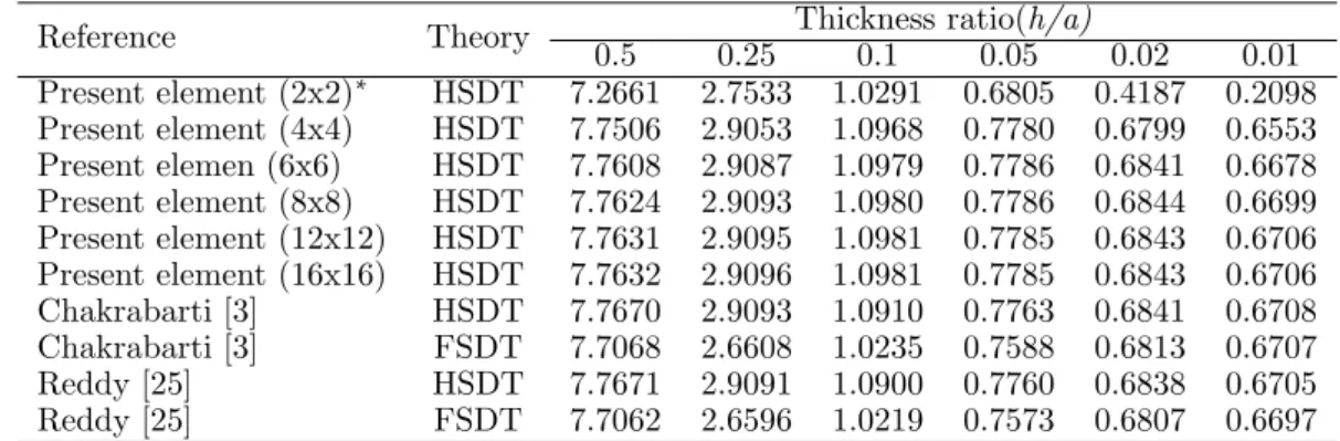
The problem of a three ply (0/90/0) square laminate, simply supported at all the edges and subjected to uniformly distributed load, is studied for different thickness ratio (h/a) ranging from 0.01 to 0.5. The plate is analyzed with different mesh divisions and the deflection obtained at the plate centre is presented with the analytical solution of Reddy [25] and Chakrabarti et al. [3] in Table 1. The result obtained shows the element is capable of predicting results with sufficient accuracy. In this it is observed that the first order shear deformation theory gives lesser deflections as compared to higher order shear deformation theory.
Table 1 Deflection (100wh3E2/qa4) at the centre of a simply supported square laminate (0/90/0) under uniform load of intensityq.
Reference Theory 0.5 0.25 Thickness ratio(h/a)0.1 0.05 0.02 0.01
Present element (2x2)∗
HSDT 7.2661 2.7533 1.0291 0.6805 0.4187 0.2098 Present element (4x4) HSDT 7.7506 2.9053 1.0968 0.7780 0.6799 0.6553 Present elemen (6x6) HSDT 7.7608 2.9087 1.0979 0.7786 0.6841 0.6678 Present element (8x8) HSDT 7.7624 2.9093 1.0980 0.7786 0.6844 0.6699 Present element (12x12) HSDT 7.7631 2.9095 1.0981 0.7785 0.6843 0.6706 Present element (16x16) HSDT 7.7632 2.9096 1.0981 0.7785 0.6843 0.6706 Chakrabarti [3] HSDT 7.7670 2.9093 1.0910 0.7763 0.6841 0.6708 Chakrabarti [3] FSDT 7.7068 2.6608 1.0235 0.7588 0.6813 0.6707 Reddy [25] HSDT 7.7671 2.9091 1.0900 0.7760 0.6838 0.6705 Reddy [25] FSDT 7.7062 2.6596 1.0219 0.7573 0.6807 0.6697
∗Entries inside the parenthesis indicate mesh division
Although the individual layers possess different orientations but they have equal thickness and material property (E1= E2 = 25; G12 = G13 = 0.5E2, G23 = 0.2E2, ν12 = 0.25 and
4.1.2 Cross-ply rectangular laminate subjected to distributed load of sinusoidal variation
The plate is modeled by the proposed element using the mesh arrangement as shown in Figure 3. This mesh arrangement is used in all the examples where the plate is rectangular. A rect-angular laminate subjected to a load having a distribution ofq(x, y) = q0sin(πx/a)sin(πy/b)
is considered in this example. The stacking sequence and boundary conditions are identical to those taken in the previous example. The study is made by taking thickness ratio (h/a)as 0.5, 0.1 and 0.01.
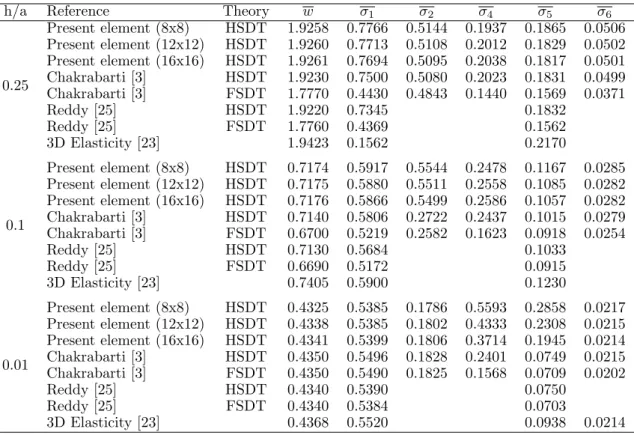
In all the cases the analysis is done with three different mesh divisions and the deflection and stress components obtained at the important locations are presented with the analytical solution of Reddy [25] and numerical solution of Chakrabarti et al. [3] in Table 2. The deflection and stress results of the element are exactly in agreement with the published results.
Table 2 Non-dimensional deflection and stresses at important points of a simply supported square laminate (0/90/0) under sinusoidal loading of amplitudeq.
h/a Reference Theory w σ1 σ2 σ4 σ5 σ6
0.25
Present element (8x8) HSDT 1.9258 0.7766 0.5144 0.1937 0.1865 0.0506 Present element (12x12) HSDT 1.9260 0.7713 0.5108 0.2012 0.1829 0.0502 Present element (16x16) HSDT 1.9261 0.7694 0.5095 0.2038 0.1817 0.0501 Chakrabarti [3] HSDT 1.9230 0.7500 0.5080 0.2023 0.1831 0.0499 Chakrabarti [3] FSDT 1.7770 0.4430 0.4843 0.1440 0.1569 0.0371
Reddy [25] HSDT 1.9220 0.7345 0.1832
Reddy [25] FSDT 1.7760 0.4369 0.1562
3D Elasticity [23] 1.9423 0.1562 0.2170
0.1
Present element (8x8) HSDT 0.7174 0.5917 0.5544 0.2478 0.1167 0.0285 Present element (12x12) HSDT 0.7175 0.5880 0.5511 0.2558 0.1085 0.0282 Present element (16x16) HSDT 0.7176 0.5866 0.5499 0.2586 0.1057 0.0282 Chakrabarti [3] HSDT 0.7140 0.5806 0.2722 0.2437 0.1015 0.0279 Chakrabarti [3] FSDT 0.6700 0.5219 0.2582 0.1623 0.0918 0.0254
Reddy [25] HSDT 0.7130 0.5684 0.1033
Reddy [25] FSDT 0.6690 0.5172 0.0915
3D Elasticity [23] 0.7405 0.5900 0.1230
0.01
Present element (8x8) HSDT 0.4325 0.5385 0.1786 0.5593 0.2858 0.0217 Present element (12x12) HSDT 0.4338 0.5385 0.1802 0.4333 0.2308 0.0215 Present element (16x16) HSDT 0.4341 0.5399 0.1806 0.3714 0.1945 0.0214 Chakrabarti [3] HSDT 0.4350 0.5496 0.1828 0.2401 0.0749 0.0215 Chakrabarti [3] FSDT 0.4350 0.5490 0.1825 0.1568 0.0709 0.0202
Reddy [25] HSDT 0.4340 0.5390 0.0750
Reddy [25] FSDT 0.4340 0.5384 0.0703
3D Elasticity [23] 0.4368 0.5520 0.0938 0.0214
4.2 Analysis of composites and sandwich laminates based on refined higher order shear deformation theory
improve-ment specifically for the stresses evaluation to have a comparable value with 3-D elasticity solution Pagano [23]. This improvement is shown in this section by solving some problems of composites and sandwich laminates with the proposed element based on refined higher order shear deformation theory by compensatingC0
continuity in stiffness matrix calculations.
4.2.1 Simply supported cross-ply square laminate
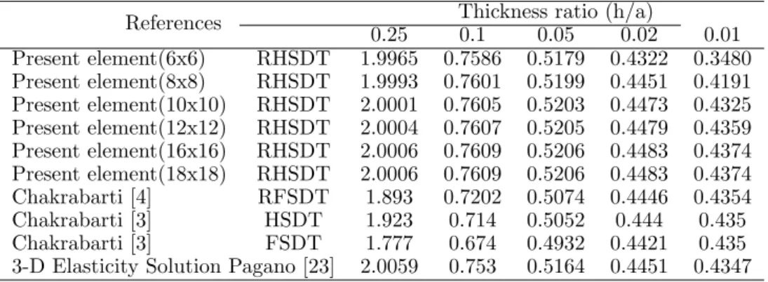
In order to show the performance of different plate theories a cross-ply (0/90/0) laminate (Figure 3, a = b) subjected to a uniformly distributed load of intensity q(x, y) = q0 sin (πx/a) sin (πy/b) is considered in this example. The full plate is analyzed with different mesh divisions. The results obtained are compared with those obtained by First order Shear Deformation Theory (FSDT), HSDT, RFSDT (Refined FSDT) and 3D elasticity solution. Table 3 shows the present values of central deflectionswc=100wE2h
3 /(q0a
4
)based on RHSDT are close to the 3D elasticity solution while the FSDT gives the worst results.
Table 3 Central deflection (wc) of a simply supported cross-ply (0/90/0) square laminate under sinusoidal
loading.
References 0.25 Thickness ratio (h/a)0.1 0.05 0.02 0.01
Present element(6x6) RHSDT 1.9965 0.7586 0.5179 0.4322 0.3480 Present element(8x8) RHSDT 1.9993 0.7601 0.5199 0.4451 0.4191 Present element(10x10) RHSDT 2.0001 0.7605 0.5203 0.4473 0.4325 Present element(12x12) RHSDT 2.0004 0.7607 0.5205 0.4479 0.4359 Present element(16x16) RHSDT 2.0006 0.7609 0.5206 0.4483 0.4374 Present element(18x18) RHSDT 2.0006 0.7609 0.5206 0.4483 0.4374 Chakrabarti [4] RFSDT 1.893 0.7202 0.5074 0.4446 0.4354 Chakrabarti [3] HSDT 1.923 0.714 0.5052 0.444 0.435 Chakrabarti [3] FSDT 1.777 0.674 0.4932 0.4421 0.435 3-D Elasticity Solution Pagano [23] 2.0059 0.753 0.5164 0.4451 0.4347
4.2.2 Simply supported cross-ply square laminate
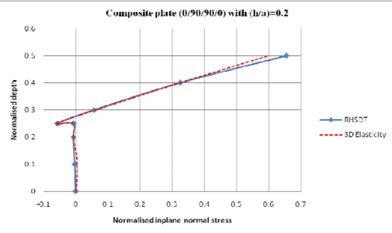
The problem of a cross-ply (0/90/90/0) laminated plate (Figure 3, a = b) subjected to a distributed load of intensity of q(x, y) = q0 sin (πx/a) sin (πy/b) is taken in this example. The variation of normal stress (σx=σxh2/(q0a2)) across the thickness of the plate is presented
in Figure 4 with those obtained by 3D elasticity solution [8]. The potential of the element is clearly reflected in the accuracy exhibited in the prediction of stress distribution. The in-plane shear stress,τxy =τxyh
2
/(qa2) at the corner of the plate and the transverse shear stress
τxz =τxzh/(q0a) at the centre of the edge of the plate is obtained by RHSDT and is plotted
Figure 4 Variation of in plane normal stress across the plate thickness for simply supported square composite plate (0/90/90/0) under sinusoidal loading.
Figure 5 Variation of in plane shear stress across the plate thickness for simply supported square composite plate (0/90/90/0) under sinusoidal loading.
4.2.3 Simply supported rectangular laminated sandwich plate under distributed load of sinusoidal variation
A rectangular sandwich plate (0/90/C/0/90) plate (Figure 3) is subjected to a sinusoidal load of intensityq =q0 sin(x/a) sin(y/b). It has a total thickness of h where the thickness of the core is 0.8h and that of each ply in the top and bottom face sheets is 0.05h. The plate is analyzed by taking aspect ratiob/a=1.0 and 2.0 and thickness ratiosh/a = 0.1 and 0.2 using different mesh sizes. The material properties used for the core and each laminated face sheets are given in Table 4. The non-dimensional values of central deflection w(a2,2b,0)obtained in the present analysis are presented with those obtained from the three-dimensional elasticity solution in Table 5.
Table 4 Material properties used for core and face sheets.
Location Elastic properties
E1 E2 E3 G12 G13 G23 ν12
Core 0.04E 0.04E 0.5E 0.016E 0.06E 0.06E 0.25 Face 25E E - 0.5E 0.5E 0.2E 0.25
As regard to three-dimensional elasticity solution [8], it is relevant to mention that the numerical results based on elasticity solution used here for the comparison are not readily available in the paper of Pagano [3] and hence a software code is used to generate results. The present results are in very good agreement with the elasticity solution [3]. Table 5 also shows that the convergence of the results with mesh refinement is excellent.
Table 5 Non dimensional deflection (wc) of square sandwich plate (0/90/C/0/90) under sinusoidal load.
Reference Theory
Aspect ratio
1 2
4.2.4 Simply supported square sandwich plate under sinusoidal load
A square sandwich (0/C/0) plate, simply supported at all four edges and subjected to dis-tributed load of intensity q = q0 sin(x/a) sin(y/b) is analyzed by taking thickness ratios,
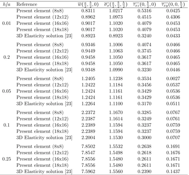
h/a = 0.01, 0.02, 0.05 and 0.25. The thickness of each face is 0.1h. The material properties are as given in Table 4. The deflection, the normal stresses and the shear stresses at some important points obtained by the present formulation are presented in Table 6 along with the three-dimensional elasticity solution of Pagano [23]. The study has been performed for different mesh divisions to show the convergence characteristics. In general present results are close to the elasticity solution with good convergence.
Table 6 Non-dimensional deflection (wc) and stresses(σx, σxz, σxy)at important points of a simply supported
square sandwich plate (0/C/0) under sinusoidal loading. h/a Reference w(a2,2b,0) σx(a2,
b
2,
h
2) τxz(0,
b
2,0) τxy(0,0,
h
2)
0.01
Present element (8x8) 0.8311 1.0217 0.5316 0.0425 Present element (12x12) 0.8962 1.0973 0.4515 0.4306 Present element (16x16) 0.9017 1.1020 0.4079 0.0453 Present element (18x18) 0.9017 1.1020 0.4079 0.0453 3D Elasticity solution [23] 0.8923 0.8923 0.3240 0.0433
0.2
Present element (8x8) 0.9346 1.1006 0.4074 0.0466 Present element (12x12) 0.9449 1.1063 0.3745 0.0466 Present element (16x16) 0.9458 1.1050 0.3617 0.0465 Present element (18x18) 0.9458 1.1050 0.3617 0.0465 3D Elasticity solution [23] 0.9348 1.0990 0.3230 0.0446
0.05
Present element (8x8) 1.2405 1.1238 0.3534 0.0027 Present element (12x12) 1.2422 1.1184 0.3456 0.0537 Present element (16x16) 1.2424 1.1161 0.3429 0.0536 Present element (18x18) 1.2424 1.1161 0.3429 0.0536 3D Elasticity solution [23] 1.2264 1.1100 0.3170 0.0511
0.1
Present element (8x8) 2.2372 1.1670 0.3285 0.0767 Present element (12x12) 2.2387 1.1614 0.3249 0.0761 Present element (16x16) 2.2389 1.1594 0.3237 0.0759 Present element (18x18) 2.2389 1.1594 0.3237 0.0759 3D Elasticity solution [23] 2.2004 1.1530 0.3000 0.0707
0.25
4.2.5 Sandwich plate having different boundary conditions under distributed load of sinusoidal variation
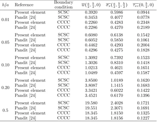
A sandwich plate (0/90/C/0/90) subjected to a distributed load of intensity q=q0 sin(x/a) sin(y/b) is analyzed in this example. It has a total thickness of h where the thickness of the core is0.8h and that of each ply in the top and bottom face sheets is 0.05h. The study has been made for two types of boundary conditions. These are SCSC, i.e. two opposite edges simply supported and other two edges clamped and CCCC, i.e. all edges clamped. The analysis is performed for different thickness ratios (h/a = 0.01, 0.05, 0.10, 0.20 and 0.50). The material properties used for the core and each laminated face sheets are given in Table 4. The non-dimensional values of central deflection and the stresses calculated at the important points are presented in Table 7.
It may be noted from the results that the percentage increase in the transverse displacement for higher thickness ratios, i.e. from 0.20 to 0.50 is much higher than those for lower thickness ratios, i.e. from 0.01 to 0.05 for both the boundary conditions. The major cause behind it may be that for higher thickness ratios the effect of transverse flexibility of the core and shear deformation effects are more pronounced as compared with that of the lower thickness ratio.
Table 7 Non-dimensional deflection (wc) and stresses (σx, σxz)at important points of a square sandwich
plate (0/90/C/0/90) under sinusoidal loading with different boundary conditions.
h/a Reference Boundarycondition w(a2,
b
2,0) σx(
a
2,
b
2,
h
2) τxz(0,
b
2,0)
0.01
Present element SCSC 0.3920 0.5986 0.0944
Pandit [24] SCSC 0.3453 0.4077 0.0778
Present element CCCC 0.2260 0.4283 0.2348
Pandit [24] CCCC 0.2286 0.4270 0.2189
0.05
Present element SCSC 0.6080 0.6138 0.1542
Pandit [24] SCSC 0.6052 0.5850 0.1061
Present element CCCC 0.4462 0.4293 0.2004
Pandit [24] CCCC 0.4296 0.4275 0.1828
0.10
Present element SCSC 1.3092 0.7392 0.1523
Pandit [24] SCSC 1.3026 0.8310 0.1418
Present element CCCC 1.0213 0.4621 0.1651
Pandit [24] CCCC 1.0489 0.4597 0.1587
0.20
Present element SCSC 3.8500 1.0189 0.1620
Pandit [24] SCSC 3.8087 1.1415 0.1683
Present element CCCC 3.3421 0.6022 0.1422
Pandit [24] CCCC 3.4521 0.6170 0.1396
0.5
Present element SCSC 19.580 2.4028 0.1721
Pandit [24] SCSC 19.551 2.3071 0.1691
Present element CCCC 18.345 1.8150 0.1325
5 CONCLUSIONS
An efficient FE model based on higher order zigzag theory (RHSDT) is presented for the analy-sis of composites and sandwich plates. The present zigzag theory ensures shear free conditions at the top and bottom of the plate, cubic variation of the in-plane displacements and inter-laminar shear stress continuity at the layer interfaces. An eight node isoparametric element with seven degrees of freedom per node is adopted in this study to model the RHSDT. Con-vergence of the results is very good indicating reasonably less number of elements required to get the desired results. The results obtained for the deflections and the stresses of a laminated composite and sandwich plate show very good performance of the present formulation and hence it can be recommended for the accurate analysis of laminated composites and sandwich plates.
References
[1] K. Bhaskar and T.K. Varadan. Refinement of higher order laminated plate theories. AIAA J, 27:1830–1831, 1989.
[2] E. Carrera. On the use of the Murakami’s zig-zag function in the modeling of layered plates and shells. Compos. Struct., 82:541–554, 2004.
[3] A. Chakrabarti and A.H. Sheikh. A new plate bending element based on higher order shear deformation theory for the analysis of composite plates. Fin. Elem. Anal. Des., 39(9):883–903, 2003.
[4] A. Chakrabarti and A.H. Sheikh. Analysis of laminated sandwich plates based on interlaminar shear stress continuous plate theory.J. Eng. Mech. ASCE, 131(4):377–384, 2005.
[5] M. Cho and J. Oh. Higher-order zig-zag theory for fully coupled thermoelectro-mechanical smart composite plates.
Int. J. Solids Struct., 41:1331–56, 2004.
[6] M. Cho and R.R. Parmerter. An efficient higher order plate theory for laminated composites. Compos. Struct., 20:113–123, 1992.
[7] M. Cho and R.R. Parmerter. Efficient higher order composite plate theory for general lamination configurations.
AIAA J, 31(7):1299–1306, 1993.
[8] Robert D. Cook, David S. Malkus, Plesha E. Michael, and Robert J. Witt. Concepts and Applications of Finite Element Analysis. John Wiley & Sons Pte. Ltd., 4th edition, 2003.
[9] Liu D. and Li X. An overall view of laminate theories based on displacement hypothesis. J. Compos. Mater., 30:1539–1561, 1996.
[10] Isaac M. Daniel and Ishai Ori.Engineering Mechanics of Composite Materials. Oxford University Press, 2nd edition, 2006.
[11] L. Demasi. Refined multilayered plate elements based on Murakami zig-zag functions. Compos. Struct., 70:308–316, 2005.
[12] L. Demasi. Mixed plate theories based on generalized unified formulation Part IV: zig-zag theories.Compos. Struct., 87:195–205, 2009.
[13] L. Demasi. Mixed plate theories based on generalized unified formulation. Part V: Results.Compos. Struct., 88:1–16, 2009.
[14] M. Di Sciuva. A refined transverse shear deformation theory for multilayered anisotropic plates. Atti. Academia Scienze Torino, 118:279–295, 1984.
[15] M. Di Scuiva. Multilayered anisotropic plate models with continuous interlaminar stress.Comput. Struct., 22(3):149– 167, 1992.
[16] S. Kapuria and G.G.S. Achary. A coupled zigzag theory for the dynamics of piezoelectric hybrid cross-ply plates.
[17] S. Kapuria, P.C. Dumir, and A. Ahmed. Efficient coupled zigzag theory for hybrid piezoelectric beams for thermo-electric load.AIAA J, 42:383–394, 2004.
[18] X. Li and D. Liu. Zigzag theory for composite laminates. AIAA J, 33(6):1163–1165, 1995.
[19] K.H. Lo, R.M. Christensen, and E.M. Wu. A higher order theory of plate deformation, Part 2. Laminated plates.J. Appl. Mech. Trans., ASME, 44:669–676, 1977.
[20] B.S. Manjunatha and T. Kant. A comparison of nine and sixteen noded quadrilateral elements based on higher order laminate theories for estimation of transverse stresses. J. Reinf. Plast. Compos., 11:986–1002, 1992.
[21] H. Murakami. Laminated composite plate theory with improved in-plane response.J. Appl. Mech. ASME, 53:661–6, 1986.
[22] H. Murakami. Laminated composite plate theory with improved in-plane responses. J. Appl. Mech., 53:661–666, 1986.
[23] N.J. Pagano. Exact solution for rectangular bidirectional composites and sandwich plates. J. Compos. Mater., 4:20–34, 1970.
[24] M.K. Pandit, A.H. Sheikh, and B.N. Singh. An improved higher order zigzag theory for the static analysis of laminated sandwich plate with soft core. Fin. Elem. Anal. Des., 44:602–610, 2008.
[25] J.N. Reddy. A simple higher-order theory for laminated composite plates.J. Appl. Mech. Trans. ASME, 51:745–752, 1984.
[26] E. Reissner. On the theory of bending of elastic plates. J. Math. Phys., 23:184–191, 1944.
[27] D.H. Robbins and J.N. Reddy. Modeling of thick composites using a layerwise laminate theory. Int. J. Numer. Methods Eng., 36:655–677, 1993.
[28] C.A. Shankara and N.G.R. Iyengar. Ac0 element for the free vibration analysis of laminated composite plates. J.
Sound Vib., 191(5):721–738, 1996.
[29] S. Srinivas. A refined analysis of composite laminates. J. Sound Vibr., 30:495–507, 1973.
[30] A. Toledano and H. Murakami. A composite plate theory for arbitrary laminate configuration. J. Appl. Mech., 54:181–189, 1987.
[31] S. Vlachoutsis. Shear correction factors for plates and shells.Int. J. Num. Methods Eng., 33(7):1537–1552, 1992.
[32] P.C. Yang, C.H. Norris, and Y. Stavsky. Elastic wave propagation in heterogeneous plates. Int. J. Solids Struct., 2:665–684, 1966.
[33] W. Zhen and C. Wanji. Ac0-type higher-order-theory for bending analysis of laminated composite and sandwich plates. Compos. Struct., 92:653–661, 2010.