Flexible Industrial Robotized
Cells
Marcos Ferreira
Doctoral Program in Electrical and Computer Engineering Supervisor: Ant´onio Paulo Gomes Mendes Moreira Co-Supervisor: Joaquim Norberto Cardoso Pires da Silva
A thesis submitted for the degree of Doctor of Philosophy (PhD)
Industrial manipulators play a key role on major production lines. They are one of the most powerful automation solutions for flexible mass production, delivering efficiency and quality at reduced prices. In an entirely different scene, there are the small and medium enterprises (SMEs), which mostly rely on high skilled labour, delivering less quantity but increased customiza-tion. In the face of modernization, and to sustain global competitiveness, SMEs are increasingly adopting robotized solutions. Yet, despite of the numerous researches and contributions to improve human-robot interface, programming an industrial robot is still a very technical and time-consuming challenge.
On this scenario, this thesis sets focus on developing new means of intuitive and high level robot programming. Specifically, a new method for robot programming by demonstration is proposed: the factory operator demon-strates a given task, and the robot is automatically programmed to mimic the human operation. This is a framework for human-robot skill transfer, since the know-how of the operator is translated into robot language. Addi-tionally, the final solution is designed and optimized for maximum industrial applicability: use of low-cost hardware, low impact on the industrial pro-cess, high success rate and accuracy, fast (real-time) output.
generating the robot program.
Os manipuladores industriais tˆem um papel preponderante nas grandes lin-has de produ¸c˜ao. S˜ao uma das solu¸c˜oes mais avan¸cadas tendo em vista o conceito de produ¸c˜ao em massa flex´ıvel, produzindo com eficiˆencia e qual-idade a um custo reduzido. Num outro cen´ario completamente diferente encontram-se as pequenas e m´edias empresas, PMEs, que dependem funda-mentalmente da m˜ao de obra qualificada dos seus trabalhadores, produzem em menor quantidade mas com maior grau de customiza¸c˜ao. Na perspectiva de se modernizarem, e de forma a manterem a competitividade no mercado global, as PMEs tˆem vindo cada vez mais a apostar na robotiza¸c˜ao dos seus processos. Contudo, apesar de toda a investiga¸c˜ao em torno da cria¸c˜ao de novos m´etodos para melhorar o interface homem-robˆo, a programa¸c˜ao de um manipulador industrial ainda requer um elevado n´ıvel de conhecimento t´ecnico para al´em de ser uma tarefa morosa.
´
E neste cen´ario que esta tese pretende contribuir, desenvolvendo m´etodos intuitivos para a programa¸c˜ao de robˆos industriais. Mais especificamente, ´e proposto um novo m´etodo para programa¸c˜ao por demonstra¸c˜ao: o operador humano demonstra uma determinada tarefa e o robˆo ´e automaticamente programado de modo a que consiga imitar o movimento humano. No seu todo, esta solu¸c˜ao consiste numaframework para transferˆencia deknow-how do operador humano para o robˆo. Mais ainda, a solu¸c˜ao final ´e projetada e otimizada do ponto de vista da aplicabilidade industrial: ´e usado equipa-mento de baixo custo, o impacto no processo ´e m´ınimo, apresenta elevada exatid˜ao e taxa de sucesso, o resultado ´e obtido em tempo real.
permitindo assim uma leitura precisa e robusta do marcador, mesmo em condi¸c˜oes adversas t´ıpicas de um ambiente industrial. Um conjunto de al-goritmos otimizados para a forma e cor dos marcadores permite fazer uma reconstru¸c˜ao da trajet´oria com seis graus de liberdade (6 DoF) — posi¸c˜ao e orienta¸c˜ao. Antes da gera¸c˜ao do c´odigo para o manipulador industrial, a trajet´oria ´e ainda suavizada usando B-Splines em 3D e splines no espa¸co dos quaterni˜oes.
never forget it.
Carl Sagan
First and foremost I must thank my supervisors, Professor A. Paulo Moreira and Professor Norberto Pires, for their guidance. To Professor Norberto, whose extensive and remarkable work on the field of robotics served as an inspiration for my research. To Professor A. Paulo, to whom I owe a great debt of gratitude for all this years of advice, support and friendship. His enthusiasm for research, his liveliness and his faithfulness in my work were a major motivation for me.
I would like to thank everyone in the Robotics and Intelligent Systems Unit (Robis) of INESC-TEC. They are the most amazing colleagues and they make of Robis laboratory the most interesting place to work at. A special word of gratitude for my labmates Heber Sobreira, Miguel Pinto, Filipe Santos, Andr´e Figueiredo, Lu´ıs Rocha and Germano Veiga for sharing their knowledge and friendship over these past years. My sincere thanks to Lu´ıs Rocha for all the help, the availability, and for enduring many hours of frustration setting up the industrial solution. Furthermore, I’m also grateful to Germano Veiga for all the insightful discussions, for sharing his experience, and for taking time to examine my work and questioning it. I would also like to give my sincerest thanks to my friends Paulo Malheiros and Professor Paulo Costa. To Paulo Malheiros, I thank him for all his support and for being the most helpful labmate. And also, because I was able to develop my research upon the basis of his work. To Professor Paulo Costa, I thank him for all the guidance, the most useful suggestions and ideas, and for all those late night discussions which proved to be utterly valuable.
and validating my research as well as to ultimately spread words of its success. I thank all of Flupol’s staff, and particularly Rui Gomes, for their help and care.
I will take this opportunity to express my appreciation to all Professors of DEEC/FEUP who contributed to my pursuit of knowledge. I am very fortunate to have crossed paths and to have being taught by such brilliant minds and distinctive characters, encountering some odd personalities along the way.
Finally, my last acknowledgements are the most heartfelt. I ought to thank my close family and friends. Although I do not usually share much of my academic and professional life with them, I still hope to feel their comfort at the end of the day and to embrace their love and friendship in every step of my way. And you Sara. . . I just can’t put it into words; a thousand would be too few. Thank you for being there.
To all, thank you so very much.
Marcos Ferreira acknowledges FCT (Portuguese Foundation for Science and Technology) for his PhD grant SFRH/BD/60221/2009, without which this research work would not have been possible.
The work presented in this thesis, being part of the Project PRODUTECH PTI (number 13851) - New Processes and Innovative Technologies for the Production Technologies Industry, has been partly funded by the Incentive System for Technology Research and Development in Companies (SI I&DT), under the Competitive Factors Thematic Operational Programme, of the Portuguese National Strategic Reference Framework, and EU’s European Regional Development Fund.
Additionally, this work was also sponsored by the project QREN-SIIARI. SIIARI - Sistema para o Incremento da Inteligˆencia Artificial em Rob´otica Industrial (QREN- Quadro de Referˆencia Estrat´egico Nacional) 2010-2012.
The author also thanks the FCT for supporting this work through the project PTDC/EME-CRO/114595/2009 - High-Level programming for in-dustrial robotic cells: capturing human body motion.
List of Figures xvii
List of Tables xxi
1 Introduction 1
1.1 On the use of industrial robotic manipulators . . . 1
1.1.1 The quest for human-robot interfaces . . . 4
1.2 Motivation . . . 5
1.2.1 A case study . . . 7
1.3 Proposed Solution/Aims . . . 8
1.3.1 A Previous Approach . . . 9
1.4 Thesis Outline . . . 10
2 Related Work 13 2.1 Programming Industrial Robots: the Teach Pendant and Simulators . . 14
2.2 Taking advantage of CAD . . . 17
2.3 Programming by motion demonstration . . . 19
3 Background and Notation 25 3.1 Matrix Notation . . . 25
3.2 Coordinate Systems, frames and transformations . . . 26
3.2.1 Homogeneous Coordinate System . . . 27
3.2.2 Orientation of a Rigid Body: representations . . . 29
3.3 3D computer vision . . . 33
3.3.1 Camera Model . . . 34
3.3.3 Camera/Stereo Calibration . . . 39
3.3.4 Tracking Luminous Markers — Thesincrovision . . . 40
3.4 Industrial Manipulators . . . 41
4 Motion Imitation Framework 45 4.1 System Architecture : Overview . . . 45
4.2 Camera and Stereo Calibration . . . 47
4.3 Motion Tracking . . . 51
4.3.1 6-DoF Marker . . . 51
4.3.1.1 Description: Hardware and Properties . . . 52
4.3.1.2 Detection . . . 57
4.3.1.3 Per-Image Analisys . . . 57
4.3.1.4 Stereo — cluster matching . . . 63
4.3.1.5 Estimating Position . . . 66
4.3.1.6 Estimating Orientation . . . 72
4.3.1.7 Limitations . . . 76
4.4 Interfacing an Industrial Manipulator . . . 78
4.4.1 Data Filtering . . . 78
4.4.1.1 Position Smoothing . . . 78
4.4.1.2 Orientation Smoothing . . . 87
4.4.2 Path Segmentation . . . 90
4.4.3 Automatic Code Generation . . . 97
5 Tests and Results 101 5.1 Industrial Demonstrator — Setup and Hardware . . . 101
5.2 Tests and Results . . . 105
5.2.1 Camera Calibration . . . 105
5.2.2 Marker Detection . . . 108
5.2.2.1 Colour Calibration . . . 108
5.2.2.2 Detection and Pose Estimation . . . 110
5.2.3 Marker Accuracy in the Workspace . . . 114
5.2.4 Filtering and Smoothing . . . 115
6 Conclusions 131
6.1 Global Assessment and Conclusions . . . 131 6.2 Future Work . . . 133
1.1 Industries purchasing robots . . . 2
1.2 Industrial Robots . . . 3
2.1 Teach Pendants . . . 15
2.2 Glove . . . 21
2.3 Input devices . . . 23
3.1 Frames . . . 27
3.2 Frames translation and rotation . . . 28
3.3 Homogeneous Coordinates . . . 30
3.4 Image Notation . . . 34
3.5 Camera Pinhole Model . . . 35
3.6 Stereoscopy . . . 37
3.7 Calibration Pattern . . . 40
3.8 Sincrovision Timings . . . 41
3.9 Sincrovision effect . . . 42
4.1 Camera and Stereo Calibration Using the Industrial Robot . . . 49
4.2 Precision/Repeatability vs Accuracy . . . 51
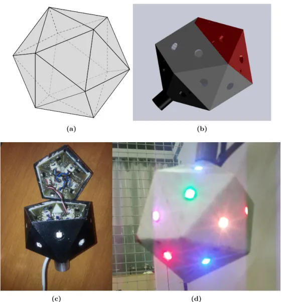
4.3 Icosahedron: 3D shape, CAD model and real marker . . . 53
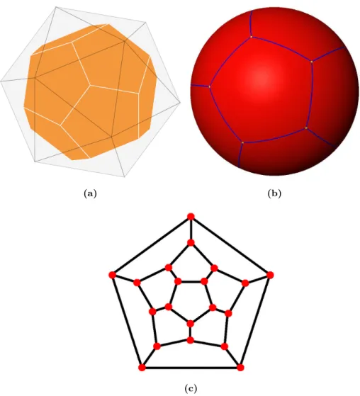
4.4 Icosahedron/Dodecahedron properties . . . 55
4.5 Marker applications . . . 56
4.6 Marker Electronics . . . 58
4.7 Stereo Capture and Normal Photo . . . 59
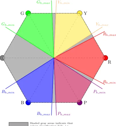
4.8 HSV color model . . . 60
4.10 HSV Calibration Example and Detection . . . 63
4.11 Pixel/Cluster Correspondence By Colour And Epipolar Line Constraint 65 4.12 Multiple matches . . . 66
4.13 3D Scene with LEDs and a Sphere . . . 67
4.14 Sphere Fitting — 3D representation . . . 71
4.15 The Dodecahedron Coloured Graph . . . 74
4.16 Synchronization across images and devices . . . 79
4.17 Piecewise Linear Approximation of Noisy Path . . . 80
4.18 B-Spline Cubic Basis Function . . . 82
4.19 B-Spline smoothing and a real path in a spray painting application . . . 86
4.20 lerp and Slerp interpolation . . . 88
4.21 Slerp and Squad interpolation for a path of rotations . . . 90
4.22 Trajectory Segmentation Based on I/O Changes . . . 91
4.23 Moving linearly to each point . . . 92
4.24 Segmentation of backtracks using 4D line fitting . . . 95
4.25 Trajectory Segmentation in Linear Movements . . . 96
4.26 Tweaking the Robot Trajectory Controller Tolerance . . . 98
4.27 Automatic Robot Program Generation . . . 99
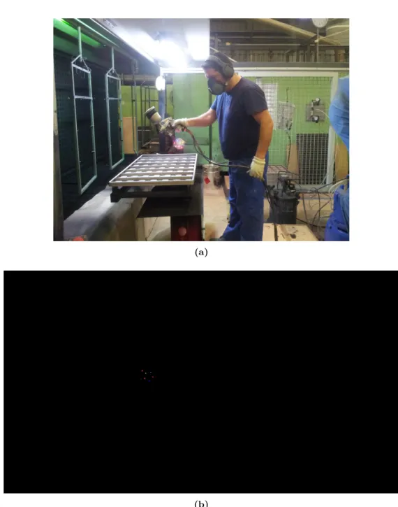
5.1 Human Painter in Flupol Coating Cell . . . 102
5.2 Robot in Flupol Coating Cell . . . 103
5.3 Marker Attached to the Industrial Spray Painting Gun . . . 103
5.4 Two Camera Arrangement for Stereoscopy . . . 104
5.5 CAD Model of the Calibration Tool . . . 106
5.6 Error variation in theX axis . . . 109
5.7 Error variation in theY axis . . . 109
5.8 Error variation in theZ axis . . . 110
5.9 HSV Colour Classes Calibration . . . 111
5.10 A Baking Tray . . . 116
5.11 B-Spline Smoothing of a Baking Tray Painting Path . . . 117
5.12 B-Spline vs Piecewise Linear Side View . . . 118
5.13 B-Spline vs Piecewise Linear Opposite View . . . 118
5.15 B-Spline Evaluation . . . 120
5.16 Sampling of the B-Spline at the Same Frequency of the Tracking . . . . 121
5.17 Sampling of the B-Spline at 2 times the Tracking Frequency . . . 122
5.18 Sampling of the B-Spline at 4 times the Tracking Frequency . . . 123
5.19 Sampling of the B-Spline at 8 times the Tracking Frequency . . . 124
5.20 Path decomposed intoX(t),Y (t) and Z(t) . . . 125
5.21 B-Spline smoothing ofX(t),Y (t) and Z(t) . . . 126
4.1 Cluster data after processing images from both cameras . . . 64
4.2 Marker Position Estimation . . . 69
4.3 Dodecahedron Vertices . . . 75
5.1 Calibration error onx,y andz axis . . . 107
5.2 Calibration error . . . 107
5.3 Number of misclassification of image clusters sorted by colour . . . 112
5.4 Evaluation of the position and orientation estimation . . . 113
5.5 Marker position error onx,y andz axis . . . 114
5.6 Marker pose error . . . 115
5.7 Sampling of the B-Spline Curve . . . 122
Introduction
1.1
On the use of industrial robotic manipulators
Industrial robotic manipulators are, as of today, a fully grown commercial off-the-shelf product that integrate the largest and most complex manufacturing facilities world-wide. These machines are taken as the ultimate automation tool:
A powerful and robust mechanical solution, fit to most demanding operations — heavyweight cargo lifting and handling, ability to sustain hazardous environments, full 24h work-shift.
Top grade electronics using state of the art sensors and motion controllers — high precision, high production quality and speed; integration with the most recent vision, laser and force sensing technologies to satisfy the most heterogeneous systems.
Dedicated software and user interfaces — the manipulators can be reprogrammed on-site, adapted to different work objects, configured with different grippers and tools; in short, they can be recycled on and on through a number of distinct applications.
Robots are the way to go in an ever increasing competitive market. But is it always so? Precision, quality and robustness all come with the pack, i.e they are bought with the industrial machine. Flexibility, however, it is an entirely different matter that may cost huge extras.
In fact, that stands true on one face of today’s industry: the large scale produc-tion, the large companies, the major markets. As depicted in Fig. 1.1, the electri-cal/electronics (PCs, TVs, cellphones) industry, rubber/plastic, metal/machinery and particularly the automotive industries are the most relevant purchasers of industrial robots.
Figure 1.1: Industries purchasing robots- Estimated wordwide annual supply (taken from [1])
certain and undisputed. Flexibility, in this scenario, means that robots can do the tedious and repetitive tasks humans would have to do otherwise; means calling in the programmer, weeks apart, to debug and correct the manipulation procedure or even change it completely to something else, instead of having to hire and teach an human operator for days. The 2012 annual report [1] from the International Federation of Robotics (IFR) shows the increasing use of industrial robots (Fig. 1.2, since the 2009 crisis and up until 2015(predicted)). Apart from the automotive industry, which has always been the major growth stimulator on process robotization, all other sectors are creating conditions to apply manipulators to their processes as they are seen as the prime tool for modernization, competitiveness and improvement of quality of work for human operators.
Figure 1.2: Industrial Robots- annual supply (taken from [1])
technol-ogy prices dropped low, companies started to modernize, the competition is at global level and above all, demand is different. Together, these factors led to the current mass customization trend. Production has to face smaller series with greater customization; consumers search the market for personalized goods, for tailored solutions. And few scenarios can be more dynamic than those based on customers tastes. Companies strive to answer this call and compete on the global market but this dynamic is costly: the production lines must constantly adapt to new processes; skilled operators take years to train. As such, the main work force is very limited. Moreover, mass customization does not work if the product price does not remain low. To achieve the required flexibility and low unit cost SMEs need no modernize; support their processes on automated and computer-aided systems; increase productivity with the same human labour. Robots do this at large companies. For SMEs, on the other hand, robots do not pose such an obvious solution. The long-term flexibility of manipulators do not fit the short-term de-mands. Reprogramming a robot takes too much time: a simple change in a pre-existing program takes hours and a full reconfiguration may require days. Furthermore, SMEs do not have the financial power to hire a full time skilled robot programmer. All of these represent extra cost for the enterprise: hiring of experts, automated machines, recurring configurations and the associated down-time. Before this scenario robots have a hard time penetrating and earning their place into small business.
1.1.1 The quest for human-robot interfaces
The research on this field has diverged into many streams. In the late years it has expanded over other robotic areas such as medical, domestic services, security... the appearance of humanoids led to a pursuit of ways to make the machine, made at our image, to behave like ourselves. But the research at industrial level as continued because there isn’t a solution that can fit the so many problems industry faces. Also, much of the state of the art contributions use technologies that are not prepared for industrial use, others are simply cost prohibitive. Chapter 2 presents an in depth view of the current developments in HRI and easy robot programming. Yet it must be noted that as the current market demands more of the companies, the research on this field must also be able to answer the call and support small and medium business, with new methods that facilitate the integration of robots in highly flexible processes.
1.2
Motivation
On the very same line of thought presented above, this dissertation was motivated by the lack of industrial grade solutions that enable intuitive and easy robot programming. The changes on the global market, the problem of small series production, cus-tomization, improving robot flexibility, etc... for years, contributions on this field have been supported by the same reasons, targeting the same goals. So why isn’t there a solution already? Processes change everyday, companies attack new markets, develop new products, new solutions. It is impossible to cover every area with a single system, a unique programming or interface method. Moreover, technology is getting cheaper everyday; automation of production lines becomes available at reduced costs. Despite existing numerous contributions there are always new sensors to explore, more recent machines to experiment.
Another motivational factor comes exactly with the industrial applicability of the existing or currently researched techniques. Flexible robotic manipulators can aid the most flexible business, SMEs. Yet this is where financial resources are the lesser. Pro-posed solutions must be affordable both in matters of money and time. The three major limitations that can be found on the proposed solutions found in literature (discussed on the next chapter) are:
Companies do need to improve production and quality but they also need to keep the cost low otherwise competitiveness is lost from the start. Robotization, i.e, acquiring the robot and re-designing production lines to fit it in is already a strong investment. The support technology, HRIs and intuitive programming software, cannot pose an equivalent financial burden.
• The dimension of the hardware apparatus and/or its inadequacy to industrial use. A grand part of the research work (on industrial manipulators) lacks actual industrial validation. Sometimes the hardware apparatus is inappropriate, fragile or it simply cannot deliver in an industrial environment — there are examples such as using retro-projectors to teach paths, which are equipments clearly not ready for dust, intensive work... the aggressiveness of the industrial environment; using IMUs (inertial measurement units) when, most of the times, the production lines or working tools are metallic and the sensor is most likely to fail; using special gloves requiring that the operator wears an object he is not used to work with and affects his performance; or even using vision systems that require major transformations in the workspace to control lighting thus being costly.
• Time. Many solutions base themselves on complex and computational intensive algorithms. In addiction to the required hardware (high-end PCs or PC grids) which are expensive alone, there is also the time it takes to interact with the robot or to generate paths, making it unaffordable. Productivity cannot cope with elevated downtime. Whether it is a gesture/voice recognition setup or a path demonstration system, a quick delivery is mandatory for increased produc-tivity. A 90-plus percent identification rate on a recognition-based interface still means that after a thousand work pieces or tasks almost a hundred failed; a path demonstration system that takes several minutes to process data from a minute-length task do not improve reconfiguration times – if the path has to be generated twice or a third time to perfect output, and it happens so for every different object, production efficiency drops instead of being boosted.
set of problems and they contribute by providing means of interacting with the machine. A more broader solution, one that would satisfy a larger set of applications, is one that can learn from the operator, him who knows best the process and procedure. Rather than giving a mean to communicate with the machine, give it the know-how. Factory operators hold all the expertise required to perfectly perform the task at hands; companies survive due to them, they are the major asset. So, instead of providing the operator with a way to speak to the robot intuitively, it is amazingly powerful to have the ability to transfer skill from man to machine.
1.2.1 A case study
This thesis has been particularly fuelled by a real industrial case scenario.
Flupol [3] is a Portuguese SME operating in the area of industrial coatings. Their applications range from house-ware utilities, automotive parts, baking industry, and up to any general industrial application where advanced coating is required (for surface adhesion, dry lubrication or corrosion prevention).
Its main asset lies on the application (spraying) of complex and delicate products which only a few extremely experienced operators are qualified to do. Hence, the major surplus comes from the operators’ know how. This is quite valuable since the company estimates that fully training new operators takes as much as 8 years. Right now, only a couple of employees are considered experts.
machines and cells must be constantly updated to make use of new automation devices. The next step: robotization.
This scenario is the most perfect match to the one presented in the previous sections: high skilled labour, highly flexible processes, constant reconfigurations... the need to increase competitiveness by boosting productivity while maintaining quality... the seek of increasingly automated solutions which, ultimately, cries for the industrial robot.
And if the urge for robots is true, so are the requirements and limitations of a flexible small company: hiring programmers is too expensive nor it delivers the required fast reconfigurations; typical operators stand as painters, not informatics – programming the robot must be the most intuitive.
Finally, the greatest question on this case: is it possible to transfer the skill of the painter over to the robot and avoid 8 years training of an operator? Can a 25-year-expertise badge be instantaneously transferred to the machine?
1.3
Proposed Solution/Aims
Against the panorama analysed above, to aid penetration of robots into the smaller business and with a real test case in hands, this thesis sets focus on developing an industrial grade human-robot skill transfer framework.
Starting on the target machine, the robot, the proposed system interfaces an off-the-shelf industrial manipulator: these are mature products whose cost, maintenance and technical support cannot be matched with home-made solutions. Standard industrial manipulators include years of refinement in motion control and security aspects. They are the most solid choice for the end product.
designed to have minimum impact on the process; operators execute the usual tasks with no interference from the hardware apparatus; this allows to completely capture the essence of the human know-how.
Put together, all elements are industrial grade and by industrial grade is it meant that the solution shall attend to the major industrial requirements: sensors, actuators and auxiliary hardware paraphernalia must be able to endure the environment; all the apparatus must be the less intrusive possible, i.e, not requiring major changes to the processes; also, the operator must be able to act naturally without major cares towards the sensing setup; the framework must deliver in real-time meaning that there can be no overhead in the algorithms – as soon as the operation is demonstrated by the human, the robot must be ready to replay it; the whole system must be low cost, using standard industrial equipment.
On the end, the proposed solution integrates a set of industrial cameras and a cheap luminous marker. Together these devices grant a robust capture of operator’s moves. Then, a set of computationally fast algorithms can determine the marker position and orientation. In a further step, the movement is analysed and segmented in order to be “written” in robot language. Finally, the robot is set to replay the same exact movement as made by the operator. From the users point of view, there is a complete abstraction of the robot programming language. The machine is programmed with no interaction with teach-pendants, code or any other sophisticated interfaces other than a “start/stop learning” button.
To test for the industrial capability of the framework, Flupol is used as the test bed. The skill transfer concept is applied to the spray coating application, where an experienced painter demonstrates the coating technique and the robot mimics him. The spraying over complex forms is replenished with technique and intricate wrist moves which serves the purpose of intensively validate the proposed framework.
1.3.1 A Previous Approach
parts travel on a conveyor and are scanned by the laser; then, a machine learning al-gorithm identifies the part and uploads the correct painting program into the robot controller. With this system it was expected that both the program generation and the reconfiguration for different pieces would occur in a simplified manner without using the robot teach pendant. Nonetheless, it was concluded that the generation of accu-rate painting programs for complex shapes using CAD would be too difficult. So, the pursuit for means of collecting the know-how of the painter begun, and with that a simpler way to generate robot programs for any shape.
1.4
Thesis Outline
• Chapter 1 serves as the introductory chapter. It presents the panorama of using robotic manipulators at the industry level, particularly on SMEs. Discussion follows with the challenges of interfacing these machines and to allow factory operators easy interaction with them. The problem addressed by this thesis is exposed together with the proposed solution and major goals. The industrial demonstrator is described and framed with the research aims.
• Chapter 2 presents a review on the state of the art on programming by demon-stration, human motion capture and intuitive human-robot interfaces. A relevant set of contributions has been selected to provide insight on current research work along this stream. In addiction, they are also meant to support and justify the line of research of this thesis.
• Chapter 3 provides the most basic tools for the understanding of the remaining of the document. It defines the notation used in equations and schemes, and presents some fundamental notions on cameras, stereoscopy, orientation of rigid bodies, etc. Also, some trivial algebraic relations are defined so that they can be skipped later and make the development sections more readable.
with capturing human moves, down to replaying those exact movements with an industrial robot.
• Chapter 5 describes the implementation of the proposed solution in the industrial demonstrator. It comprises the installation and test routines that validate the developed framework. System precision is accessed and discussed.
Related Work
This chapter presents the state of the art methods and achievements on robot programming-by-demonstration.
The universe of human-robot interaction is vast and it is hard to cover all the current streams of research in the area. Brenna Argall et al. [5] and Geoffrey Biggs et al.[6] offer a survey on robotics learning/programming from demonstration. According to the author of [5], the work on this thesis is best categorized as an imitation learning process. On this line, this literature review sets focus primarily on motion and tasks demonstration, which provide the necessary data for a robotic imitation. Also, the main goal is to achieve a system that allows transferring skill from a factory operator over to an industrial manipulator and, for that reason, this review is restricted to the interface with industrial robots.
Within this shorter scope, the reader starts by finding references on the actual methods for robot programming, mainly commercial-off-the-shelf products as simula-tion software and the teach pendant (which is the default programming tool provided by robot manufacturers).
this research aims to interface, some knowledge can be retrieved on limited sections of such contributions: methods and technologies for motion capture (which are commonly used in humanoid research and to build virtual reality models of humans), and methods for robot path planning, trajectory smoothing and collision avoidance (which are also used in mobile robotics).
2.1
Programming Industrial Robots: the Teach Pendant
and Simulators
Industrial manipulators have their vary own programming language. Unfortunately, each brand has developed their specific version making it hard to develop an universal method or tool to program these machines. Another drawback of this scenario stands on the costumer side, who is forced to stick to the same manufacturer in order to prevent their operators to have to learn how to work with/program different machines. The first and most used method to teach industrial robots are the teach pendants — Fig. 2.1. The reasons are obvious: it is the default tool shipped with every robot, it comes with no extra costs, manufacturers support is guaranteed, it is well established as it has been around since the first manipulators. Furthermore, these tools have access to all the robot functionalities, are designed to endure industrial environment and provide an easy-to-learn interface for the final user.
pendant aiming to improve flexibility and usefulness in tight shop floors but also to provide means for distributed supervision and multi-unit control. Even though these steps enrich indeed user interface, the programming method is still the same as are the proprietary programming languages. In a fairly recent study, as of 2011 (Lei Wang et al. [9]), it is obvious that the research community still seeks to overcome the limitations of such reality; in this case, the authors use case-based-reasoning to segment parts of the machine code in order to reuse them in similar applications avoiding to rewrite the code or to build a full point-by-point path all over again. Similar approaches dated old can also be found: replacing the code editor and interface by an icon-based flowchart [10] and the development a set of modular robot programs that adapt to different shapes provided the user is able to extract geometric data of the work-pieces [11] — then, a program variant is automatically created. All of these concepts cannot relinquish a skilled programmer with experience in robot specific language nor provide a way for a common factory operator to intuitively interact with the manipulator.
Haixiang Yu et al. [15] is conducted over Motoman’s MotoSim, and advocates the use of simulation based programming in a palletizing application for a safe and efficient output.
Each and every of the discussed researches assume the default tools for robot pro-gramming and try to build more productive and/or intuitive layers on top of it though they do not close the gap between man and machine. Before us remains the scenario where the highly skilled (and expensive) programmer has to code for manipulators. Although the teach pendant and the simulators are indeed the de facto standard of industrial robot programming, while the former is not easy to use nor time efficient, the latter are dizzyingly expensive. Again, for SMEs, that is not an affordable solution. Besides, there’s still no away to take the operator expertise and send it to a robot.
2.2
Taking advantage of CAD
On a similar line to simulation and modelling tools comes the offline programming using CAD. This stream alone has received notorious attention by researchers and can be considered one of the major fields of human-robot interaction.
Since companies are increasingly resorting to CAD software to design their products, this is an existing valuable asset that was waiting to be explored. Through the 3D data on CAD files it is possible to generate robot programs that can uniformly cover the object surface (useful for painting/coating applications), move along the contour (grinding and polishing tasks) or to plan ahead complex trajectories for collision free operations. Contributions to this area of expertise started long ago; Grier Lin et al., back in 1995, have demonstrated the capabilities of CAD for object recognition and adaptive pick up applications with manipulators [16]: the authors used cameras to capture images from the workbench which where compared to CAD drawings for proper identification; robot programs where then generated to grab the objects in the messy workbench. On an extension of that application, the same authors used the CAD data, neural networks and torque sensors to further improve the grasping capabilities of the robot and the compensate position uncertainty [17].
automatic robot path generation in order to evenly paint a work object based on its CAD drawings. The later contribution shows the application of the developed algo-rithms in an actual industrial situation of automotive painting. The same authors try to expand the knowledge of this CAD based painting to applications that require any kind of surface manufacturing. Although the basis are the same, the scope is widened [20] and a CAD based path planning framework is proposed. Years later, as of 2008, still the same authors release novel research on CAD based coating of composite ma-terials [21], together with a review of industrial robot path planning in spray painting applications, [22]. This shows the usefulness of automatic path planning through CAD but also indicates that a generic approach is hard to accomplish. Furthermore it can be seen that industrial painting applications are still requiring major research work; the variability of shapes, applicable products and painting techniques make it harder to develop a single framework.
The industrial demonstrator for testing and validation of the research work pre-sented on this thesis is itself a case of industrial spray painting. It is believed that the true know how lies on painters, experts with years of contact with the application; the CAD solutions do not take advantage of that expertise nor allow operators to transfer their skill to the robot.
The CAD employment obviously do not limit to painting application. To make reference to a few more applications, T. Pulkkinen et al. [23] use 2D CAD to auto-matically process metal profiles. M. Soron et al. [24] report on the field of welding — again, CAD models are used to generate continuous tool paths. Norberto Pires et al. [25] suggest an interface for easy mapping from the CAD to the robot program, also directed over welding processes. Another different application, polishing, comes from Fusaomi Nagata et al. [26] — other than for path generation alone, the CAD model is used to integrate data from the force sensor, and feed it to a force controller to prevent an over/under abrasive operation.
As mentioned before, CAD based robot programming have been seeing quite a respectful amount of research and the number of contributions is vast. As such, it is worthy of a mention in this state of the art overview. Nevertheless, this method of programming is more of a sophisticated interface than a true demonstration method. The user do not teach nor is able to pass on its expertise, he rather points out positions to where the robot should move. It is indeed an improvement over the standard robot programming interfaces but still lacks the ability of bringing together the robot and the actual factory operator who usually executes the tasks.
The following section provides an insight on current and previous projects that show how operator-robot interaction can or may evolve in the years to come. From the vast set of contributions on the PbD (Programming by Demonstration) field it is from programming by motion demonstration that most profit is taken from this state of the art analysis. As commented before in the introductory chapter, this thesis searches for a novel way to learn (even if only by imitation) from the human expertise in industrial processes: to find a way to capture know-how while operators do their tasks, instead of forcing them to learn how to use either software or hardware.
2.3
Programming by motion demonstration
The number of contributions on this area continues endlessly, most not directly related to industrial manipulators nor even robotics. Nevertheless, all these contribu-tions share a common line: the human is given a way to interact with the robot but no means to program it or change its behaviour as needed. The recognition enables the activation of a corresponding robot program which must be programmed before-hand. There is no actual demonstration from the operator. In the same line of though comes the programming by voice commands, as exemplified by Norberto Pires [32]: the voice patterns are recognized and trigger tasks executions (which must also be pre programmed). This approach may play an important role in conjunction with solutions for actual programming by demonstration, liberating the user from any computer inter-action. If the goal is to ever dismiss an experienced robot programmer at the factory, the previous solutions prove insufficient; they do hold a powerful way to interact with machines yet not teach them.
With focus on finding ways of demonstrating tasks, preferably with industrial capa-bilities, the following set of contributions have been analysed deeply. The techniques for capturing human moves or interfacing the industrial robot are close to what is expected from this research work.
sensors, however, brought the problem of sensor fusion in order to merge camera and glove. This problem is addressed in [36]. Further work of this author have been carried out on this grasp-understanding framework. Recently the research has drifted towards humanoid robots but a hole has been left behind: actually exporting the results toward industrial applications; precision, repeatability and high success rates are the keys for successful scientific knowledge transfer to the industry market and little care is shown in past research work to these topics.
Figure 2.2: Glove- A glove with tactile sensors proposed by Dillman, Ret al [33]
Another different approach to PbD is reported by M. Stoica et al. [40]: the user shows an action and the robot is set to repeat it in a loose fashion, i.e, the robot performs an action that is similar yet not precisely the same. Based on the robot behaviour it receives marks that are used in a reinforcement learning algorithm, until the desired motion output is achieved. Even though the authors do stick to industrial manipulators and point out the interest of interfacing with these machines, the developed system is hardly accepted as an industrial solution mostly due to the learning stage: the algorithm takes time and many failed repetitions until convergence on the desired behaviour.
Bjorn Hein has a pair of complementary contributions that deal in fact with move-ment demonstration. The author presents a set of new input devices [41], based on artificial vision and infrared markers; these are attached to different tools to cover distinct applications — Fig. 2.3. The second part of the system [42] integrates the tracking component in a more complex framework which deals with tele-operation, simulation and path planning. The hardware components are thoroughly described as well as the calibration stages of the system. Despite that, few tests are presented and there is no actual discussion on the precision and the industrial applicability of the apparatus. Furthermore, the major drawback lies on the robot interface: the authors use a Kuka motor controller interface which allows controlling each joint separately; the movement playback is achieved by doing inverse kinematics on the robot in order to replay the tracked trajectory. This type of approach is far from optimal since the high level controllers of the robot are disregarded — failing to provide a consistent set of joint angles and the robot may break apart; the robot model must be very accurate so that no precision is lost; finally, the standard off-the-shelf robotic manipulators do not provide such low level interface (for the same reasons discussed. The consequences of a software bug could be disastrous and wreak havoc on the surroundings and to the robot itself).
Figure 2.3: Input devices- New input devices proposed by Hein, B. et al[41]
tracking and indoor humanoid imitation, respectively. Naksuk et al. [46] and Leonid Sigal et al. [47] also use infrared markers but active ones. The former is an application directed towards humanoid control and the latter proposes an algorithm to evaluate articulated human motion. Both passive and active infrared markers have increased post processing times with the increasing number of used markers; differentiation of each light is usually done with a combination of inter-marker distance which becomes harder to achieve with a larger number of markers. Markerless options also exist: Azad et al. [48, 49] propose a stereo based human body tracking with no markers required — the precision of these systems fall short to the marker-based alternatives, nonetheless. Inertial [50] and magnetic [51] solutions (non vision based) are explored extensively. While magnetic sensors fail abruptly near metallic structures and provide noise full measures [52], inertial sensors do require double integration and, as such, position estimation is poor. Moreover, data fusion is often required as an extra step in post or online processing [53].
plan-ning with collision avoidance taking into account the possible/allowable configurations of an industrial manipulator. Aleotti et al. [55] describe a spline smoothing technique to filter noise and human inconsistency on a set of repeated tasks. Joon-Young Kim et al. [56] present a minimum time trajectory planning algorithm also for industrial robots; a similar approach is followed by Wenguang Li et al. [57], using polynomial fitting.
Background and Notation
This chapter section summarizes some basic notions that help understanding the re-mainder of the document. It includes artificial vision concepts (camera model, calibra-tion, reference frames, lenses,...), linear algebra relations for dealing with coordinate frames (rotations, translation, homogeneous coordinates,...), quaternion algebra and programming/interfacing industrial manipulators.
3.1
Matrix Notation
The most essential basics to understand every equation and procedure in this thesis are related to matrix operations and notation. Summarizing:
1. matricesare represented by bold upper-case letters, for instance, matrixA;
2. the elements ofA come in italic, lower-case letters — aij;
3. the indexes i, j refer to matrix rowi, columnj;
4. the definition of a matrix appear in square brackets:
A=
"
a11 a12
a21 a22
#
(3.1)
5. vectors are Nx1 matrices, represented by bold lower-case letters, for instance
3.2
Coordinate Systems, frames and transformations
In the remainder of this document, wherever is made reference to coordinate systems, without further specification, cartesian coordinate system is meant. Camera models and calibration, along with stereoscopic principles, make use of homogeneous coordinates (more on it ahead); this fact is highlighted in such cases.
Throughout the proposed motion imitation framework there are numerous frames (distinct cartesian coordinate systems) to be considered: the robot base frame, the robot’s tip frame, the marker frame, the cameras frames, etc.
When a point in 3-D space is projected into a 2D image pixel, or when a point in robot base coordinates is mapped to the end-effector frame, a transformation of frames occur.
In Fig. 3.1, two frames are shown. The same pointP is represented in both frames. Concerning notation:
1. a frame is denoted by upper-case script capitals, e.g,Aand B; 2. a point is denoted by italic upper-case letters. E.g,P;
3. point P on frame Ais represented byAP;
4. when a set of points is considered, the subscripted index in Pi refers to pointi;
5. AP
i has coordinatesAPi =A(xi, yi, zi);
6. alternatively, P can be converted to matrix notation thus using the vector con-vention mentioned above: P →−−→OP →p, whereO is the frame origin;
The transformation of frame A into B happens in two moments: a rotation BRA and a translationBTA.
Rotations are represented by square matrices which rotate points about the origin of the coordinate system by a certain amount (an angle) — in Fig.3.2 (a-left), a rotation of φ degrees around the z axis is applied, followed by a rotation of θ around the new
y′ axis. More details on rotations matrices are given further ahead, in the angles and orientation section.
Translations in RN are N ×1 matrices and represent the offset between the two frames origins, AO
x y z A AP OA x′
y′ z′
OB
B BP
Figure 3.1: Frames- Notation for frames and points. Two frames are shown: AandB.
The later is obtained fromAafter a translation and a rotation
3.2.1 Homogeneous Coordinate System
At this point, homogeneous coordinates are introduced for two main reasons: first they simplify the algebra of frame transformation by allowing a more compact and com-putationally efficient representation of the pair rotation+translation and by making composition of successive transformations easier; secondly, homogeneous coordinates are also used to represent projective transformations which is the base for (3D) com-puter vision; as such, these notions will be used on the camera related subsystems.
Concerning frame transformations (rotation plus translation), the homogeneous co-ordinates can be seen as an extra dimension, with value equal to 1. Simply put, a point in 3D space with coordinatesP = (x, y, z) has homogeneous coordinatesP = (x, y, z,1). What are the implications? In the example of Fig. 3.2, if AP is represented in homo-geneous coordinates, AP = (x, y, z,1), then the whole transformation is written in a more compact manner:
B x y z 1 = " B
RA BTA
03 1
#
| {z }
AHB
A x y z 1
, where 03= [0,0,0] (3.2)
x
y
z
φ
φ
θ
x
′y
′z
′φ
θ
(a)
x
y
z
A
O
Ax
′y
′z
′O
BB
t
=
=
AO
B−
AO
A(b)
Figure 3.2: (a) Frame Rotation: The second frame (Oxyx)′ is obtained from the original by a rotation in thez-axis followed by another aroundy′. (b)Frame Translation:
a single form which is a more computationally efficient and clean representation. The composition of consecutive frame transformations is also made easier: it is a succession of multiplications by eachH matrix —DH
A=DHCCHBBHA.
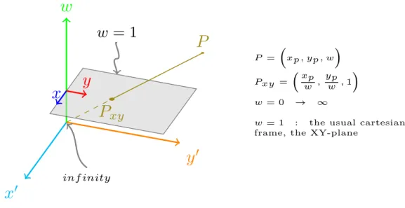
The use of homogeneous coordinates in artificial vision problems is more than an added 1-value coordinate. In fact, homogeneous coordinates are useful to describe projective transformations and to have a non-singular definition of infinity. A point in 2D space still needs three coordinates: P = (x, y) → Ph = (x′, y′, w) wherex =x′/w. From here it is easy to see that the mapping of cartesian coordinates to homogeneous ones is not unique: any value ofwcan be set; the inverse mapping, on the other hand, is unique. Whenw is zero the point is at infinity so homogeneous coordinates can in fact represent the infinity in the form of coordinates (x, y,0) instead of having to compute a zero division. In addiction, this added coordinate shows how it is impossible to go from a 2D frame into 3D, for instance, from an image frame into the world, without a complementary restriction — there are infinite possibilities (set w any value); for the reverse transformation, a projection, it shows how there are many 3D points (along a line) that project into the same 2D point (whichever the value of w, x and y are the same when the normalizationw= 1 occurs). Fig. 3.3 holds a geometric interpretation for the added dimension w.
3.2.2 Orientation of a Rigid Body: representations
There are several ways to represent the orientation (also called attitude) of a rigid body: rotation matrix (many times referred to as direct cosine matrix), euler angles, direction cosines, vector-angle representation and quaternions.
There are advantages in using some representations over the others. Rotation ma-trices are larger in size (9 elements) but their algebra is efficient and easier; nonetheless, interpolating between orientations is not possible. Euler angles are just 3 values but have discontinuities and the representation of a given attitude is not unique. Quaternion algebra is less common and more complicated but they offer means for interpolation that no other representation does.
x
′y
′w
P
xyP
x
y
w
= 1
inf inity
P = xp, yp, w
Pxy = xpw , ypw ,1
w = 0 → ∞
w = 1 : the usual cartesian frame, the XY-plane
Figure 3.3: Homogeneous Coordinates- a geometric interpretation. A pointPxy in cartesian R2 space (w= 1) can have infinite representations in homogeneous coordinates — all points along the linePxy–P. The planew= 0 represents infinity.
1. Rotation matrices use the standard matrix notation, upper-case bold letters, e.g,
R.
2. The rotation around an axis u by an angleθis denoted Ru,θ.
3. IfBRA rotates frame AtoB, then the inverse rotation ARB is defined by AR
B=
B
RA
−1
(also, R−1 =RT ) (3.3)
4. Consecutive rotations (about the current axis) are obtained by pre-multiplication of the respective matrices:
DR
A=DRCCRBBRA (3.4)
5. There are many conventions for use of the euler angles. In this thesis, euler angles were required to interface with a MOTOMAN manipulator and, as such, the convention followed is the one that best adapts to the robot programming.
around the moving axis, first there is a rotation around Z-axis by an amountφ;
then a rotation around the new Y-axis by θ; finally, there is a rotation around
the final X-axis byψ. If fixed axis are considered (extrinsic rotations), then the
order of axis rotation is reversed. MOTOMAN uses angles (Rz, Ry, Rx) but this
notation is easily confused with the matrices. Hence the adopted notation
here-after will be (φ, θ, ψ); if a rotation matrix is associated with these angles and axis,
then an orientation is described by
R=Rz,φRy,θRx,ψ (3.5)
6. Lastly, there are quaternions. These are one of the most used tools to deal
with orientations specially in the computer graphics field. Quaternions are an
extension of complex numbers in 4D space: q= [qr, qi, qj, qk]T.
7. Unit quaternions represent orientation in 3D space;q and −q represent the same
orientation whileq∗, the conjugate, represent the inverse rotation;
8. unit quaternions live on the unit sphere ofR4; interpolation between two
orienta-tions, which is not possible using rotation matrices, is simple in quaternion space
— a ”linear” interpolation on the sphere surface (called Slerp, spherical linear
interpolation).
The algorithms used in this thesis are mainly based on rotation matrices and
quater-nions. However, the interface with industrial manipulators is usually done using euler
angles or quaternions. For this reason, and to simplify the presentation of the
algo-rithms throughout the thesis, the methods for converting between each representation
are here described. Later, the representations shall be used interchangeably without
1. From euler angles to rotation matrix:
RZ,φ=
cosφ −sinφ 0 sinφ cosφ 0
0 0 1
RY,θ=
cosθ 0 sinθ
0 1 0
−sinθ 0 cosθ
RX,ψ =
1 0 0
0 cosψ −sinψ
0 sinψ cosψ
R=Rz,φRy,θRx,ψ
(3.6)
2. From axis-angle to rotation matrix — considering a rotation ofθdegrees around axisk= [kx, ky, kz]T:
Rk,θ =
k2xvθ+cθ kxkyvθ−kzsθ kxkzvθ+kysθ
kxkyvθ+kzsθ ky2vθ+cθ kykzvθ−kxsθ
kxkzvθ−kysθ kykzvθ+kxsθ kz2vθ+cθ
(3.7)
wherecθ = cosθ,sθ= sinθ and vθ= 1−cosθ.
3. From quaternion (q= [qr, qi, qj, qk]T) to rotation matrix
R=
q2
r +qi2−qj2−qk2 2qiqj−2qrqk 2qrqj+ 2qiqk 2qrqk+ 2qiqj qr2−qi2+qj2−qk2 2qjqk−2qrqi 2qiqk−2qrqj 2qrqi+ 2qjqk qr2−qi2−qj2+qk2
(3.8)
4. From rotation matrix to euler angles —considering R = [rij] and X,Y,Z angles asψ, θ, φ:
φ= atan2
r23
−qr2 11+r212
,q r33 r2
11+r122
θ= atan2
r13,
q
r211+r212
ψ= atan2
r12
−qr211+r122
,q r11 r112 +r212
(3.9)
• If Trace(R)≥0
qr= √
1 +r11+r22+r33 2
qi = sign(r32−r23)
√
1 +r11−r22−r33 2
qj = sign(r13−r31)
√
1−r11+r22−r33 2
qk = sign(r21−r12)
√
1−r11−r22+r33 2
(3.10)
• If Trace(R)<0 then pick the largest leading diagonal element. Assuming it isr11(works equivalently if is another element):
s= 2√1 +r11−r22−r33
qr =
(r32−r23)
s qi =
s
4
qj =
(r12+r21)
s
qk=
(r13+r31)
s
(3.11)
6. From quaternion to euler angles:
φ= atan22 (qrqi+qjqk),1−2
q2i +q2j
θ= arcsin (2 (qrqj+qkqi))
ψ= atan22 (qrqk+qjqj),1−2
q2j +q2k
(3.12)
7. From axis-angle to quaternion —θdegrees around axis k:
q= cosθ 2 + sin
θ
2ˆk ,with ˆk=
k
kkk (3.13)
3.3
3D computer vision
v
u
p= [up, vp] T
Figure 3.4: Image Notation- The standard frame used in image processing. Pixels are identified by their position (u, v) in the image frame/matrix.
3.3.1 Camera Model
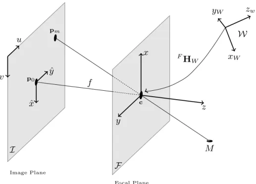
In order to understand the phenomena of capturing a scene into an image (using a camera and lenses) a model has to be established. The camerapinholemodel is arguably the most commonly used to that end. Fig. 3.5 holds a scheme from which the pinhole model can be understood and derived. It synthesizes the projection of a world point into the image frame and how the different coordinate frames are related.
The required notation:
1. M is a 3D world point and has coordinates m= [mx, my, mz]T, with respect to the world frameW={xw, yw, zw} ;
2. The corresponding pixel tomis pm = [um, vm]T;
3. The image plane I has a frame {x,ˆ yˆ} centred in p0 = [u0, v0]T ( the principal point); the usual frame for image processing (due to the matrix representation) is at the top left corner: {u, v}
5. The orthogonal distance between the planes F and I is f, the focal length; the line that connects p0 andc is the optical axis.
I Image Plane v u ˆ x ˆ y p0 pm F Focal Plane x y z c f M F
HW xW
yW zw
W
Figure 3.5: Camera Pinhole Model - The geometric relationship in a perspective projection. Thepinholemodel can be derived from this scheme (based on [58]).
The projection ofmintopm happens in two moments: first there is the transforma-tion of world coordinates into camera’s coordinates; then, the actual projectransforma-tion occurs. As for the former, it is necessary to describe the position of the camera in the world frame, i.e, specifycin terms ofW; this is accomplished by the translation vectorFt
W. The alignment of the frames, i.e,{x, y, z}matching with{xW, yW, zW}, is achieved by a rotation: FR
W. The homogeneous transformation
FH W =
" F
RW FTW
03 1
#
(3.14)
holds the so calledextrinsic parametersof the camera: how it is positioned with respect to the world.
parameters matrix
A=
α γ u0 0 β v0 0 0 1
(3.15)
which uses the principal point,[u0, v0], horizontal/vertical scale factors describing the actual size of the pixels,αand β, andγ =αcosθ – the parameter of non-orthogonality betweenu and v.
The perspective projection model, through the pinhole scheme, is then given by the projection matrixP, which takes into account both intrinsic and extrinsic param-eters. Equation 3.16 (assuming homogeneous coordinates), shows the final M → pm relationship.
pm =Pm , where P=AFHW (3.16)
3.3.2 Stereoscopy: 3D from two-view geometry
A single camera captures a world scene using an unequivocal 3D →2D mapping, i.e, world point M can be seen at pixel p and at no other; on the other hand, pixelp can be the image of an infinite set of world points: those along the line connecting optical centre c andM. This means that the image frame has no depth information.
To recover depth, at least two cameras are needed. When a world point is simulta-neously captured by two cameras(placed at distinct positions), a restriction arises that allows going from the 2D world into 3D. Fig. 3.6 shows a scheme of the stereoscopy principles. PointM appears in imageI asp and in imageI′ as p′.
The required notation:
1. The left camera image isI and the right isI′
2. The superscript ”prime” (′) indicates variables of the right camera;
3. M is a 3D world point;
M
Ω
c
c
′I
I
′Ω
b
l
l
′p
p
′e
e
′Figure 3.6: Stereoscopy- The geometric principles of two-view triangulation – known as epipolar geometry. The possible matching pixels top lie on epipolar linel′ and
6. eande′ are called the epipoles; they stand as the projection of the other camera’s centre.
7. the line b is called baseline; it connects the two centres and can be seen as the optical ray that simultaneously projects c into I′ and c′ into I. The projection pixels are the epipoles ( e/e′).
8. Lines l and l′ are called the epipolar lines. The potential matches to pixel p(or
p′) lie on epipolar linel′ (orl);
9. The plane Ω is called the epipolar plane;
Stereo is possible when both the relative positioning of the two cameras is known, and when there is a corresponding pair of pixelshp,p′i.
Epipolar geometry ([58] and [59]) provides the tools to relate cameras positioning and to generate 3D from the pixels: any corresponding pair of pixels hpi,p′ii satisfy 3.17:
p′T
i Fpi = 0 (3.17)
F is the fundamental matrix. It encapsulates both camera’s intrinsic parameters and their relative pose, i.e, the geometry relationships present on Fig. 3.6.
Finding a matched pixel pair involves image analysis with the help of epipolar geometry. Given a pixelp, the corresponding pixelp′ sits along the epipolar linel′. l′ is computed from the fundamental matrix F:
l′ =Fp p′ ∈l′⇒p′l′ = 0
∴p′Fp=0
(3.18)
So, Equation 3.17 resolves into a line equation which definesl′ given a pixelp. All the pixelsp′
i belonging tol′ are possible matches top. So, epipolar geometry gives a search constrain (a line among the entire image). Pixel features (as colour, texture, etc) must decide if the pairs match — this is called the correspondence problem.
3.3.3 Camera/Stereo Calibration
Camera calibration refers to the method of identifying/estimating the parameters of the projection matrix P – equation 3.16. A complete calibration holds the intrinsic parameters of the camera as well as its positioning according to a given world referential. Available options for calibration include (based on [58]):
1. Self-calibration: moving the camera in a rigid scenario and finding corresponding sets of points (on a least three images) provides enough data and constraints to estimate all the intrinsic and extrinsic parameters. The mathematical formulation of this problem is harder than those of the next techniques. Self calibration can be categorized as a 0D method.
2. Calibration based on a 1D line: the camera captures a set of calibration points that are displaced along a line; the points are moved around, maintaining the linear restriction; this can be achieved with a bar with a set of markers attached to it. Due to the linear restriction, this is categorized as a 1D method;
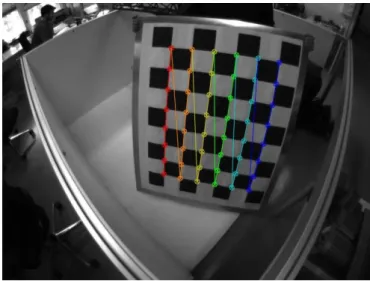
3. Calibration based on 2D patterns: this is arguably the most used method. Usu-ally, a checker-board pattern is shown to the camera – Fig. 3.7 – at different poses. The edges of the squares are found and, since the size of the real pat-tern is known, the correspondence between pixels and real coordinates enables a complete calibration of the camera’s parameters.
4. Calibration based on known 3D objects: as an upgrade to the previous method, this one relies on a 3D pattern or a 3D object whose dimensions are precisely known. The most simple form is to place two or three 2D-checker-board patterns orthogonally to each other and, again, retrieve the square corners and match them with the world coordinates.
Regarding stereo calibration, it can be achieved by using the estimated models of the cameras. If each has been previously calibrated (knownP andP′), then Fcan be computed from a closed form solution — from Hartley and Zisserman [59]:
![Figure 1.2: Industrial Robots - annual supply (taken from [1])](https://thumb-eu.123doks.com/thumbv2/123dok_br/16780374.748662/25.892.175.780.527.877/figure-industrial-robots-annual-supply-taken.webp)