Abstract— This paper describes the stages of identification, dynamic modelling and control of an unmanned aerial vehicle of type quad-rotor designed to capture images and video in high definition with relatively low cost. The identification process describes the methods used to identify the elements of the vehicle such as propellers parameters, mathematical modeling of the whole ESC-Motor-Propeller and modeling of the complete structure of the quad-rotor. PID controllers were used for the control and stabilization of the structure, controlling the rotational speed of the four motors independently. To tune the controller we have used the pole placement method, followed by simulations in MATLAB, based on the models obtained in identification. The simulations were validated with experimental measurements in prototype quad-rotor, leading to satisfactory results.
Index Terms— UAV, quad-rotor, PID controller
I. INTRODUCTION
HE UNMANNED aerial vehicles (UAVs) are increasingly gaining popularity due to the considerable technological advances in the fields of microelectronics and MEMS (Micro Electro mechanical systems ), providing a huge range of high-performance microcontrollers and sensors of several types, elements which are essential for an UAV. These technological advances also resulted in reduction of the involved costs, thereby making UAVs a technology more attractive to civilian areas and not only military, where they have already been employed in the last few decades.
The key advantages of using UAVs against conventional manned aircraft are: (i) smaller costs of production and maintenance, (ii) greater flexibility allowing to perform
Jose C. V. Junior, Julio C. De Paula, Gideon V. Leandro, Marlio C. Bonfim, are with Microelectronics Laboratory, Measurements and Instrumentation, Department of Electrical Engineering, Federal University of Paraná - PO Box 19011, Centro Politécnico, Zip Code 81531-970, Curitiba, PR, Brasil. (e-mails: [email protected], [email protected], [email protected], [email protected])
maneuvers or to move in places of difficult access to conventional aircraft, (iii) long hours of flight, (iv) in addition to eliminates any possible risks that a manned aircraft can expose to its crew.
The UAV's can be subdivided into three categories: airplanes, helicopters and airships. The standard operation of a UAV is take off, follow a route to the destination, collect information and return to the origin. The control of this operation can be done remotely from ground stations or autonomously based on flight plans previously programmed or even hybrid form using both concepts.
This paper is organized into five sections. Section II presents the stages of identification and modeling of the aircraft. Control techniques and tuning are presented in section III. Section IV describes the results obtained in the simulated environment and testing the prototype. Finally, Section V provides concluding remarks about the project developed and some considerations regarding future work to quad-rotor.
A. Selecting the type of UAV
The main objective of this research was to develop an UAV capable to capture high definition aerial images and videos in an efficient way with a relatively low cost. To fulfill this it was decided to develop an UAV of small proportions, of the type MAV (Micro Air Vehicle). Though this type of vehicle possesses a low cost, it also has an easy usability and can be easily transported and does not need a terrestrial infrastructure to perform takeoffs and landings. Another important aspect considered was the possibility of the vehicle remains still in flight, or move itself at low speeds, to ensure a good quality of captured images. For this we considered using a vehicle with vertical take-off and landing system (VTOL).
The aircraft system that was considered more viable for the project was the multi-rotors, specifically the quad-rotor. With this vehicle it is possible to obtain images at low altitudes, thereby resulting in images with high resolution and quality, which may have levels of detail far superior to the ones that are obtained by satellites or manned aircraft, with a much lower cost.
Stability Control of a Quad-Rotor Using a PID
Controller
Jose C. V. Junior, Julio C. De Paula, Gideon V. Leandro, Marlio C. Bonfim
____________________________________________________________________________
B. Quad-rotor
The quad-rotor is an aircraft derivative of helicopters because it has as main means of propulsion vertical thrust rotors. These rotors are arranged on the edges of a cross-shaped structure. The power source and the embedded elements needed to control the vehicle are located in the center of the structure. This model possesses greater mechanical simplicity compared to conventional helicopters as the locomotion depends only on the rotation speed of individual propellers. By using four rotors, propellers diameter may be smaller, reducing the kinetic energy and allowing the aircraft to reach less accessible places [1].However the quad-rotor has as main disadvantage the high power consumption which can compromise its autonomy.
This model of UAV is already has been study in several academic and commercial institutions.Among them stand out [2] that developed a prototype by using the PID control technique, embedded in an electronic system processed by a microcontroller ARM7. Another prototype was developed by [3] which uses a linear quadratic controller, embedded in an electronic system processed by an Arduino microcontroller ATmega328. In [4] a PD controller was used and in [5] the control strategy included the linearization technique of exact answer, using geometric methods of nonlinear control. There are also other studies that do not use inertial sensors integrated on the quad-rotor, such as accelerometers and gyroscopes, but visual information, such as cameras fixed on the environment and on the UAV itself, as in [6]. Still, [7] develops the control of an UAV with the help of high power leds trapped on the stems of the aircraft, along with two low-resolution cameras and working together with inertial motion sensors, joining two concepts that were presented separately .
The studies mentioned here use a more classical control technique due to a good robustness that they possess and in some cases also because the limited processing resources of electronic systems used. In this work we opted for a high performance ARM Cortex-M3 microcontroller, thus making possible the use of control techniques that may require a higher processing.
II. IDENTIFICATION
Several studies were performed in order to find a novel approach for identifying the model. In many papers as in [8] and [9] were used the dynamic model of the aircraft structure, calculating the equations of motion for pitch, roll and yaw. In our work, the identification for the mathematical model of the UAV was conducted to provide data of the prototype to the stage of simulation, in order to obtain more realistic results, thus facilitating the phase of tuning the controller. We have identified the thrust coefficient of the propellers, the mathematical model of the four motors and model of the UAV's complete structure.
The identification of some parameters was made with the aid of a test platform built throughout the project. This platform gives information on the rotation speed of the engines (using Hall-effect sensors), the thrust of the engines (using a load cell based on strain gauges) and also the electric input power. These parameters are acquired at 100 Hz sample rate and transferred to a computer for further processing and
analyses.
A. Propeller parameters
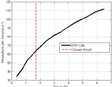
The propellers which were used in the prototype are the EPP-1045 model with a diameter of 25.1 cm. For the mathematical model used, the main propeller parameter is the thrust coefficient (CT) that relates the thrust with the rotation
speed and the propeller's diameter. This coefficient is described by equation (1) obtained in [10].
(1)
where T [N] it’s the thrust, ρ [kg m -3] the density of air, n [s-1] revolutions per second, and D [m] the diameter of the propeller. To calculate this coefficient, the propeller's thrust was measured for many different rotational speeds, whose results are shown in figure 1.
The red dashed line marked on the graph shows the thrust which each rotor should have to sustain the aircraft in realistic conditions of flight. Taking into account that the total mass of the aircraft is 700 grams (6.867 N), each of the four engines has to exercise a thrust of at least 175 grams (1.72 N) to support the weight of the aircraft. Thus the rotational speed measured at this point was 65 s-1 and CT coefficient calculated
was of 0.0798.
Figure 1. Relationship between propeller's rotation speed and thrust. B. Model ESC-Motor-Propeller
Brush-less electric motors were used in the prototype. This type of engine has a higher energy efficiency and durability compared to brushed motors. However its control system is more complex thus requiring an electronic module dedicated to this task, called ESC (Electronic Speed Controller). This module basically provides a sequence of current pulses to the motor windings to produce a rotating field. The rotational speed and electrical power given to the motor is controlled by varying the duty cycle of a PWM signal at the ESC input.
Most of the ESCs modules have a commercial 8-bit microprocessor (ATMEGA8), which performs functions of speed control of the motors and also some special functions, such as the process of braking and acceleration curve. The
resolution of the PWM modulator which performs the control of the rotation speed is around 7 bits (0.8%), with update rate of 50 Hz. During the development of this research, it was observed that this low resolution and update rate were generating instabilities in the UAV control. Thus the ESC modules were modified in order to increase the PWM resolution and update rate. The values obtained after this change resulted in a PWM resolution of 11 bits (0.05%) and a maximum update rate of 12 kHz. After this change it was possible to achieve a good stability for the UAV structure, once adjusted the coefficients of the controller.
The mathematical model of the motor is one of the most important parameters for the simulation, because it will provide key information for the dynamics of the aircraft. In this study we chose to use a template "black box", being encapsulated in the same box the ESC, the motor and propeller. This model takes as input a value of the normalized pulse width (PWM), and returns the rotation speed of the propeller. To obtain this model we used the ARX (Auto-Regressive with external input) estimation method. The ARX estimator consists of a system that uses the input and output data of the system to obtain its mathematical model in the form of a transfer function. In this case, the input signal was the PWM control signal and the rotational speed of the propeller was the output.
Thus the rotation speed was measured for the four engines with the propellers assembled, as a function of the PWM of the ESC control. Then these data were used as input and output parameters to the ARX algorithm present in Matlab. So this algorithm estimated the parameters of the transfer function for each of the four groups ESC-motor-propeller, as described in equation (2).
(2)
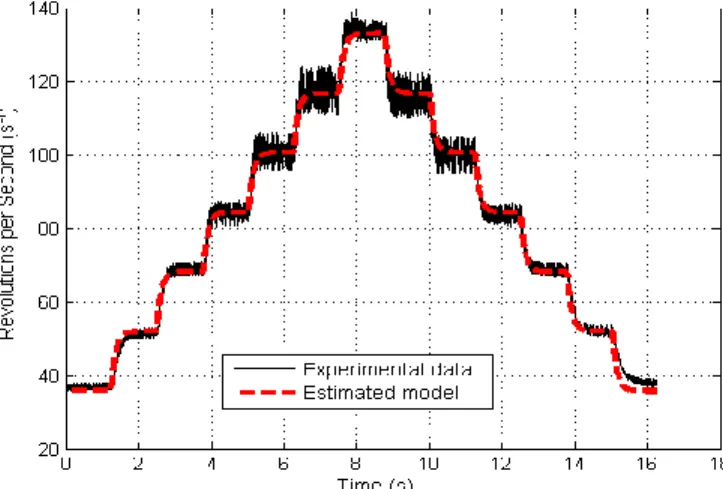
The graph in figure 2 compares actual data measured with the estimated model of one of the sets. Note that the estimated model has a dynamic behavior very close to the real system.
Figure 2. Comparison between the experimental data and the estimated model of the ensemble ESC-motor-propeller, for a staircase PWM input as a function of the time.
C. Model of the complete structure of the UAV
The identification of the complete structure of the UAV, which also was based on the black box model, uses the method of Sundaresan, which is a deterministic method that has no noise processing on it. In this case, we used an under-damped second-order system described by equation (3).
(3)
where ωn is the natural frequency of the system and ∂ is the
damping coefficient[11].
By fixing one of the rotation axis of the model (coinciding with one of the axis of the cross structure UAV), the identification was performed by collecting data from a tilt angle of the inertial sensors, which are constituted by a 3-axes accelerometer and a 3-axes gyroscope. Only two engines were active at this stage of identification. The initial condition was defined as both motors with identical rotational speeds, making the structure to maintain an angle nearly zero relative to the resting surface (ground). At the time 0.5 second it was applied a differential step in the motors speed (increased speed in one and reduced in the other) in order to lead the structure to have an angle of inclination compared to the initial condition. This angle, as well as its temporal dynamics was measured by the inertial sensors to provide data on the dynamics of the rotating structure. The tilting angle was also calibrated by a laser fixed in the structure and pointing to a wall. The signals from the inertial sensors were sampled at a rate of 200Hz, and then digitally processed using a complementary filter [12][13]. This filter can use two or more mathematical functions that complement each other, thus giving rise to the term complementary. Commonly this filter is composed of a low-pass and a high-pass filter. The low-pass filter was applied to the accelerometer, thus minimizing high frequency noise from engine vibration. The gyro signal, after integration, was applied a high-pass filter to remove its drift. The cut-off frequency of the high and low-pass filters must be the same in order to keep a flat response in the frequency range of interest. In our case, we have used a cut-off frequency of about 1 Hz, which gave us a good quality low noise, no drift tilt signal.
In order to obtain a model similar to the real one, the coefficients ωn and ∂ of equation (3) were adjusted to
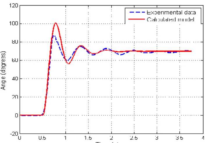
approximate the response curve for a given "delta" applied to the motor. Despite the quad-rotor's physical system nonlinearities, satisfactory results were obtained with the linear model. A comparison between the experimental data acquired by the prototype and the simulation of the calculated model is show in figure 3.
Figure 3. Comparison between experimental data (blue dashed line) and Matlab simulation of the calculated model (red continuous line), described by equation 3, in response to an excitation step.
The values found for the coefficients ωn , ∂ and for the gain
K, were equals to 11.22, 0.15 and 46.5 respectively. By placing these values in equation (3) and discretizing it with a sampling period of 5 milliseconds, it was obtained the transfer function of the system lying in equation (4).
(4)
.
III. CONTROL
The control performs a key role in the quad-rotor’s stability, making possible to control precisely the attitude and altitude states of the aircraft. It's main goal is to make the quad-rotor moves to a new desired position (called reference) and also react to external disturbances quickly and in a controlled way. Attitude control is the key element to maintain stability during flight.
In this study we used the PID controller (Proportional + Integral + Derivative). The PID controller was chosen because it is widely used in the industry on practical applications with good results, and also has an easy implementation
A. PID Controller
The structure of the controller implemented in the project may be seen in Figure 4, where y(k) represents the current state of the system sampled by the sensors, u(k) the control signal sent to actuators, that are motors, k is the current discrete time and KP, KI and KD are the gains respectively proportional, integral and derivative.
Figure 4. Block diagram of the PID controller’s structure.
Following this structure, there were implemented four independent PID controllers, one for each angle of the attitude (pitch, yaw, and roll) and one for the altitude. The diagram of
Figure 5 illustrates these four implemented controllers along with the entire system.
Figure 5. Block diagram of PID controllers implemented in the project. For the pitch angle, the controllers output modifies the speed of the front and rear motors, whereas in front its value is increased and in the rear its value is decreased. For the roll angle the controllers output modifies the speed of the left and right motors, whereas in the right its value is increased and in the left its value is decreased. For the yaw angle the controllers output modified the speed of the four motors, whereas in the front and rear its values are increased and in the right and left its values are decreased. The resulting rotation moment is due to the fact that the pitch of the front-rear propellers is opposite to the right-left propellers.
For altitude, the controllers output modifies the four motors simultaneously, being increased its values to ascend and decreased to descend the UAV.
B. Tuning the PID Controller
Tuning the controller requires knowledge of the relationship between the input and output variables of the system to be controlled. Since the UAV is a complex nonlinear system, this relationship between the input signal and the output signal is not so simple. However around some operating point, the relationship between the signals can be described by a linear model.
The literature describes several methods for tuning PID controllers such as Ziegler-Nichols; pole allocation; integral absolute error (IAE), integral of time multiplied by absolute error (ITAE), etc [14][15]. In this study the method used to tune the PID controller was the poles allocation. In this method, the set of open-loop poles are allocated in the desired closed-loop places. Thus the transient performance specifications of the system are presented in the form of desired values for performance criteria, known as constraints.
The transfer function of the closed-loop system is given by:
(5)
where: is the transfer function of the PID controller (see Figure 4) and the transfer function of the system (Equation (4)).
If the desired polynomial according to the specified control is defined by:
(6)
then, its coefficients that allocate the set of open-loop poles for the set of closed-loop poles are given by the solution of the Diophantine equation:
(7)
IV. RESULTS
The results were obtained through simulations in Matlab and experiments on the model. The simulations possessed a key role, contributing to the tuning of the PID controller in a controlled environment.
In the next stage we have validated the coefficients found for the controller through simulations on the quad-rotor. Shall be presented only the results for the control of pitch and roll movements. During these experiments, the structure of the UAV was fixed on a point located at the top of the model and in the same rotation plane of the propellers. This fixation allows the pitching and rolling movements and prevents yaw and altitude movements. During the tests, the average rotation speed of the propellers was chosen such that the structure lies in flight threshold condition, performing the necessary thrust force to compensate the weight.
A. PID Controller
The PID gains were found by the solution of Equation (7). The method for the pole allocation we have used here consists of allocating the closed-loop poles in the same radial direction of each corresponding open-loop pole, toward the origin of the plane Z. Table 1 shows the values of the gains found for the constants P, I and D.
Table 1. Gains found for the PID controller.
Controller P I D
Roll 0.0007 0.008 0.0004
Pitch 0.0007 0.008 0.0004
B. Simulation and experimental results
The results were obtained in two phases, the simulation of the calculated model in the software Matlab and experiments on the prototype. Both the simulations and the experiments, used the same reference signal or set-p oint signal, which is equivalent to performing a shift of the UAV in X and Y directions, returning to the initial position afterwards. First movement was accomplished on the X axis, or pitching movement, then in the Y axis movement or scrolling.
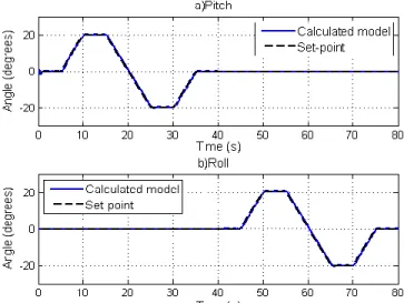
The results for the system simulation are shown in Figure 6, with the response of pitch and roll movements. The results for the prototype experiments are presented in Figure 7, again for the pitch and roll movements.
Figure 6. Matlab simulation of the identified UAV model (continuous blue line), for the pitch (a) and roll (b) movements as a function of the time, given a set-point reference (dashed black line).
It was observed that the model behavior in Matlab simulation was fast and stable, practically without delay and overshoot, both for pitch and roll responses. It's also important to note that there's no crossed influence between pitch and roll movements, which is crucial to keep the right direction of the UAV.
Figure 7. Experimental results of the UAV prototype (continuous red line), for the pitch (a) and roll (b) movements as a function of the time, given a set-point reference (dashed black line).
The behavior of the prototype (Figure 7) was very similar to the simulation, except for the quite high noise present in the angle. Despites this noise, the overall shape of the angle response follows quite well the set-point signal. As in the simulation, there's no visible crossed influence between pitch and roll movements. We are currently working on the prototype to minimize these noises.
V. CONCLUSION
In the results presented, it was possible to demonstrate the stability of the UAV using a PID controller. These results refer only to the pitch and roll movements, showing that the
identified model is, in fact, very close to reality, considering the range of rotational speeds of motors used. There are still components that were not considered for model in the identification stage, which can later be taken into account to improve the reliability.
Due to the nonlinearity present in the system, the controller cannot meet the requirements when the velocities of all motors are simultaneously increased, for example, when there is the need to gain altitude. This problem can be solved by applying an adaptive control where the component PID would work in conjunction with a fuzzy controller which, depending of the current speed of the motors, would adjust the coefficients of the PID automatically.
Sensor fusion techniques are being implemented to improve the quality of the angle measurements of the model, thereby also enabling the control of the UAV based on latitude, longitude and altitude.
References
[1] S. E. A. P. Costa, “Controle e Simulação de um Quadrirotor Convencional”, M.S. thesis, Tech. Univ. of Lisbon. Lisbon. 2008. [2] T. Bresciani, “Modelling, Identification and Control of a quad-rotor
Helicopter”, Lund Univ. Lund. 2008.
[3] J. Domingues, “quad-rotor Prototype”, M.S. thesis. Tech Univ of Lisbon, Lisbon. 2009.
[4] A. Tayebi and S. McGilvray, “Attitude Stabilization of a VTOL Quadrotor Aircraft”, IEEE Transaction on Control Systems Technology, Vol. 14, No. 3, pp. 562 – 571. 2006.
[5] A. Ahmad and D. Wang, (2008, April) “Dynamic Modeling and Nonlinear Control Strategy for an Underactuated Quad Rotor Rotorcraft”, Journal of Zhejiang Univ. (Science A), vol. 9(4), pp. 539 – 545.
[6] E. Altug, J. P. Ostrowski and C. J. Taylor, (2005). "Control of a quad-rotor helicopter using dual cameravisual feedback", The International Journal of Robotics Research, vol. 24, pp. 329-341.
[7] M. Achtelik, T. Zhang, K. KÜhnlenz and M. Buss, "Visual Tracking and Control of a Quadcopter Using a Stereo Camera System and Inertial Sensors", International Conference on Mechatronics and Automation, Changchuin, China, 2009, pp. 9 - 12.
[8] J. P. F. Guimarães, T. L. Laura, A. S. Sanca, A. N. de-Deus. M. S. Schildt, P. J. Alsina, A. T. da-Silva and A. A. D. Medeiros, “Fully Autonomous quad-rotor: A Testbed Platform for Aerial Robotics Tasks”, Brazilian Robotics Symposium and Latin American Robotics Symposium. Brazil, 2012.
[9] V. Ghadiok, J. Goldin and W. Ren, “Autonomous Indoor Aerial Gripping Using a Quadrotor”, IEEE/RSJ International Conference on Intelligent Robots and Systems, San Francisco, CA, Sept, 2011. [10] M. Hepperle, (Nov, 2011). “Aerodynamic Characteristics of Propellers”,
Available: http://www.mh-aerotools.de/airfoils/propuls3.htm.
[11] L. A. Aguirre, “Introdução à identificação de sistemas: técnicas lineares e não-lineares aplicadas a sistemas reais”, 3th ed. Belo Horizonte: Brazil, 2007, pp. 145 – 149.
[12] Mahony, Robert, Tarek Hamel, and J-M. Pflimlin. "Complementary filter design on the special orthogonal group SO (3)." Decision and
Control, 2005 and 2005 European Control Conference. CDC-ECC'05. 44th IEEE Conference on. IEEE, 2005.
[13] Euston and Mark, "A complementary filter for attitude estimation of a fixed-wing uav." Intelligent Robots and Systems, 2008. IROS 2008. IEEE/RSJ International Conference on. IEEE, 2008.
[14] D. Wang and Qing-Guo, "PID tuning for improved performance." Control Systems Technology, IEEE Transactions on 7.4, 1999. pp. 457-465.
[15] P. Cominos and N. Munro, “PID controllers: recent tuning methods and design to specification”, IEE Proceedings - Control Theory & Applications 149, 2002, pp. 46–53.
José C. Vianna Jr. received the B.S. degree in computer
engineering from Positivo University, Curitiba, Paraná, in 2011 and is currently pursuing the M. S. degree in electrical engineering from Federal University of Paraná, Curitiba, Paraná. His research interests are development in different microcontroller architectures and robotic systems.
Julio C. de Paula received M.S. degree in Electrical
Engineering from Federal University of Paraná, Curitiba, Paraná in 2012 and B.S. degree in Computer Engineering from Pontifical Catholic University of Paraná, Curitiba, Paraná in 2009. His research interests are in the fields of microelectronics, embedded electronics, control systems and robotic systems.
Marlio C. Bonfim is an associate professor at Electrical
Engineering Department of Federal University of Parana, Brazil. He received Ph.D. Degree in Physics from UJF-Grenoble-France in 2000, M.Sc. degree (1992) from UNICAMP-SP-Brazil and B.Sc. Degree (1989) from CEFET-PR-Brazil. He did a post-doctoral stage at CNRS-Grenoble-France in 2004-2005 and research stage at Elettra Sincrotone-Italy in 2011. His research interests include scientific instruments, electronic instrumentation, signal processing, microelectronics and embedded electronics.
Gideon V. Leandro is an adjunct professor at Electrical
Engineering Department of Federal University of Parana, Brazil. He received his doctoral degree in 2000 from Estadual University Campinas, Campinas, São Paulo, Brazil. He received his Master's degree in electrical engineering from Federal University of Paraíba, Campina Grande, Paraíba, Brazil in 1992 and Bachelor's degree in electrical engineering from Estadual University of São Paulo, Ilha Solteira, São Paulo, Brazil in 1989. His research interests are in the fields of control systems, system identification and discrete event systems.