DRILLING PROCESS OF COMPOSITE LAMINATES – A TOOL BASED
ANALYSIS
L. M. P. Durão1*, D. J. S. Gonçalves1, J. M. R. S. Tavares2, V. H. C. de Albuquerque2, 3, A. Torres Marques2
1
ISEP/CIDEM, Instituto Superior de Engenharia do Porto/ Centro de Investigação e Desenvolvimento em Engenharia Mecânica - R. Dr. António Bernardino de Almeida, 431 – 4200-072 PORTO,
PORTUGAL
2
FEUP/INEGI, Faculdade de Engenharia da Universidade do Porto / Instituto de Engenharia Mecânica e Gestão Industrial - R. Dr. Roberto Frias, 400 – 4200-465 PORTO, PORTUGAL 3Universidade de Fortaleza (UNIFOR), Centro de Ciências Tecnológicas (CCT), Núcleo de Pesquisas
Tecnológicas (NPT), BRASIL *lmd@eu.ipp.pt
Abstract
The distinctive characteristics of carbon fibre reinforced plastics, like low weight or high specific strength, had broadened their use to new fields. In order to join different components by using bolts, rivets or screws, one of the machining operations needed in composite structures is drilling. Usually, it is accepted that drilling can be carried out using conventional tools and machinery with adaptations. However, this operation can lead to different kind of damages being delamination the most severe as it can reduce the mechanical strength. The main mechanism responsible for delamination occurrence is the indentation caused by the drill chisel edge. It is accepted that a drilling process that reduces the thrust force exerted by the drill chisel edge during machining can decrease the risk of delamination. In this work, two combinations of the drilling process are compared: tool material – HSS, WC and PCD – and geometry – twist, Brad and step. The parameters considered for analysis include: thrust force, delamination extension open-hole strength and bearing strength. Statistical techniques are used in the evaluation. The work performed shows that a proper combination of the factors involved, like tool material, drill geometry or cutting parameters, can help to reduce the occurrence of delamination.
1 Introduction
1.1 Drilling of Composite Materials
In the 21st century, composites are one of the most promising groups of materials. Their main characteristics, as low weight and high strength to weight ratio, turn composites into an ideal selection whenever high stiffness, high strength and low weight need to be combined. The importance and employment of composite materials have been growing in latest years, which can be confirmed by their enlarged use in the new Airbus A380 or Boeing 787 airplanes. Nowadays, we can find composite materials not only in the aeronautical field, but also in other industries, like automotive, railway, energy, sporting goods, domestic appliances and so on.
Although composite parts are produced to near-net shape, finishing operations as drilling, to allow the assembly of parts, are usually required. It is accepted that these operations can be carried out with conventional tools and machining equipments with some adaptations. However, as a result of the inhomogeneity of the composites, this operation can lead to different kind of damages. The most frequent and visible evidence of damage is the existence of a damage border around the machined hole, namely at the exit side of the drill. The most referred damages that can occur, in consequence of drilling operations are delamination, fiber-pull-out and thermal damages [1]. From these damages, delamination is considered the most serious one as it can lead to a reducing of the mechanical properties of the laminate [2, 3]. Thus, it is evident that the reduction or even the elimination of this damage is of paramount importance to the industries associated to composite materials. However, this outcome has to be the result of increased knowledge of the damage mechanisms and control of the conditions that lead to its onset and propagation.
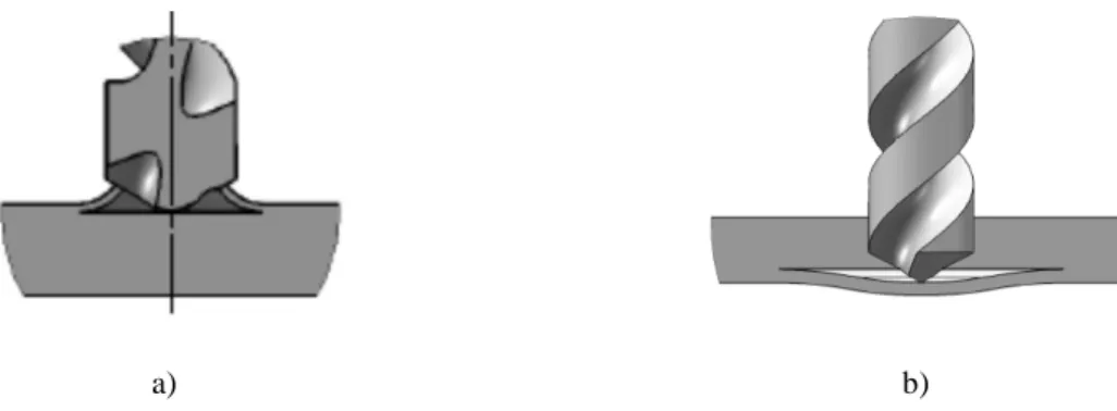
Focusing on delamination, two different mechanisms are normally referred to: peel-up and pull-out, figures 1a and 1b. The first mechanism is a consequence of the drill entrance in the upper plies of the plate and can be avoided with the use of low feeds [4]. On the other hand, the second mechanism is a result of the indentation effect caused by the quasi-stationary drill chisel edge, acting over the uncut plies of the laminate. Then, the plies tend to be pushed away from the plate, causing the separation of two adjacent plies of the laminate [5]. Finally, if the thrust force exerted by the drill exceeds the interlaminar fracture toughness of the plies, delamination takes place [4].
a) b)
Figure 1 Delamination mechanisms: a) Peel-up; b) Push-down.
The “push-down” delamination is more difficult to avoid as, at some point during the drilling process, a situation of one uncut ply will necessarily occur. Several papers had been published on the subject of delamination reduction [2, 3, 6-11]. Therefore, different analysis have been presented, such as on the effect of drill material geometry [6, 9, 10], cutting parameters [7, 8], and new drilling methods have been proposed like orbital drilling [2, 3], pilot hole drilling using two drills [11] or a specially built step drill [12] or the use of a sacrificial plate [9, 13]. Additionally, it is possible to say that delamination reduction can be accomplished as the result of a drilling process that can minimize the thrust forces exerted by the drill chisel edge [14-16].
a) b) c)
Figure 2 Drill geometries used: a) twist; b) Brad; c) step
Parameters considered for the comparison outcome include the thrust force monitoring during drilling, the assessment of delamination extension with enhanced digital radiography and an image processing platform and, finally, mechanical testing of drilled coupons for the evaluation on the mechanical properties reducing. The mechanical tests considered were the “Open hole tensile test” - ASTM D5766M-07 [17] and the “Bearing test” - ASTM D5961M-08 [18]. Additionally, statistical techniques, like analysis of variance – ANOVA – were applied to evaluate the relative importance of each experimental factor. The work here presented shows that a proper combination of the factors involved in drilling operations, like tool material, drill geometry and cutting parameters, can help on the reduction of delamination and consequently, in the enhancement of the mechanical properties of laminated plates in complex structures.
2 Materials and Methods
2.1 Composite Plates Fabrication and Drilling
To accomplish the experimental work, a batch of carbon/epoxy plates using prepreg CC160 ET 443 with a cross-ply stacking sequence and 24 layers were produced. The plates were then cured under 300 kPa pressure and 130 ºC for one hour, followed by cooling. Final plate thickness was 4 mm. Then, the plates were cut in test coupons of 165x96 mm2 for drilling experiments.
Drilling operation was carried out in a 3.7 kW DENFORD Triac Centre CNC machine. Two setup combinations were used: In the first, the twist drill geometry remains unchanged and tool material had changed from HSS to WC and then to PCD. In the second, the tool material – WC – was constant with drill geometry variation: twist drill with a point angle of 120º (Fig. 2a), a Brad drill (Fig. 2b) and step drill (Fig. 2c). All the drills had a diameter of 6 mm and the cutting parameters were, for all the tryouts, a cutting speed of 53 m/min and three feeds: 0.02, 0.06 and 0.12 mm/rev. It was already established [7, 8, 19] that an increase in feed will cause an increase both in thrust force and delamination. Nevertheless, the influence on the mechanical strength has not been confirmed yet. Details on the drills, specifically on the prototype step drill can be found in [20].
During drilling, axial thrust forces were monitored with a Kistler 9257B dynamometer associated to an amplifier and a computer for data collection. No sacrificial plates were used. The experimental setup used is shown in Figure 3.
Figure 3 Experimental setup 2.2 Delamination Evaluation
After machining completion, it was necessary to evaluate the delaminated region around the drilled hole by using enhanced digital radiography. With this purpose, plates were prior immersed in di-iodomethane for contrast for one hour. Then the radiography images were acquired using a 60 kV, 300 kHz Kodak 2100 X-Ray system associated with a Kodak RVG 5100 digital acquisition system. Figure 4a) shows an image obtained. Digital radiographies were processed by using a computational platform in order to obtain the segmentation and characterizationn of the regions of interest [21]. From the measurement procedure, the values of the damaged area, according to the delamination factor criterion proposed by Chen [22] that is defined as the ratio of the maximum delaminated diameter to the nominal hole diameter, were obtained. Figure 4a) shows an example image, the correspondent image resultant of the segmentation step figure 4b) and the diagonals measured figure 4c).
a) b) c)
Figure 4 Example of an original image a), correspondent image after the segmentation step b) and the
properties of the drilled plates. For that, test coupons of 250x36 mm2 and 1354x36 mm2 were cut and drilled under the same experimental conditions described in 2.1.
The tests were performed in a Shimadzu AG-X/100 kN Universal Testing machines equipped with the necessary accessories to run the different tests and connected to a computer for machine control and data acquisition, Figure 5.
Figure 5 Mechanical test setup: Open-hole tensile strength
3 Results and Discussion 3.1 Drill Material Comparison
Results considered for thrust force are the maximum value observed during drilling. This result is regarded as a good indication of delamination occurrence as, according to published analytical models [4], higher thrust forces normally correspond to higher delamination probability. Due to signal variation along drill rotation, thrust force values were averaged over one spindle revolution. Additionally, to reduce the influence of outlier values, the results considered were the average of six experiments done under identical conditions.
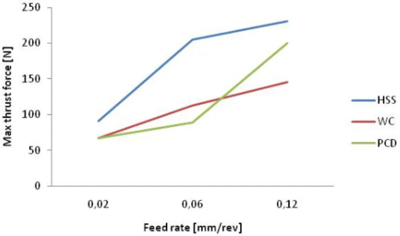
Independently of the drill geometry or material considered, the thrust force was always superior with increased feed rates, figure 6. This was an expected outcome, and it confirms previous works [7-16, 19]. Consequently, the differences are due to drill variation either in geometry or in material.
Figure 6 Correlation between feed rate and maximum thrust force
The results for the maximum thrust force, delamination factor, open hole and bearing stress tests are presented in table 1 for twist drills made on three different materials. Maximum thrust force results are the average of the three feed rates.
Drill material Max thrust force [N]
Delamination factor (Fd)
Open hole test strength [MPA] Bearing test strength [MPA] HSS 204 1.25 652 459 WC 108 1.12 602 565 PCD 118 1.15 626 529
Table 1 Results for drill material comparison
From the results presented, it is possible to say that, for twist drill geometry and under the experimental conditions of this work, tungsten carbide appears as the best material. Another attainable remark is that high speed steel drills are not recommendable for carbon/epoxy drilling. The abrasive nature of these composites is responsible for a rapid deterioration of the cutting edge, resulting in increased thrust force thus delamination. Additionally, the mechanical test results confirmed this observation. It seems that the result of the open-hole test points out an advantage on the use of HSS drills. In fact, this conclusion has to be driven in a different perspective. At section 6 of Open hole test standard method [17], is possible to realize that consistent preparation of the hole is important, as damage will affect strength results. In fact, delaminations can blunt the stress concentration due to the hole, increasing the calculated strength.
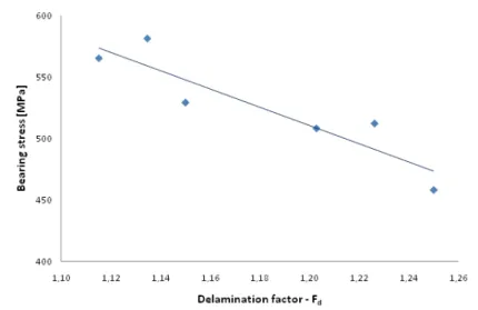
The correlation between delamination factor and maximum thrust force is presented in figure 7. From this figure, it is possible to say that larger delamination will cause a reduction in the mechanical strength of the plate around the connection region where screws, rivets or bolts are going to be used for assembly purposes.
Figure 7 Correlation between delamination factor and bearing strength 3.2 Drill Geometry Comparison
The results used in this comparison stage of the present work are in the same experimental sequence described above. As the intention was to evaluate the geometry of the drill, only one material, tungsten carbide, was used as well as only one feed rate, in this case 0.06 mm/rev. The results for the experimental sequence are presented in table 2.
Drill geometry Max thrust force [N]
Delamination factor (Fd)
Open hole test strength [MPa] Bearing test strength [MPa] Twist 113 1.13 599 556 Brad 86 1.23 597 512 Step 73 1.13 618 580
Table 2 Results for drill geometry comparison.
From the results obtained, it is evident that the drill geometry has a large influence on all parameters. The particular geometry of the step drill, dividing the drilling operation in two phases, provides a considerable reduction of the maximum thrust force. The non-chisel edge Brad drill eliminates the extrusion effect exerted by the drill tip, promoting a diverse cutting mechanism with large reduction of the thrust force. This drill is intended to tension the fibers prior to cut, enabling a clean cut. From visual inspection, holes drilled with this tool are always smoother and hole machined walls had lower surface roughness [12].
It was impossible to correlate maximum thrust force and delamination or bearing strength. The drill geometries are not equivalent and the variation due to them is too large. However, it was feasible to complete an ANOVA on maximum thrust force and delamination factor to estimate the relative influence of drill geometry and feed rate. Tables 3 and 4 present the results of this analysis on the maximum thrust force and delamination, respectively. The feed rate shows to be the most significant factor on maximum thrust force and on delamination factor. The values from the F test for the drill geometry show that this factor is also statistically significant.
Factor Level S/N SS DF V %P F 1 2 Geometry -40.27 -37.94 29 2 15 22 16 Feed rate -33.44 -39.01 104 2 52 76 57 Error 3 4 1 2 TOTAL 8 100
Table 3 ANOVA for the maximum thrust force of tungsten carbide drills
Factor Level S/N SS DF V %P F 1 2 Geometry -1.05 -2.18 2.2 2 1.1 36 11 Feed rate -0.65 -1.67 3.6 2 1.8 57 17 Error 4 10.4 7 TOTAL 8 100
Table 4 ANOVA for the delamination factor of tungsten carbide drills
4 Conclusions
Carbon fibre reinforced laminates were drilled with the objective of comparing the performance of three different tool materials and three geometries on the maximum thrust force, delamination and mechanical strength. Experimental work has involved three feed rates and one cutting speed. It is possible to draw the following conclusions from the work presented:
From the three tool materials compared, HSS should not be used in carbon/epoxy laminates drilling. The superior cost of PCD tooling may not be sufficient for replacing WC tools. Long term experiments should be performed to confirm this assumption.
Low feed rates seem appropriate for laminate drilling, as it reduces the axial thrust force and consequently, delamination. Moreover, low feeds minimize the loss of mechanical strength of the drilled part.
Tool geometry has a significant effect on all the measurements considered. Therefore, an appropriate selection of drill geometry is recommendable when drilling composite laminates. Open hole tests can easily give an indication on hole preparation, but bearing test, in spite of being more complex, should be used instead to characterize mechanical loss due to existing damage.
Acknowledgements
This work was granted by FCT - Fundação para a Ciência e a Tecnologia, Portugal, in the scope of the project “Drilling of polymeric matrix composites structures” with reference PTDC/EME-TME/66207/2006.
References
[1] Wern, C.W.; Ramulu, M., Schukla, A.: Investigation of Stresses in the Orthogonal Cutting of Fiber-Reinforced Plastics, Experimental Mechanics, 33 – 41 (1994).
[2] Persson, E., Eriksson, I., Zackrisson, L.: Effects of hole machining defects on strength and fatigue life of composite laminates, Composites A, 28, 141-151 (1997).
[3] Persson, E., Eriksson, I., Hammersberg, P.: Propagation of hole machining defects in pin-loaded composite laminates, Composites A, 31, 383-408 (1997).
[4] Hocheng, H., Dharan, C. K. H.: Delamination during drilling in composite laminates, J. of Engineering for Industry, 112, 236-239 (1990).
[5] Stuart, M.L.: International Encyclopaedia of Composites, Vol 2, 297 (1991).
[6] Piquet, R., Ferret., B., Lachaud, F., Swider, P.: Experimental analysis of drilling damage in thin carbon/epoxy plate using special drills, Composites A, 31, 1107-1115 (2000). [7] Stone, R., Krishnamurthy, K.: A Neural Network Thrust Force Controller to Minimize
Delamination During Drilling of Graphite-Epoxy Composites, Int. J. of Machine Tools & Manufacture, 36, 985-1003 (1996).
[8] Davim, J. P., Reis, P.: Drilling carbon fibre reinforced plastics manufactured by autoclave – experimental and statistical study, Materials and design, 24, 315-324 (2003).
[9] Tsao, C. C., Hocheng, H.: Effects of exit back-up on delamination in drilling composite materials using a saw drill and a core drill, Int. J. of Machine Tools & Manufacture, 45, 1261-1270 (2005).
[10] Hocheng, H., Tsao, C. C.: Effects of special drill bits on drilling-induced delamination of composite materials, Int. J. of Machine Tools & Manufacture, 46, 1403-1416 (2006). [11] Tsao, C. C.: The effect of pilot hole on delamination when core drilling composite
materials, Int. J. of Machine Tools & Manufacture, 46, 1653-1661 (2006).
[12] Gonçalves, D. J. S., Durão, L. M. P., Tavares, J. M. R. S., de Albuquerque, V. H. C., Marques, A. T.: Evaluation of Tools and Cutting Conditions on Carbon Fibre Reinforced Laminates, Materials Science Forum Vols. 638-642, 944-949 (2010).
[13] Hocheng, H., Tsao, C. C.: The path towards delamination-free drilling of composite laminates, J. Materials Processing Technology, 167, 251-264 (2005).
[14] Durão, L. M. P., Magalhães, A. G., Marques, A. T., Baptista, A. M., Figueiredo, M.: Drilling of Fibre Reinforced Plastic Laminates, Materials Science Forum Vols. 587-588 706-710 (2008).
[15] Won, M. S., Dharan, C. H. K.: Chisel edge and pilot hole effects in drilling composite laminates, Trans. of ASME J. of Manuf. Science & Engineering, 124, 242-247 (2002). [16] Tsao, C. C., Hocheng, H.: The effect of chisel length and associated pilot hole on
delamination when drilling composite materials, Int. J. of Machine Tools & Manufacture, 43, p. 1087-1092 (2003).
[17] ASTM D5766M-07: Standard test method for Open hole tensile strength of polymer matrix composite materials, ASTM International (2007).
[18] ASTM D5961M-08, Standard Test Method for Bearing Response of Polymer Matrix Composite Laminates, ASTM International (2008).
[19] Hocheng, H., Puw, Y., Yao, K. C.: Experimental aspects of drilling of some fibre-reinforced plastics, Proc. of Machining Composite Materials Symposium, ASM Materials Week, 127-138 (1992).
[20] António T. Marques, Luís M. Durão, António G. Magalhães, João Francisco Silva, João Manuel R.S. Tavares: Delamination analysis of carbon fibre reinforced laminates: evaluation of a special step drill, Composites Science & Technology, 69, 2376–2382 (2009).
[21] de Albuquerque, V. H. C., Tavares, J. M. R. S., Durão, L. M: P.: Evaluation of Delamination Damage on Composite Plates using an Artificial Neural Network for the Radiographic Image Analysis, Journal of Composite Materials, 44, 1139-1159 (2010). [22] Chen, W. C.: Some experimental investigations in the drilling of carbon fibre-reinforced
plastic (CFRP) composite laminates, Int. J. of Machine Tools and Manufacture, 37, 1097-1108 (1997).