D
RIVEABILITY
S
TUDY
F
OR
XL
O
FFSHORE
M
ONOPILE
F
OUNDATIONS
JOÃO
MARIA
FERREIRA
DE
LEMOS
FALCÃO
Dissertação submetida para satisfação parcial dos requisitos do grau de mestre
MESTRE EM ENGENHARIA CIVIL —ESPECIALIZAÇÃO EM GEOTECNIA
Orientador: Professor António Joaquim Pereira Viana Da Fonseca
Tel. +351-22-508 1901 Fax +351-22-508 1446 [email protected]
Editado por
FACULDADE DE ENGENHARIA DA UNIVERSIDADE DO PORTO Rua Dr. Roberto Frias
4200-465 PORTO Portugal Tel. +351-22-508 1400 Fax +351-22-508 1440 [email protected] http://www.fe.up.pt
Reproduções parciais deste documento serão autorizadas na condição que seja mencionado o Autor e feita referência a Mestrado Integrado em Engenharia Civil - 2015/2016 - Departamento de Engenharia Civil, Faculdade de Engenharia da Universidade do Porto, Porto, Portugal, 2016.
As opiniões e informações incluídas neste documento representam unicamente o ponto de vista do respetivo Autor, não podendo o Editor aceitar qualquer responsabilidade legal ou outra em relação a erros ou omissões que possam existir.
Aos meus Pais
The best preparation for tomorrow is doing your best today H. Jackson Brown, Jr.
ACKNOWLEDGMENTS
I would like to express my most sincere gratitude for all those who have accompanied me in this crucial part of my life. In particular, I want to acknowledge:
Professor Antonio Viana for all the support, suggestions, ideas and guidance offered during my stay in Denmark. But most of all for being responsible for the arrangement with COWI A/S which ultimately made possible, for me to embark on this exiting journey.
All the colleagues and staff at COWI A/S, for the warm welcoming. During my stay I never felt left out and felt part of the group. Thank you for the experience given on one of the leading consultant groups and for the insight delivered on new and exciting projects.
Kristine Lee Kaufmann and Ole Hededal my supervisors at COWI A/S, for all the feedback provided, interest demonstrated in the project and for being always available to help.
All of the Portuguese coworkers, for providing me a wonderful time in Copenhagen, particularly José Calejo. Thank you for receiving me so well and for all the pleasant conversations we had
To all my friends and family, who shaped me to be the person I am today.
To my parents, brothers and grandparents for all the support and care given, but most of all, thank you for the encouragement given, this work would not have been possible without your support.
ABSTRACT
Offshore monopiled foundations for wind turbines have reached a size that challenges the basis of the impact driving analysis and the empirical factored knowledge available traditionally for offshore oil and gas jacket piled foundations.
There is a need to perform an appropriate and thorough back analysis of the XL monopile foundations already installed to improve future driving predictions, and to assess if the current used methods are still adequately to use in the offshore industry.
The present work was developed in conjunction with COWI A/S. The company is a leading consultant group which is involved in several offshore windfarm projects developed in the world. COWI A/S are mainly responsible for the design of the foundations of the offshore wind turbine support structures. After an overview of the main concepts regarding driving, several methods to predict the soil resistance to driving, SRD are presented. The main methods analysed are the Alm and Hamre (2001) approach, the Imperial College Piling (2005) and the Stevens (1982) proposal. The first two methods are CPT based and consider the influence of friction fatigue, a phenomenon known to decrease the shaft resistance as the driving progresses. However, the two designs present different goals. The ICP methodology is more suitable for piles submitted to a static loading, since the piles tested were allowed to age for a period of 10 days and as such it considers set up effects. On the other hand, AH is best suited to analyse pile driveability. It is therefore difficult to clearly compare the two methods as they have different goals during the design stage. Hence, there was a need to remove the consideration of the set up effects in the ICP in order to compare it with AH and to perform an accurate driveability analysis. The method proposed by Stevens (1982) does not consider the effect of fatigue nor is CPT related.
With the CPT borehole report from an undisclosed location in the North Sea, the SRD was calculated as given by the three methods and applied to three sites. After calculating the SRD given by the literature, all of the proposals were applied on the GRLWEAP software. It was seen that the soil resistance given by the software matched the analysed methods, meaning that the software was calibrated and considers the soil resistance as seen in the literature, with all of their underlying aspects. COWI A/S provided all of the borehole reports as well as driving data, i.e. the pilling records for the piles driven in the location. Said records contain information regarding the number of blows and energy that was required to drive the pile. With the provided driving data and the calculated SRD it was possible to back calculate the required number of blows. By comparing the actual number of blows with the predict blow count from the three methods it is possible to evaluate if the methods can still be useful.
It was concluded that the CPT based methods worked fairly well when dealing with clean sands, however when facing more complex soil mixtures both AH and ICP did not prove reliable. Regarding the STV model, it was seen that it clearly underpredicts the number of blows, meaning it may be non-conservative in a driveability point of view.
Further conclusions and developments are described in the thesis itself
KEYWORDS: Pile driving, driving predictions, soil resistance to driving, GRLWEAP, blow count, friction fatigue, setup effects.
RESUMO
Neste momento as fundações de estaca offshore para turbinas eólicas chegaram a uma dimensão que desafia as bases da análise de cravação por impacto, assim como o conhecimento tradicional empírico disponível para fundações de estaca offshore
Existe uma necessidade de realizar uma análise de cravação das gigantescas estacas instaladas, com o intuito de melhorar as futuras previsões de cravação, e ainda averiguar se os métodos usados hoje em dia ainda são adequados para se utilizar na indústria offshore.
Este trabalho foi desenvolvido em conjunto com COWI A/S. A empresa é um grupo de consultoria geotecnia líder no mercado, e que esta envolvida em vários projetos offshore. A empresa é responsável pelo dimensionamento das fundações offshore que suportam as turbinas eólicas
Depois de uma consideração inicial sobre os principais conceitos relacionados com cravação, vários métodos para prever a capacidade resistente do solo durante a cravação, SRD são apresentados. Os principais modelos analisados são o método de Alm and Hamre (2001), a metodologia do Imperial College Pilling (2005) e a proposta de Stevens (1982). As primeiras duas abordagens são baseadas no CPT e consideram a influência da degradação de resistência lateral, um fenómeno conhecido por reduzir a resistência do fuste enquanto a cravação prossegue. Contudo, os dois métodos apresentam diferentes objetivos. A metodologia ICP é mais adequada para determinar a carga a medio prazo das estacas, uma vez que as estacas testadas foram permitas que envelhecessem durante 10 dias, e, portanto, o método considera efeitos de consolidação. Por outro lado, a teoria de AH é melhor aplicada para analisar a resistência aquando o final da cravação. Devido a este motivo é difícil comparar os dois métodos, pois os dois possuem objetivos diferentes durante o dimensionamento. Portanto, existe a necessidade de remover as considerações de consolidação no ICP para compara-lo com AH e para realizar uma análise de cravação explícita. O método proposto por Stevens (1982) não considera efeitos de fadiga nem é relacionado com o CPT
Com o relatório proveniente do CPT, realizado numa localização não revelada no Mar Norte, foi possível calcular o SRD nas três localizações dado pelos três métodos. Depois de calculado o SRD como visto na literatura, todos os modelos foram aplicados no software GRLWEAP onde mais uma vez o SRD foi calculado e comparado com a literatura. Foi verificado que se ajustava com os métodos analisados, o que indica que o software foi calibrado e consegue calcular a resistência do solo como na literatura, considerando todos os aspetos sobrejacentes.
Todos os relatórios CPT assim como a informação da cravação, i.e., o relatório de cravação para as estacas cravados na localização, foi fornecida pela COWI A/S. Estes, contêm informação relacionada com o número de pancadas e energia que é necessário para cravar as estacas. Com a informação de cravação e com o SRD calculado foi possível calcular o número de pancadas. Comparando o número de pancadas medido com o número previsto pelos três métodos é possível avaliar se os métodos ainda são adequados.
Foi concluído que os métodos baseados no CPT funcionavam razoavelmente bem quanto lidavam com areias limpas, para misturas de solo ambos AH e ICP não se mostraram adequados. Em relação ao modelo de STV, foi visto que claramente previa por baixo o número de pancadas, o que significa que o método não é conservativo num ponto de vista de cravação
Outras conclusões e desenvolvimentos são descritas na tese propriamente dita.
PALAVRAS-CHAVE: Pile driving, driving predictions, soil resistance to driving, GRLWEAP, blow count, friction fatigue, setup effects.
C ACKNOWLEDGMENTS ... I ABSTRACT ... III RESUMO ... V 1INTRODUCTION ... 1 PREFACE ... 1 OBJECTIVES ... 1 STRUCTURE ... 2 2PILEFOUNDATIONS ... 3 INTRO ... 3
CONSTRUCTION INSTALLATION PROCESS ... 3
MONITORING ... 3 TYPES OF PILE ... 4 2.4.1.DISPLACEMENT PILES ... 4 2.4.2.DRILLED PILES ... 6 HAMMERS ... 7 DROP HAMMERS ... 7
2.6.1.EXTERNAL COMBUSTION HAMMERS (ECH) ... 8
Air/Steam Hammer ... 8
Hydraulic Impact Hammers ... 8
2.6.2.INTERNAL COMBUSTION HAMMER (ICH) ... 8
2.6.3.OPEN ENDED DIESEL HAMMER ... 9
2.6.4.CLOSED ENDED DIESEL HAMMER ... 9
2.6.5.VIBRATORY HAMMER ... 9
ADDITIONAL EQUIPMENT ... 11
2.7.1.CUSHION ... 11
2.7.2.RAM ... 11
2.7.3.HELMET... 12
3OFFSHOREDESIGNMETHODOLOGY ... 13
INTRO ... 13
AXIAL CAPACITY ... 14
3.3.1.BROAD CONCEPTS ... 14
3.3.2.EFFECTS OF THE SOIL PLUG AND UNPLUGGED BEHAVIOUR ... 16
PILE DRIVEABILITY AND INSTALLATION ... 18
3.4.1.FRICTION FATIGUE ... 19
3.4.2.SETUP AND RELAXATION ... 20
DESIGN METHODS ... 20
ALM AND HAMRE DESIGN PROPOSAL ... 21
ICP(IMPERIAL COLLEGE PILE) DESIGN METHOD ... 24
3.7.1.SHAFT FRICTION ... 24 3.7.2.AGEING EFFECTS ... 28 3.7.3.BASE RESISTANCE ... 30 STEVENS MODEL (STV) ... 30 3.8.1.SHAFT RESISTANCE ... 31 3.8.2.BASE RESISTANCE ... 32 ADDITIONAL METHODS ... 33 3.9.1.TOOLAN AND FOX ... 33
3.9.2.API(AMERICAN PETROLEUM INSTITUTE) ... 34
3.9.3.SCHNEIDER ... 35
4WAVEEQUATIONAPPLIED TO DRIVING-GRLWEAP ... 37
INTRO... 37
DYNAMIC FORMULAS FOR STATIC CAPACITY DETERMINATION ... 37
LIMITATIONS OF DYNAMIC FORMULATIONS ... 38
ALTERNATIVES TO DYNAMIC EXPRESSIONS ... 39
FUNDAMENTALS OF WAVE EQUATION FORMULATION/APPLICATION TO DRIVING ... 39
SMITH´S MODEL ... 39
GRLWEAP ... 41
4.9.3.DRIVING ANALYSIS ... 48
GRLWEAP-SRD ... 49
4.10.1.GAIN/LOSS FACTORS ... 49
STANDARD APPROACH USING G/LFACTORS ... 50
4.11.1.VARIABLE SET-UP ... 53
FRICTION FATIGUE METHOD ... 54
5CPT AND SOILPARAMETERIZATION ... 57
CONE PENETRATING TEST ... 57
CPT INTERPRETATION ... 58
5.2.1.MEASUREMENT CORRECTIONS AND NORMALISED TIP RESISTANCE ... 58
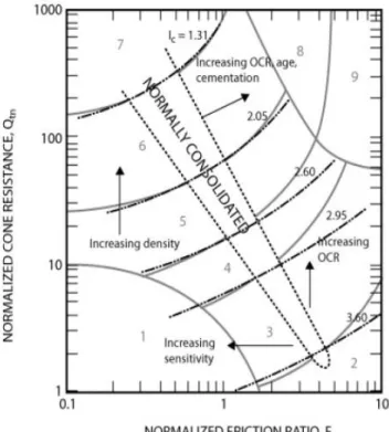
5.2.2.SOIL BEHAVIOUR TYPE ... 60
5.2.3.SOIL UNIT WEIGHT ... 61
5.2.4.FRICTION ANGLE ... 61
5.2.5.INTERFACE FRICTION ANGLE ... 61
5.2.6.RELATIVE DENSITY ... 62
COHESIVE SOIL PARAMETERS ... 63
5.3.1.UNDRAINED SHEER STRESS ... 63
5.3.2.SENSITIVITY ... 64
5.3.3.OVER CONSOLIDATION RATIO ... 64
SITECONDITIONS ... 65 6SRDCALCULATION ... 71 INTRO ... 71 PILE DESCRIPTION ... 71 ESTIMATION OF SRD ... 72 COMPARISON OF SRD ... 72 SET UP EFFECTS ... 81 GRLWEAPCALCULATIONS ... 85
6.6.1.ALM AND HAMRE (AH) ... 85
IMPERIAL COLLEGE (ICP) ... 89
STEVENS (STV) ... 92
FINAL RESULTS FOR LOCATION P02 AND P03 ... 93
7BACKANALISYS ... 95
DRIVING CONDITIONS ... 95
METHODOLOGY OF THE BACK ANALYSIS ... 95
7.3.1.SOIL MODEL ... 95
7.3.2.PILE AND HAMMER MODEL ... 97
CPT RECORDS AND SOIL CONDITIONS ... 97
BACK ANALYSIS ... 98
8CONCLUSIONS ... 105
FINISHES ... ERROR!BOOKMARK NOT DEFINED. REFERENCES ... 109
I F
Figure 2.1 - Installation procedure of bored piles, seen in Randolph and Gouvernec (2011) ... 7
Figure 2.2 - Impact Hammer, adapted from vulcanhammer.info ... 9
Figure 2.3 - ECH hammer ... 10
Figure 2.4 – Close and open ended diesel hammer ... 10
Figure 2.5 – Vibratory hammer ... 11
Figure 3.1 - Close ended pile failure Mechanism ... 15
Figure 3.2 - Open ended failure mechanism (a) Unplugged (b) Plugged, adapted from Randolph and Gouvernec (2011) ... 17
Figure 3.3 - Degradation of Friction; as seen in Heerema et al (1980) ... 20
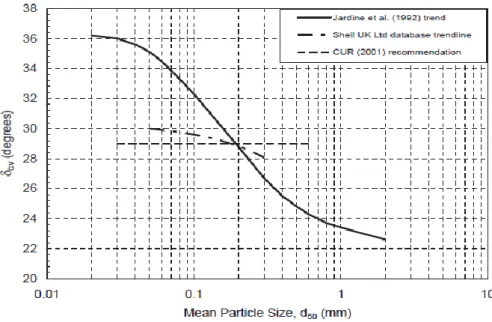
Figure 3.4 - Interface friction angle as seen in Jardine et al. (1992) ... 25
Figure 4.1 – Stress Strain diagrams, as seen in Smith (1960)... 40
Figure 4.2 – Smith´s Drivin system, adapeted from Saraiva (2014)... 40
Figure 4.3 – GRLWEAP driving system for an ECH... 42
Figure 4.4 – Dynamic Resistance Figure 4.5 – Static resistance ... 43
Figure 4.6 – GRLWEAP Bearing Graph ... 47
Figure 4.7 – GRLWEAP Inspector Graph ... 48
Figure 4.8 – Driveability graph ... 49
Figure 4.9 - Capacity vs Energy/Time for Complete Gain/Loss; as seen in GRLWEAP 2010 background ... 51
Figure 4.10 - Capacity vs Penetration or Time for Incomplete Gain/Loss ... 53
Figure 4.11 – GRLWEAP Friction Fatigue Option ... 54
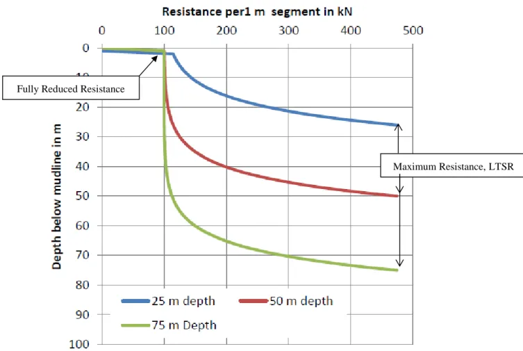
Figure 4.12 – Resistance for different penetration depths; as seen in GRLWEAP 2010 background manual ... 56
Figure 5.1 – CPTu illustration, Robertson 2015 ... 58
Figure 5.2 – Soil type behaviour; adapted from Guide to Penetration testing 2015 ... 60
Figure 5.3 – 𝐼𝑐 Table; seen in Guide to Penetration Testing 2015 ... 61
Figure 5.4 - Mean particle size ... 62
Figure 5.5 - Relative Density ... 63
Figure 5.6 - Over consolidation ratio ... 65
Figure 5.7 – Borehole report for location P01 ... 66
Figure 5.8 – CPT tip resistance; P01 ... 67
Figure 5.9 – CPT tip resistance; P02 ... 68
Figure 6.2 – Calculated unit skin friction at 22m and at 30m; AH ... 74
Figure 6.3 – Calculated unit skin friction at 22.5m and at 30m; ICP ... 75
Figure 6.4 – Rate of Degradation ... 75
Figure 6.5 – Resistance Distribution for AH and ICP respectively ... 76
Figure 6.6 – Rate of degradation for AH and ICP respectively ... 77
Figure 6.7 – Full resistance evolution for AH and ICP respectively ... 78
Figure 6.8 Increase due to setup for Ah and ICP respectively ... 79
Figure 6.9. – Logarithmic relation of pile shaft capacity with time ... 81
Figure 6.10. – Chow growth trendline ... 82
Figure 6.11 – Evolution of Qs with and without setup effects; with 𝑄𝑡 = 1𝑑𝑎𝑦𝑄𝐼𝐶𝑃 = 0.5 ... 83
Figure 6.12 – SRD comparison between AH and ICP without setup, with 𝑄𝑡 = 1𝑑𝑎𝑦𝑄𝐼𝐶𝑃 = 0.5 ... 84
Figure 6.13 Evolution of Qs with and without setup effects; with 𝑄𝑡 = 1𝑑𝑎𝑦𝑄𝐼𝐶𝑃 = 0.6667 ... 84
Figure 6.14 – SRD comparison between AH and ICP without setup, with 𝑄𝑡 = 1𝑑𝑎𝑦𝑄𝐼𝐶𝑃 = 0.6667 ... 85
Figure 6.15 – Friction fatigue factor ... 86
Figure 6.16 – Friction Fatigue Factor: Correlated ... 87
Figure 6.17. – SRD Evolution: AH ... 88
Figure 6.18. – CPT tip resistance ... 89
Figure 6.19– SRD Evolution: ICP ... 90
Figure 6.20. – CPT tip resistance ... 91
Figure 6.21– Final SRD comparison; P01 ... 92
Figure 6.22 – SRD Evolution: STV ... 93
Figure 6.23 – Final SRD results; P02 ... 94
Figure 6.24 – Final SRD results; P03 ... 94
Figure 7.1 – CPT tip resistance and soil description for Location P01; P02; P03 ... 98
Figure 7.2- Driveability for Location 01 ... 99
Figure 7.3 – Driveability for Location 02 ... 100
Figure 7.4 – Driveability for Location 03 ... 101
I T
Table 2.1– Responsibilities of design and construction engineers ... 5
Table 4.1 – Soil setup factors ... 51
Table 5.1 - Interface friction angle used by Stevens (1982) ... 62
Table 6.1 – Calculation table ... 71
Table 6.3 – SRD results ... 73
Table 6.4 – SRD comparison between AH upper bound and ICP no setup ... 91
Table 7.1 – Pile and hammer details... 96
N
Capital Latin Characters
A – Dimensionless setup factor Aann – Pile annulus area
Asup – Embedded surface area Aend – End bearing area Aplug – Plug area
D – Pile diameter
DCPT – Diameter of a CPT probe Dint – Internal pile diameter Dout – External pile diameter DR – Relative density
E – Energy Er – Rated energy F - Force
Fp – Pile capacity factor Fr – Normalized friction ratio G – Distortion modulus G/L – Gain Loss factor Ic – Index of soil behaviour J – Damping coefficient
K – Lateral earth pressure coefficient
Kc – Coefficient of radial effective stress for shaft after full equalization Kf – Coefficient of radial effective stress for shaft at failure
LLi – Limit distance
Nc - Dimensionless bearing capacity factor Nb – Number of blows
Nkt – Cone factor
Qbf – Ultimate base resistance
Qbf,p – Shear stress along the length of the soil plug Q - Normalized cone penetration resistance
QT – Capacity at time T Q0 – Reference capacity
Qtn - Normalized cone penetration resistance where the stress exponent (n) varies with soil type Qsf – Ultimate shaft resistance
Qsf,ins – Ultimate shaft friction inside the pile Qsf,out – Ultimate shaft friction outside the pile R – Pile radius
R∗ - Pile effective radius Rf – Friction ratio
Rinner – Inner pile radius Router – Outer pile radius St – Sensitivity
Su – Undrained sheer strength
Su,nom – Undrained sheer stress if normally consolidated. Pa – Reference pressure
Pa2 – Reference pressure in the same units as qc Vult – Ultimate Pile axial capacity
W – Ram weight
W′pile – Submerged weight of the pile Z – Depth
Lowercase Latin Characters
a – Net area ratio
c0 – Relative density constant c1 - Relative density constant c2 - Relative density constant
rd
fs – Setup factor 𝑓𝑠 – Sleeve friction
fs∗ – Relative pile sensitivity fsf – Unit shaft resistance fsf
̅̅̅ – Average unit shaft resistance fsf,res – Residual shaft resistance fsf,max – Maximum shaft resistance fs,o – Unit friction outside
fs,i – Unit friction inside h – Height above the pile tip k – Shape factor for degradation m - Mass
n – Damping exponent n – Stress exponent
pa – Atmospheric pressure qbf – Unit end bearing resistance
qbf,w – Unit end bearing resistance acting on the pile annulus qbf,p – Unit end bearing resistance acting on the pile plug qc – Corrected CPT tip resistance
qt – CPT tip resistance sb – set per blow t – Time
t0 – Reference time u2 – Pore water pressure v – Velocity
Greek Characters
α – Empirical adhesion factor
β – Dimensionless shaft friction for sand
Δhp – Variation of the plug length during one penetration increment
Δr – Profile of radial contraction Δlvy – Relative void index at yield
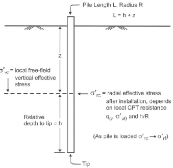
δf – Pile-soil interface friction angle at failure σ´h0 – Effective horizontal stress
σ′
v0 – Effective vertical stress σ′rf – Effective radial stress
σ′rc – Equalized effective radial stress σ´m – Mean in situ effective stress γt – Soil unit weight
γw – Submerged soil unit weight η – Hammer efficiency
Abbreviations and Acronyms
AH – Alm and Hamre
API – American Petroleum Institute CPT – Cone Penetration Test NC – Normally consolidated ICP – imperial College Pile IFR – Increment Filling Ratio
LTSR – Long Term Static Resistance OCR – Over Consolidation Ratio STV - Stevens
1
INTRODUCTION
PREFACE
The future global economy is expected to consume ever more energy, particularly with the rising energy demand of developing countries such as China and India. At the same time, the tremendous risk of climate change associated with the use of fossil fuels makes supplying this energy increasingly difficult. New ways of producing energy need to be considered in order to keep up with the development of our society and its exponential population growth of the last decades.
Use of renewable energy alternatives is therefore essential. With the present situation of increasing energy demand, rising energy prices, and global warming, renewable energy sources have taken the spotlight. Renewable energies are the ones that originate from natural processes and are replenished at a faster rate than they are consumed. In 2012, the world relied on renewable sources for around 13.2% of its total primary energy supply. In 2013 renewables accounted for almost 22% of global electricity generation and the IEA Medium-Term Renewable Energy Report 2015 foresees that share reaching at least 26% increase in 2020.
Most recently there has been an increasing interest in offshore wind farms. Wind farms are created when multiple wind turbines are placed in the same location for the purpose of generating large amounts of electric power. Due to rising energy prices and the resultant search for alternatives, there are now thousands of wind farms in many countries around the world. Along the years there has been an increase of the distance from offshore structures to the coast and the environmental conditions have become even harder. Therefore, the offshore industry was required to investigate new pile and structure solutions and new installation method techniques.
In offshore conditions, pile foundations, are commonly favoured as an alternative for shallow foundations. Usually, piled foundations are executed when there are soft soils at the surface and when high horizontal loads are present
Offshore monopiled foundations for wind turbines have reached a size that challenges the basis of the impact driving analysis and the empirical factored knowledge available tradionally for offshore oil and gas jacket piled foundations. Hence there is a need to perform an appropriate and thorough back analysis of the XL monopile foundation already installed to improve future driving predictions, which will be detailed in the present work
OBJECTIVES
COWI A/S main objective was to ascertain if the current theoretical and semi empiric methods used to predict the soil resistance to driving are still adequate to apply in the monopile foundations currently used in the North Sea. Since the methods are based on small diameter piles, when compared to the ones used in large offshore projects it is vital to understand if they can be indeed used in the large jobs seen today. In order to validate this notion, three largely used methods were chosen and applied in three different locations in the North Sea, Alm and Hamre (2001), Imperial College Pilling (2005) and Stevens (1982). Later, making use of GRLWEAP the number of blows were back calculated from the
SRD values given by the analysed design proposals. Note that the main focus of the work was on sands. The established milestones for this paper were as follows.
Assessment of soil resistance during driving using various methods, including CPT methods and those proposed by Stevens or others;
Comparison of obtained soil resistance from various methods;
Based on derived soil resistance and hammer and pile data, the driving process was modelled in GRLWEAP;
Comparison of obtained results for driving process and driving logs;
Tuning of methods for deriving soil resistance for better fit of calculated driving process to driving logs (back-calculation);
STRUCTURE
The present work is divided in 7 more sections, excluding this initial introduction chapter. Chapter 2 intents to review the used hammers in the industry as well as introducing the types of pile used. Chapter 3 gives an initial consideration on various important topics to better understand the presented work, however the main focus of the chapter is to introduce and to detail the three main methods used. Chapter 4 regards GRLWEAP and the wave equation, there the basis of the software are explained as well as other important considerations regarding energy.
In Chapter 5 the soil conditions for the analysed locations are presented as well as explanation regarding the soil parameterization using the CPT unified approach.
Finally in Chapter 6 the three methods were applied, comparison of the methods as well as the results are presented in this section. In Chapter 7 the back analysis was accomplished using the SRD results from Chapter 6. This represents the final purpose of the paper.
2
PILE
FOUNDATIONS
INTRO
Civil engineering piling structures can be divided into two main groups, onshore and offshore, although one could argue the addition of a third group: near-shore structures. What distinguishes these different structures is the area where they are located. The work presented in this paper will focus exclusively on offshore structures.
The offshore industry has been experiencing a fast development in the last few years. Due to progresses being made in the offshore driving situation, the energy industry is taking advantage of the state, and investments are being made in alternative means of energy, such as offshore windfarms. With the favourable conditions presented in the North Sea and the advantage of avoiding onshore environmental and social impacts, this industry may prove to be a lucrative endeavour.
CONSTRUCTION INSTALLATION PROCESS
Construction of a successful driven pile foundation that meets the design objectives depends on correctly relating the requirements of the static analysis methods presented on the plans to the dynamic methods of the field installation and construction control. A pile foundation must be installed to meet the design requirements for compressive, lateral, bending moments and uplift capacity. This may dictate driving piles for a required ultimate capacity or to a determined length established by the designer. In the same way, it is essential to avoid pile damage or foundation cost overruns by excessive driving. These objectives can all be successfully achieved by means of a wave equation analysis, dynamic monitoring of pile driving and by means of a static loading test.
It is clear that all pile installation restrictions should be considered during the design phase of the project, so that piles presented on the plans can be installed as designed. One example that an experienced engineer should consider is the impact that the driving and installation process have on existing structures. Further limitations on construction equipment access, size, area of operation, or environmental issues may also dictate the pile type that can be cost effectively installed.
MONITORING
Knowledgeable construction supervision and inspection are the means to a successful pile installation. State-of-the-art designs, detailed plans and other specifications must be coupled with good construction supervision to achieve desired results.
Proper pile installation is as important as rational pile design in order to obtain a cost effective and reliable foundation. Driven piles must develop the prerequisite capacity without sustaining structural damage during installation. Construction monitoring of driven piles is relatively more difficult than for spread footings, since the footing excavation and the footing construction can be visually observed to assure quality. On the other hand, piles cannot be seen after their installation, direct quality control of
the finished product is hard to achieve. As a result, a substantial control of the pile installation must be exercised in order to obtain the desired end product, meaning the required capacity.
Monitoring during construction should be followed in three distinct areas: installation equipment, pile materials, and estimation of static capacity. Understandably all of these areas are inter-laced with each other, since one change in one field will affect the others. Table 2.1 (as seen in FHWA manual Vol II 2006) provides a summarized description of all items that are to be included in the plans and specifications for quality assurance.
TYPES OF PILE
The selection of a proper pile type depends on a range of different factors, such as the type of structure, required design durability and capacity, ground conditions, among others.
There are two main groups in which pile foundations can be divided: displacement piles and drilled piles (also termed bored piles or replacement piles)
By far, the most common offshore pile is the open-ended driven steel pile, which under ideal circumstances is driven without interruptions to full penetration, except for making add-ons or when changing the hammer. Steel tubular piles provide several advantages when used in offshore conditions: they are robust, cheaper than their concrete counterparts, light to handle and capable of carrying high compressive loads, furthermore they are able to develop a high skin friction.
2.4.1. DISPLACEMENT PILES
Displacement piles are installed by "displacing" the surrounding soil. This type of pile can be either driven or jacked. During the design stage of a displacement pile, some aspects related with driveability and consolidation should be taken into attention.
Driveability concerns are related with the driving stresses, tip damage and refusal. Regarding the pile stresses, the driveability study must ensure that the pile is not overstressed and that the process of driving does not reduce the fatigue capacity of the pile material (not to be confused with the friction fatigue concept detailed in chapter 3 and 4)
If the pile tip is damaged during driving, it might experience buckle and ultimately collapse. Its common practice to execute a thickened wall near the pile tip, this solution to buckling is referred to as "shoe". In hard driving sometimes a stiffer tip is required, in such cases a welded steel plate or a conical tip is adopted. It is important to prevent pile deformation, due to damage induced by driving, as it will lead to the reduction of pile capacity or refusal.
Refusal is reached when the penetration rate is slower than 250 blows per quarter meter, once refusal is achieved it is no longer practical to drive the pile. Refusal occurs when the soil resistance exceeds the hammer capacity. This phenomenon is the driving specialist worst case scenario, however there are
Table 2.1– Responsibilities of design and construction engineers
Item Design Construction
Pile Details
Include in plans and specifications: Material and strength: concrete, steel or timber.
Cross section: diameter, tapered or straight, and wall thickness.
Special coatings for corrosion or downdrag. Splices, toe protection, etc.
Estimated pile length.
Pile design load and ultimate capacity. Allowable driving stresses.
Quality control testing or certification of materials
Soil Data
Include in plans and specifications: Subsurface profile.
Soil resistance to be overcome to reach estimated length.
Minimum pile penetration requirements. Special notes: boulders, artesian pressure, buried obstructions, time delays for embankment fills, etc.
Report major discrepancies in soil profile to the engineer
Installation
Include in plans and specifications: Method of hammer approval.
Method of determining ultimate pile capacity. Compression, tension, and lateral load test requirements (as needed) including specification for tests and the method of interpretation of test results.
Dynamic testing requirements (as needed). Limitations on vibrations, noise, head room. and fish kill
Special notes: spudding, predrilling, jetting, set-up period, etc.
Confirm that the hammer and driving system components agree with the contractor's approved submittal. Confirm that the hammer is maintained in good working order and the hammer and pile cushions are replaced regularly. Determination of the final pile length from driving resistance, estimated lengths and
subsurface conditions. Pile driving stress control. Conduct pile load tests. Ensure quality control of pile splices, coatings, alignment and driving equipment.
Unfortunately, simply increasing the hammer stroke or removing the soil plug will not always solve the refusal scenario. As such, most of the times when refusal is encountered it is necessary to waste time and money and change to a higher performance hammer.
However, it is also important to refer the impact of consolidation issues on a driven pile. Which are related to the amount of time that takes the soil to reach the full capacity once the driving process stops. This increase in resistance will understandably affect pile driveability. More on this topic will be later discussed.
2.4.2. DRILLED PILES
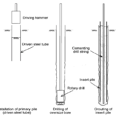
Where it is thought to be impractical to utilize driven piles, a popular alternative is the use of drilled or replacement piles. There are three basic types of replacement piles currently used in the offshore engineering.
Essentially, a borehole is drilled into the ground, then concrete is placed into the borehole to form the pile. Rotary boring techniques may allow larger diameter piles and permit pile construction through particularly dense or hard strata. Construction techniques naturally depend on the geology of the site; For end-bearing piles, drilling continues until the borehole has extended a sufficient depth (socketing) into a sufficiently strong layer. Depending on site geology, this can be a rock layer, or hardpan, or other dense, strong layers. Both the diameter of the pile and the depth of the pile are highly specific to the ground conditions, loading conditions, and nature of the project. Pile depths may vary substantially across a project if the bearing layer is not level.
Drilled piles can be tested using a variety of methods to verify the pile integrity during installation. Figure 2.1 presents visual representation. When compared to their driven counterparts, bored piles are somewhat more expensive since it requires more time, not to mention the fact that sometimes it is necessary to driven through the shallow soft soil that might exist. However there are some reasons one would use drilled piles instead of driven piles, Das (2015) lists a few:
A single drilled shaft may be used instead of a group of piles and the pile cap.
Constructing drilled shafts in deposits of dense sand and gravel is easier than driving piles. Drilled shafts may be constructed before grading operations are completed.
When piles are driven by a hammer, the ground vibration may cause damage to nearby structures.
Piles driven into clay soils may produce ground heaving and cause previously driven piles to move laterally.
There is no hammer noise during the construction of drilled shafts.
Because the base of a drilled shaft can be enlarged, it provides great resistance to the uplifting force.
Figure 2.1 - Installation procedure of bored piles, seen in Randolph and Gouvernec (2011)
HAMMERS
The hammers that are to be analysed in the present section are known as impact hammers. These machines drive the pile by first inducing a downward velocity in a metal ram. Upon impact, the ram crates a force greatly superior than its own weight, which if sufficiently large will move the pile an increment into the ground.
Currently large varieties of different hammers exist. Some are more used than others. The differences in efficiency and variable stroke options are also evident.
DROP HAMMERS
The drop hammer is the oldest type of hammer in existence. The hammer is connected to a steel cable which is attached to a winch on the crane. The hammer is then raised to the desired stroke height. The winch has a clutch on it that then allows the operator to release the hammer. The hammer will then fall and will strike the pile cap and the pile.
Drop hammers allow a good variation in both weight and speed of blows. It is also one of the cheapest hammer available with the longest service life. Furthermore, it is easy to operate.
However, it must be said, that drop hammers are currently in disuse and are only found in small to very small jobs for unimportant pilling, mainly due to its reduced efficiency.
2.6.1. EXTERNAL COMBUSTION HAMMERS (ECH)
External combustion hammers are one of the most currently used hammers in offshore conditions. ECH are hammers that make use of fuel to provide energy for the hammer´s operations outside of the hammer itself. Such hammers have external power sources, such as the crane itself, steam boilers, air compressors, or even hydraulic power packs to provide the energy to move the ram upward and in some hammers downward as well.
Two examples of ECH types will now be detailed:
Air/Steam Hammer
Air or steam hammers, as the name implies, are operated using steam or compressed air to lift the ram. At a point in the upstroke, the valve is moved and the ram floats to the top of the stroke. Following the raise of the hammer to the desired stoke level, the hammer is allowed to descend using its own weight and makes an impact on the pile. Many air/steam hammers contain a device to control the upstroke valve turnover point, thus enabling the hammer to operate at two different energy levels. This option is especially advantageous when driving and installing concreate piles.
These hammers perform well in most situations and are very reliable, usually in all soil types. Leading to a relatively low blow count, characteristic that is inherent in such hammers. Air/steam hammers have different variation, such as, single acting, double acting or differential acting.
Hydraulic Impact Hammers
Hydraulic impact hammers are somewhat recent in the offshore industry and are a new form of impacting the pile driver. One of their biggest advantage is that they are more efficient. As is the case with air/steam hammers, hydraulic hammers can be single or double acting.
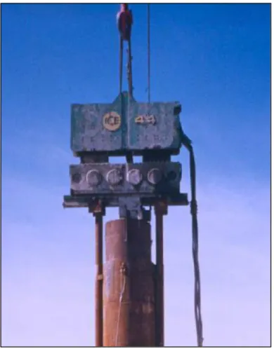
These hammers substitute the usage of air or steam for a hydraulic fluid. The hammer is applied to the piston to move the ram. Hydraulic hammers, as with its Air/steam counterpart, have several variations. Most of them employ the use of an electric valve operated with a variable timer, which allows for very flexible control. Figure 2.2 provides a schematic for an impact hammer.
Hydraulic hammers are very efficient both in power pack energy conversion and with impact force transfer. They are also useful when noise attenuation is a requirement. Yet, these hammers are expensive and are difficult to maintain.
2.6.2. INTERNAL COMBUSTION HAMMER (ICH)
These type of hammers also use fuel to power the hammer itself. The only difference is that power needed to move the hammer, takes place inside the pile. The main ICH are the diesel hammers. This type of hammers are also largely popular in the industry however, they do not see much use in Europe,
Figure 2.2 - Impact Hammer, adapted from vulcanhammer.info
2.6.3. OPEN ENDED DIESEL HAMMER
The open end diesel hammer operates as follows. The piston with the assistance of the starting device driven either from the winch of the pile driving rig or hydraulically is raised to an upper position, at which point it is released by the starting device and falls down under the effect of gravity. Before the bottom of the ram passes the bottom of the ram passes the exhaust ports, the piston will push the fuel pump lever and thus, fuel from the pump is supplied to the spherical recess of the anvil. At the bottom of the stroke, the piston impacts the anvil. The energy of impact is divided between fuel vaporization and its mixing with heated air and driving of the pile. After a relative short period of time, the air-fuel mixture is ignited and due to the pressure of the expanding exhaust gases the piston is raised up and additional driving impulse is transmitted to the pile.
2.6.4. CLOSED ENDED DIESEL HAMMER
Closed ended hammers are very similar in operating to the already described open ended diesel hammers, with the exception that a compression chamber is engaged on top of the piston to assist the ram in the down stroke. This compression chamber speeds up the blow rate of the hammer, but some of these hammers have a heavier ram relative to the energy than the open ended type. Close ended diesel hammer are usually heavy and are appropriate to use when hard driving is expected.
2.6.5. VIBRATORY HAMMER
A vibratory hammer is a machine that installs the pile into the ground by applying a rapidly alternating force to the pile, i.e. installation by means of vibration. This is generally achieved by rotating eccentric weights about shafts. Each rotating eccentric produces forces that act towards the centerline of the shaft.
Figure 2.5 – Vibratory hammer
ADDITIONAL EQUIPMENT
Driving accessories are most often required in order to achieve an easy driving process. Most of these utensils prevent any damage that might occur to the pile, while others are essential in order to actually drive the pile
2.7.1. CUSHION
Most impact hammers have some kind of cushion under the end of the ram which receives first the striking of the hammer, thus protecting the pile from the full blown impact force delivered by the hammer, preventing any damage that might had occurred. It also modulates the force-time curve of the striking impulse, and can be used to match the impedance of the hammer to the pile, thus increasing the efficiency of the blow. The actual material of the cushion and its arrangement vary, according with hammer configuration. Any hammer cushion should be installed and used in accordance with the recommendations of the hammer manufacturer. Note that pile cushion should only be used when dealing with concrete and plastic pilling, when facing with a steel made pipe, no cushion of any kind is required.
The ram is what actually impacts the pile. In a diesel hammer the initial start-up of the hammer requires the piston (ram) to be raised to a point where the trip automatically releases the piston, allowing it to fall by gravity. As the piston falls, it activates the fuel pump, which discharges a metered amount of fuel into the ball pan of the impact block. The compressed air exerts a pre-load force to hold the impact block firmly against the drive cap and pile. At the bottom of the compression stroke, the piston strikes the impact block, atomizing the fuel and starting the pile on its downward movement. In the instant after the piston strikes, the atomized fuel ignites, and the resulting explosion exerts an even greater force on the already moving pile, driving it further into the ground. The reaction of the explosion rebounding from the resistance of the pile drives the piston upward. As the piston rises, the exhaust ports open, releasing the gases and force of the explosion into the atmosphere. After the piston stops its upward movement, it again falls by gravity to start another cycle.
2.7.3. HELMET
The helmet actually mates the hammer system to the pile, and in doing so, distributes the blow from the hammer more uniformly to the head of the pile, thus minimizing pile damage
3
OFFSHORE
DESIGN
METHODOLOGY
INTRO
The design of a pile foundation must consider all aspects of the installation and performance of the system. Thus the offshore pile designer is challenged with three main tasks
Design of the pile length and section in order to satisfy bearing capacity and structural loading criteria;
Establishing the response of the pile soil system with respect to structural behaviour; The determination of a method and programme of installation;
In the project stage piles must be reliably installed to the desired depth. Also, the resulting foundation needs to have an adequate stiffness and strength to resist the design loads. The foundation should be optimised in order to minimize the number and length of the piles.
All three tasks present an interesting challenge. However, the determination of an adequate method of installation may require the greatest amount of experience and it is this step that will determine the effectiveness of the design and form a basis for the selection of pile type. One of the aspects that render this task in such a complex manner is the fact that the designer is greatly limited in the way that virtually no full scale test data exist for the size of the piles currently used in the offshore industry. Hence most of the design methods are based on small onshore pile load tests
Pile foundation differs in some aspects regarding shallow foundations. The analyses that link soil strength and foundation capacity are less rigorous and more empirical for piles. This is because the failure mechanism of a pile cannot be captured by analytical solutions. In addition, the soil properties and stress states that are considered in this analysis are often modified due to the installation process. Still, the analyses of strength and stiffness of piles, accounting for non-linear response and layering of the soil, often require numerical implementation.
One other aspect that distinguishes driven pile design and construction process is that the driving characteristics are related to pile capacity for most soils, they can be used to improve the accuracy of the pile capacity estimate. In general, the various methods of determining pile capacity from dynamic data such as driving resistance with wave equation analysis and dynamic measurements are considerably more accurate than the static analysis methods based on subsurface exploration information
Further, in pile foundations the interaction between combined loads is less significant than in a shallow foundation. Thus, the application of a horizontal load to the pile has less influence in the axial pile capacity. Also, application of a vertical load has less influence in the horizontal capacity. This occurs because the upper fewer diameters of the pile resist to the horizontal loads. On the other hand, the vertical load is carried out by the lower part of the pile.
SELECTION OF A DESIGN SAFETY FACTOR
As with all other constructions, during the design phase, it is essential to select a valid safety factor. Such factor is applied on the design load, which should be carefully chosen as a result of static analyses and consideration of the allowable stresses in the pile material. Depending on the amount of confidence in the analysis method, construction method executed and the information regarding the subsurface exploration program the safety factor may vary from 2.0 to 3.5.
In the construction stage, the ultimate pile capacity to be obtained is the sum of the design load, times the factor of safety, plus the soil resistance from unsuitable layers not counted on long term support or subject to scour. The plans and specifications should state the ultimate pile capacity to be obtained in conjunction with the construction control method to be used for determination of the ultimate pile capacity.
AXIAL CAPACITY
3.3.1. BROAD CONCEPTS
The aim of this section is to introduce the concept of axial capacity on piles as well as other underlying subjects, so that the reader has a better grasp of the methods used to estimate the driving resistance, which will be presented later on. The main focus will be on sands, hence most of the considerations will regard granular soils.
Axial strength, or axial capacity, of a pile is the maximum vertical load that a given pile can support without failing. In order to assure vertical equilibrium the axial capacity, 𝑉𝑢𝑙𝑡 must be equal to the sum of the ultimate shaft resistance (sometimes called skin resistance), 𝑄𝑠𝑓 and the ultimate base resistance, 𝑄𝑏𝑓 minus the submerged weight of the pile, which should also be supported by the soil resistance. The formulation and an illustration of this mechanism can be seen below in Equation 3.1 and Figure 3.1
Figure 3.1 represents the failure mechanism of a close ended pile. However, in open ended piles, shaft friction is observed in both the inner and the external surface of the pile wall. Thus shaft friction should be divided into two different components, the outer shaft friction, 𝑄𝑠𝑓,𝑜 and the internal shaft friction, 𝑄𝑠𝑓,𝑖.
𝑄𝑠𝑓 = 𝑄𝑠𝑓,𝑖+ 𝑄𝑠𝑓,𝑜 (3.2)
Figure 3.1 - Close ended pile failure Mechanism
Accordingly with Randolph et al (2011) the ultimate skin friction can be obtained by integrating the unit skin friction, 𝑓𝑠𝑓 over the surface of the pile. It is also advisable to divide the soil stratigraphy into several layers. Therefore, shaft friction comes as:
𝑄𝑠𝑓= 𝜋𝐷 ∫ 𝑓𝑠𝑓 𝐿
0
𝑑𝑧 (3.3)
As for the base resistance, it can be described as the maximum unit stress that can be developed on the pile base multiplied by the pile base area. For close ended piles it is formulated by multiplying the unit end bearing 𝑞𝑏𝑓 by the pile base area:
𝑄𝑏𝑓 = 𝜋𝐷2
4 𝑞𝑏𝑓 (3.4)
An important aspect that should be taken into consideration is the fact that the ultimate base resistance is mobilized after high pile settlements. In most cases this high settlement will threaten the safety of the structure that the pile is supposed to support. Due to this issue, the failure base resistance is limited to a mobilized base resistance for an allowable displacement, usually 10% of the pile diameter.
On an open ended pile, the base resistance is comprised as the sum of two components acting on the pile steel cross section, 𝑞𝑏𝑓,𝑤 and on the soil plug, 𝑞𝑏𝑓,𝑝. More details on this will be provided later on.
Empirical estimation of the unit base and shaft resistance is demanding. The soil undergoes a change of stress during driving, which is hard to predict.
Due to these underlying issues most methods predict both the skin and base unit friction based on in situ conditions prior to the pile installation.
3.3.2. EFFECTS OF THE SOIL PLUG AND UNPLUGGED BEHAVIOUR
In this topic the effect of the phenomenon known as plug will be detailed. Different failure mechanisms are possible to occur in an open ended pile. Randolph et al (2011) described them by:
Unplugged penetration (‘coring’) – the soil column within the pile remains stationary during the driving
Plug penetration – the soil column enclosed in the pile moves downwards ate the same rate as the driven pile
Partial plugging – the soil inside the pile moves down, but in a slower rate than that of the pile.
The ability to predict the soil resistance to driving as well as the axial capacity of an open ended pile is complicated by the soil plug behaviour. The relative amount of soil entering the pile can be quantified, using the incremental filing ratio (IFR).
𝐼𝐹𝑅 =𝛥ℎ𝑝 𝛥𝐿
(3.5)
Where:
𝛥ℎ𝑝– Quantifies the variation of the plug length during one penetration increment
𝛥𝐿 – Defines the variation of the pile embedded length that occurs during one penetration increment. IFR is translated as the change in plug height for an increment of penetration as compared to the length of the embedded pile. Usually when driving large diameter open ended piles the soil inside the pile tends to remain near to ground level.
An IFR of zero will correspond to a plugged penetration whereas an IFR equal to the unity corresponds to an unplugged penetration. When IFR is between zero and the unity the soil within the pile will plug partially. In order to compute the axial capacity of an open ended pile, two calculations should be made. The first should contemplate an unplugged failure and the second calculation should consider a plugged behaviour. The mechanism with the lowest resistance will govern the pile capacity behaviour.
It is now made clear that the base resistance in open ended piles depends on the degree of plug that occurs. In an unplugged penetration, the soil column within the pile does not offer resistance at the pile base. The end bearing resistance is mobilized only on the pile steel annulus
When dealing with a fully plugged penetration, the base resistance is mobilized both in the soil plug and in the pile annulus. A reduced base resistance compared to the one estimated in a close ended pile can be adopted. The following equations present the ultimate base resistance for an unplugged and for a plugged penetration. As stated in the previously paragraph 𝑞𝑏𝑓,𝑤 and 𝑞𝑏𝑓,𝑝 symbolize the unit base resistance presented by the pile annulus and the soil plug correspondingly.
Figure 3.2 - Open ended failure mechanism (a) Unplugged (b) Plugged, adapted from Randolph and Gouvernec (2011)
𝑄𝑏𝑓=
𝜋(𝐷2− 𝐷 𝑖2)
𝑄𝑏𝑓 =
𝜋(𝐷2− 𝐷𝑖2)
4 𝑞𝑏𝑓,𝑤+ 𝜋(𝐷𝑖2)
4 𝑞𝑏𝑓,𝑝 (3.7)
The formation of the soil plug is dependent on several factors, such as the pile diameter, pile length, the installation method, soil type as well as density. The arching effect is one possible effect that could explain the formation of soil plug. The compaction of the soil inside the pile will lead to a rising of the horizontal stresses and high internal shaft frictions, especially around the pile tip.
However plugging is not likely to occur during dynamic driving. Piles usually drive in an unplugged manner, the soil level inside the pile remains approximately at ground level. This is explained due to the inertia of the soil column that creates an additional component of resistance during driving, thus the unplugged penetration resistance is usually lower. However, under static loading piles usually fail in a plugged manner, with the soil level moving downwards with the pile. If plugging is to occur in driving, it is usually when the pile tip passes from a strong material into a weak. Thus, as detailed in the preceding paragraphs, the shear stress along the length of the soil plug exceeds the mobilized base resistance, as seen in Equation 3.8.
𝑄𝑠𝑓,𝑖> 𝑄𝑏𝑓,𝑝− 𝑊′𝑝𝑖𝑙𝑒 (3.8)
PILE DRIVEABILITY AND INSTALLATION
In order to achieve a correct design of a driven pile, a detailed driveability study is required. With the driveability analysis it is possible to consider the hammer energy required to drive a pile into a desired depth. Indication on whether or not refusal is encountered is also provided (refusal is achieved when the penetration rate is slower than 250 blows per quarter meter; when refusal is achieved it is no longer practical to drive the pile). With this information a hammer can now be selected and a general prediction of the expected blow counts that will be necessary to finally install the pile is also obtained. Special care should be made to ensure that the pile wall is not overstressed. It should also be mentioned the need to consider setup effects, due to temporary stops in the driving process. To summarize, the driveability study indicates the estimated number of blows and the resulting cycles of stress that will be endured by the pile during installation. The same methods used to assess the static pile strength are also used to predict the soil resistance to driving. SRD can be attained in the same way as the static pile capacity of a pile, i.e. the sum of the shaft capacity with the base resistance, the difference between the two, is that, when calculating the SRD one must consider the effects of consolidation, equalization and fatigue effects.
During installation and throughout the pile´s life many changes in the stress field occur due to the radial displacements applied to the sand. As the pile tip advances towards a given element of sand, the stress level rises significantly to push the sand radially away from the pile tip. The stress level will be comparable to the CPT tip resistance.
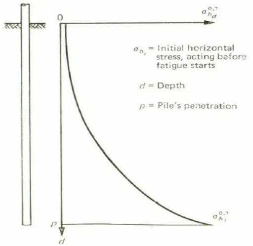
The notion of friction fatigue was first introduced by Heerema (1980). The phenomenon explained why the pile driving at Heather Filed was possible to accomplish. Soil conditions of the site consisted of a very heavily consolidated clay with an extremely high undrained sheer strength. At the time driveability prediction were mainly prepared by means of ultimate bearing capacity predictions, thus no considerations of consolidation, equalization or time effects were considered. Using axial capacity to predict the driveability pointed to an impossible task. However, the author´s research group was optimistic about the possibility of reaching the target depth, this optimism was mainly due to the consideration of the friction fatigue effect. During the driving process it was noted that although the clay´s shear strength increased with depth (leading to a supposedly progressive increase in the blow count), what occurred was that the total driving resistance increased only less-than-linearly with depth of penetration, note that if the clays sheer strength was constant the total friction should be expected to increase linearly. This reduced increase of resistance meant that the unit skin friction was lost as the pile driving continued, even though the clay´s shear strength increased. In order to better attain this concept, several tests were made. It was seen that initial friction was initially high but decreased until a certain low residual value is reached. This decrease in friction is a consequence of a horizontal soil stress decrease. Such decrease can be explained due to elastic expansion and by the vibration caused by the pile pushing the soil outwards. As installation continues, with the pile being hammered numerous times, the soil adjacent to the pile is sheared back and forth. This cyclic shearing leads to contraction of the soil. The contraction leads to the surrounding soil to relax causing a reduction in the horizontal stress acting on the pile shaft. This will form a temporary arching effect around the pile. The exponential function assumed by Heerema (1980) can be seen in Figure 3.3
As formulated, the horizontal stresses are maximum at the pile tip, and will exponentially decrease to a residual value, as penetration increases. It can also be said that friction is minimal in the area that the pile experiences the most work, i.e. shearing due to the consecutive hammer blows and is maximum in the tip where said shearing is not as high.
Currently there is no consensus as to what which is the most suitable method for assessment of friction fatigue. Some designs relate the friction fatigue to the height of a soil layer above the pile tip, Alm and Hamre (2001). Others relate the phenomenon with the normalized height with the pile diameter, such as the ICP formulation. Some methods like the one proposed by White and Lehane (2004) reinforce the notion that the primary mechanism controlling the friction fatigue is the cyclic loading that the pile suffers during installation. Despite this debate all methods agree that friction fatigue can be defined by a reduction of the maximum friction, encountered at the tip to a residual value, as the penetration increases friction will exponentially reduce. A more detailed overview and the application of this noteworthy concept will be given in the following paragraphs, in chapter 4 and in chapter 6.
Figure 3.3 - Degradation of Friction; as seen in Heerema et al (1980)
3.4.2. SETUP AND RELAXATION
Pauses in pile driving may result in a significant increase (setup) or decrease (relaxation) in the driving resistance. Generally speaking, setup is more troublesome to deal with in a driveability point of view, since the driving interruption can lead to a premature refusal. Therefore, driving schedules should be carefully planned with as few interruptions as possible, furthermore back up hammers should always be available and ready to use. More detail regarding this effect will be given along the paper.
According to Phillip Gorge in his work in offshore pile foundations, Offshore Pile Mechanics (1976) the setup occurrence may be linked to the dissipation of high water pore pressures in the thin layer of remoulded soil closely adjacent to the pile wall, which then results in an increase adhesion. This effect may be beneficial if the pile has already reached its design penetration, giving the already installed pile a higher resistance. However if the required installation depth is not yet reached the driving process will become considerably more difficult.
pile area of influence. Adding to this, the non-homogeneity of soils, along with the effects of the pile group (not discussed in this work) and pile shape hamper the understanding of soil-pile installation. Broad generalizations about pile behaviour are unrealistic and do not present accurate results. As such, an understanding of the importance of several factors involved is demanded in order to be successful in the design of pile foundations. Due to these inherent complexities, it is necessary to use practical semi-empirical methods of design and to focus attention on significant factors rather than minor or exterior loads. According to the FHWA Vol II, to achieve an optimal project, the foundation designer must have an understanding of foundations loads, subsurface conditions including soil/rock properties and behaviour, the significance of special design events, foundation performance criteria, and current practices in foundation design and construction in the area where the work is to be done. In the following paragraphs a description of the design methods analysed will be discussed.
ALM AND HAMRE DESIGN PROPOSAL
3.6.1. ALM AND HAMRE -SANDS
There has been an increasing investigation on pile diving records for the purpose of establishing updated soil models for calculation of the static soil resistance, and therefore control of blow counts in a driveability analysis. The offshore industry is designing piles with increasing diameters and penetrations in order to reach at extreme pile capacities. This ramping investigation is motivated by the continuous search for an optimum pile design in terms of a minimum cost.
In this context Alm and Hamre (1998) and Alm and Hamre (2001) developed an improved model to predict the static resistance during driving (SRD). This model is supported in dense to very dense sands from the North Sea as well as clays. The water depth at the different locations lies between 70 and 170 meters. All the piles were driven with hydraulic underwater hammers. The hammer efficiency considered was of 0.85 to 0.95. All the predictions assumed an unplugged pile failure mechanism. The proposed model takes into consideration the friction fatigue concept and is correlated to CPT (following the method update in 2001), thus minimizing additional uncertainty regarding the selection of soil parameters and modelling changes in radial stress due to pile installation.
The total driving resistance can be described as the sum of a static resistance, SRD and a damping constant. The static resistance is mobilized as a function of the pile displacement. SRD, is one of the most important variables in a driveability analyses, and is generally evaluated on basis of pile bearing capacity principles, where the capacity is contributed by pile tip resistance and side friction along the pile surface. Again, SRD is the static component, comprised by the sum of the shaft resistance with the base resistance.
𝑅𝑇 = 𝑆𝑅𝐷(1 + 𝐽 × 𝑣𝑛) (3.9)
Where:
SRD – Static Resistance to Driving (kN) 𝑣 - Pile segment velocity (m/s)
𝐽 – Damping coefficient (s/m) n - Damping exponent
As stated previously this model includes the effect of friction fatigue both in sands and in clay. The model must define a start and a residual static friction, along with a shape function describing the relative fatigue friction reduction. In other words, the shaft friction is estimated to exponentially decay from a maximum to a residual value. Further, the model for maximum skin friction is based on the Mohr Coulomb failure criteria. The formulation that this method uses is described below:
𝑓𝑠𝑓= 𝑓𝑠,𝑟𝑒𝑠+ (𝑓𝑠,𝑚𝑎𝑥− 𝑓𝑠,𝑟𝑒𝑠)𝑒−𝑘ℎ (3.10)
𝑓𝑠,𝑚𝑎𝑥 = 𝐾 × 𝜎′𝑣0tan (𝛿𝑓) (3.11)
𝑓,𝑟𝑒𝑠= 0,2 𝑓𝑠,𝑚𝑎𝑥 (3.12)
Where:
ℎ - Height above the pile tip 𝜎′0 - Effective overburden pressure
𝛿𝑓 - Soil-pile interface friction angle at failure. 𝑞𝑡 - Cone tip resistance.
𝐾 - Lateral stress coefficient 𝑘 - Shape factor of degradation
Special care should be given to the interface friction angle. It is stated that 𝛿𝑓 should be made equal to the soil friction angle minus 5 degrees. However, in section 5 an alteration to this parameter is proposed.
The lateral stress coefficient is linked to the cone tip resistance from the CPT, using the resulting formulation.
𝐾 × 𝜎′0 = 0.0132 × 𝑞𝑡× (𝜎′𝑣0⁄𝑝𝑎)0.13 (3.13)
In Alm and Hamre (2001) the shape factor for the “rate” of degradation 𝑘 was also related to the normalized cone tip resistance. It can be described as follows:
It should be noted that when using the relations established above, one must take into consideration that the formula regarding the lateral earth pressure coefficient has been established under the assumption that friction will only occur on the outside of the pile wall. Therefore, when establishing the soil friction this effect should be taken into consideration. Either by, including simply the outside friction in the calculation or by reducing the unit friction to 50% and applying to both inside and outside of the pile wall. It is true that mathematically this consideration is almost the same as stating that friction will only occur on the outside, however what is actually meant is that the distribution of friction inside and outside is not well known, hence estimating that the ratio between internal and outside friction is equal seems correct.
𝑓𝑠𝑓,𝑖𝑛𝑡⁄𝑓𝑠𝑓,𝑜𝑢𝑡= 1 (3.15)
In sands unit base resistance offered by the pile tip during driving was formulated by Alm and Hamre (2001) as follows:
𝑞𝑏𝑓,𝑤 = 0,15 × 𝑞𝑡(𝑞𝑡⁄𝜎′𝑣0)0,2 (3.16)
3.6.2. ALM AND HAMRE -CLAYS
The design proposal also makes considerations on the soil resistance when dealing with clays. However, the main focus of this paper will be on sands. Yet it is still important to describe the formulation presented by Alm and Hamre (2001) for clays. The main difference in clays concerns side friction. Initial skin friction is taken directly from the recorded CPT sleeve friction, since it was found that correlating the skin friction to CPT friction as opposed to standard pile capacity values gave the best fit. Regarding the residual friction, it was first formulated as a function of OCR and was not directly linked to CPT. Following the 2001 update on the method residual friction was found to be a function of the normalized cone tip resistance through the following formulation:
𝑓𝑠,𝑟𝑒𝑠 = 0.004 × 𝑞𝑡(1 − 0.0025 × 𝑞𝑡⁄𝜎´0) (3.17)
With increasing cone tip resistance, the residual friction was found to be slightly reduced. Unit tip resistance in clays is simply taken as 60% of the CPT tip resistance. The ultimate shaft capacity and end-bearing capacity are then calculated by the integration of the unit side friction and the unit base resistance, as stated in the beginning of this chapter:
𝑄𝑠𝑓= 𝜋D ∫ 𝑓𝑠𝑓. 𝑑𝑧 𝐿 0 (3.18) 𝑄𝑏𝑓 = 𝜋(D2− 𝐷𝑖2) 4 𝑞𝑏,𝑓,𝑤 (3.19)