INTRODUCTION
Silicon carbide (SiC) is a non-oxide ceramic material that has attractive properties, such as high-temperature hardness, wear resistance, specific stiffness, relatively low weight, corrosion and erosion resistance, low thermal expansion coefficient as well as high thermal conductivity. It has found interesting commercial applications, e.g. abrasives, cutting application, diesel engine parts, structural materials for a nuclear reactor, and electronic devices [1-6]. Anyway, its natural availability is very limited, so that, to date, SiC for the market is synthetically produced. Edward G. Acheson (1893) using his own furnace synthesized silicon carbide crystals, during some tests to produce diamond-like crystals
A novel thermal plasma-based technology for submicronic silicon
carbide production at pilot scale
(Nova tecnologia baseada em plasma térmico para produção de carbeto de
silício submicrométrico em escala piloto)
C. Freda1*, G. Cornacchia1, A. Donatelli2, M. Corrado1, M. Martino1,
A. De Girolamo Del Mauro3, S. Galvagno3
1ENEA Research Centre, Laboratory of Thermochemical Processes for Wastes and Biomass Valorization,
SS. Jonica 106 km 419+500, 75026 Rotondella, MT, Italy
2ENEA Research Centre, Laboratory of Functional Materials and Technologies for Sustainable Applications,
SS. Appia km 706.00, 72100 Brindisi, Italy
3ENEA Research Centre, Laboratory of Nanomaterials and Devices, Piazzale Enrico Fermi, 1,
80055 Portici, NA, Italy
https://orcid.org/0000-0002-8048-1937
Abstract
Submicronic powder of silicon carbide was synthesized in a pilot novel radiofrequency plasma torch reactor. The precursors were pyrolysis char and silica powders both with micrometric size. The mass rate of the precursor powder varied in the range 600-2500 g/h. The maximum test time was approximately 3 h. With the goal to increase the process yield, several technical measures were implemented. Silicon carbide yield was above 70 wt% when the plasma flame was confined by a tube that prolonged the residence time of the reactants at the useful temperature for the advancement of reaction. The silicon carbide was characterized by XRD, SEM, and DLS. Both α and β-crystalline phases were detected.
Keywords: SiC, plasma torch, gas phase synthesis, grain size, char.
Resumo
Pó submicrométrico de carboneto de silício foi sintetizado em um novo reator piloto de tocha a plasma por radiofrequência. Os precursores foram pós de cinza de pirólise e sílica com tamanhos micrométricos. A taxa de massa do pó de precursor variou na faixa de 600-2500 g/h. O tempo máximo do teste foi de aproximadamente 3 h. Com o objetivo de aumentar o rendimento do processo, várias medidas técnicas foram implementadas. O rendimento de carbeto de silício foi superior a 70% quando a chama de plasma foi confinada por um tubo que prolongou o tempo de residência dos reagentes à temperatura útil para o avanço da reação. O carbeto de silício foi caracterizado por DRX, MEV e DLS. Ambas as fases cristalinas α e β foram detectadas.
Palavras-chave: SiC, tocha de plasma, síntese de fase gasosa, tamanho de grão, cinza.
by milling of Acheson SiC products is not successful [11]. Special attention was given in recent years towards the synthesis of ultrafine SiC powder and SiC composites to allow the production of high-performance products [12-16]. Particularly, plasma techniques have been attractive for this purpose by virtue of the high energy available and the short reaction time required.
Nano-SiC powder with a mean particle size between 10 and 500 nm was obtained using a thermal plasma [17]. Micro-silicon carbide was synthesized by mixing and then calcining a silicon fine powder having a diameter less than 100 μm and as carbon source graphite or carbon black. The product was treated in a plasma torch to obtain the ultrafine SiC powder. The plasma torch physically works reducing the size of the micrometric SiC to nanometric one. Probably, an evaporation of micrometric SiC is followed by a rapid quenching of the gaseous SiC to freeze the size of the SiC to nanometric dimension. Submicronic silicon carbide synthesis was obtained in plasma torch using precursors in liquid or gaseous phase; liquids are easily volatilized by the plasma energy and the silicon carbide reaction occurs in the gas phase. Liquid methyltrichlorosilane and methylchlorodisilanes were injected into a radiofrequency plasma torch of 50 kW to synthesize submicronic SiC [18]. SiC nanoparticles having a dimension less than 100 nm was obtained through a DC plasma torch of about 10 kW using a liquid volatile precursor (silicon tetrachloride) and a gaseous one (methane). The powder was dominated by β-SiC including some of α-SiC and free carbon species. The conversion to SiC was mainly affected by the addition of hydrogen gas because it promoted the decomposition and reduction of SiCl4. Further, the conversion was varied
with process conditions such as the molar ratio of H/Si and C/Si. The powder collected at the vessel and filter, compared to the reaction tube, was richer in SiC. The average size of the powder synthesized was estimated to be below 100 nm and uniform in distribution [19]. Rhee et al. [20] patented a synthesis system for silicon carbide nanopowder. They used as a precursor a liquid compound containing silicon and carbon that was carried by a gas in a synthesis vessel where a plasma was confined. A cooling gas system was used to quench the surface of the nanoparticles during the synthesis process of silicon carbide nanopowder [20]. Keun et al. [21] filed a patent which deals with the synthesis of fine silicon carbide powders in a plasma jet reactor using methyldichlorosilane as a precursor. The SiC synthesis by plasma torch was tested using precursors at solid state, too. In fact, SiC powder was synthesized from elemental silicon and methane using induction plasma technology. The purest SiC powder was collected in the metallic filter. It was composed of both α- and β-phase of SiC with small levels of free silicon and carbon. The reaction route used is based on the evaporation of the injected pure silicon starting powder, followed by carburization of the silicon vapor using methane. Using silicon powder with a mean particle diameter of 100 μm, at a plasma power of 43 kW, the conversion of silicon to SiC in the product powder was 44%. The silicon feed rate
was 4 g.min-1, and the C/Si molar ratio was 0.7. Using silicon
particles with a mean diameter of 45 μm, the conversion of silicon to SiC increased to 70 wt%, under the same plasma operating conditions and powder feed rates [22]. Károly et al. [23] used a commercial silica powder and various types of carbon source as solid precursor mixtures. They were fed to a 25 kW RF laboratory scale plasma torch with a mass rate of about 50 g/h. The best process performance was observed by using pyrolysis char and when a slight carbon excess compared to silica was experimented [23].
In the present work, the experimental results of synthesis of submicronic silicon carbide by a radiofrequency plasma torch having a nominal power of 150 kW are presented. Compared to the literature, the precursors of the SiC used in this research are low-cost solids (silica and pyrolysis char powder), a higher precursor mixture mass rate was investigated (600-2500 g/h) in a pilot plant and novel architectonic measures were introduced in the reactor that together with fine-tuning of the experimental parameters gave a yield of submicronic silicon carbide interesting for the next exploitation of the technology at industrial scale.
EXPERIMENTAL PROCEDURE
Materials and characterization: the precursors used were
commercial silica provided by Sibelco and pyrolysis char produced from granulated waste tires in a pilot-scale rotary kiln pyrolizer at 800 °C. The pyrolysis char was milled in a Retsch Vibratory Disc Mill RS 200 at 1200 rpm for 1 min, then the char powder was sieved at 300 μm. The particle size distribution of the precursors was measured by laser diffraction by using a Mastersizer E Malvern instrument. The mean particle size of SiO2 particles was 6 μm, while the mean
particle size of char particles was 48 μm. Char powder and silica sand were mixed to obtain two mixtures having char powder content equal to 50 and 57 wt%, respectively. The carbon to silica molar ratio in both mixtures was higher with respect to the stoichiometric ratio of reaction A, with the goal of converting as more as possible the SiO2 (Table I), because
SiO2 removal is environmentally inadvisable with respect to
the char removal. The powder was ground and homogenized in the disk mill, at 700 rpm for 30 s. Both homogenized mixtures had a mean diameter of about 10 μm. For an example, in Fig. 1 the particle size distribution of the mixture at C/SiO2=1.3 wt/wt is shown. The mixtures were stored for
12 h in an oven at 120 °C to dry the mixture. Identification of the crystalline phases of SiC was performed by the X-ray diffraction (XRD) method by mean of a Philips X’Pert-MPD using nickel-filter and CuKα radiation in the range of 2θ= 20-80°. Morphological analysis of the SiC powder was carried out with a FEI scanning electron microscope equipped with a filament of tungsten, at 30 kV, and working under high vacuum conditions. The size distribution of particle suspensions was measured using a dynamic light scattering (DLS) with a Malvern Zetasizer Nano ZS.
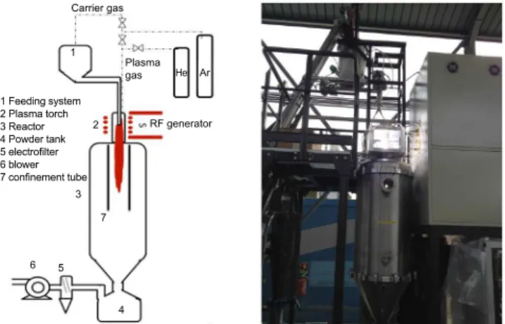
Plasma torch reactor: the plasma torch plant for the
SiC synthesis is shown in Fig. 2. The feeding system of the precursor powder consists of 10 L hopper and a feeding screw. A vibrator shakes the hopper when the powder has a cohesive and adhesive behavior that hinder correct feeding. A carrier gas (Ar) purges the feeding system. The powder gets into the plasma torch axially or radially to plasma flame. Axial inlet occurs by a stainless-steel water-cooled probe. Radial inlet occurs by two nozzles positioned below the plasma torch. The plasma torch was provided by Plasma Microsystem. It is a RF induction torch mounted on the top of the reactor having a nominal power of 150 kW. It is equipped with a water-cooling system. A water-cooling copper coil wraps the quartz torch tube and it is connected to a radiofrequency generator of 2 MHz. The plasma gas (Ar, He) gets from the top of the torch through a swirling diffusion plate. Helium was used to increase the energy of the plasma. In fact, it is known that the electron temperature in an atmospheric helium plasma is approximately twice as high as than in an argon plasma operated at the same conditions [24]. The stainless-steel reactor is cooled by water that flows in a shell to avoid the melting by the high plasma temperature. Moreover, the cooled walls of the reactor hinder the silicon carbide grain growth. Downstream of the reactor a tank for powder collecting, an electrofilter for fine powder and a suction blower are installed. With the goal of increasing the yield of the process, some novel technical measures were adopted as concerns the architecture of the reactor: a tube was introduced under the plasma torch to confine the plasma
flame. Its dimensions and material are crucial variables because of the high temperatures of the plasma, high thermal shock at the start-up and thermal dilatation [25]. An isostatic graphite tube, provided by Mersen company, was chosen because of its high melting temperature of 3500 °C and its thermo-chemical stability to the plasma process gas. The confinement tube could be lifted in the reactor by means of a mechanical system. Moreover, it was externally covered by an alumina shell to prevent thermal energy dissipation. Two thermocouples measured the wall external temperature at the top and bottom of the tube.
Method: the dry precursor mixture was loaded to the
hopper of the feeding system. The volumetric rates of carrier gas (argon) and plasma gas (argon/helium) were set to the test condition. The water cooling of the reactor and of the plasma torch was switched on to avoid that thermal energy could damage the system. The plasma torch was usually ignited at 9 A and 6 kV. After that, the suction blower was switched on, the power was tuned to the test value and the feeding of the precursor mixture started. The tests were stopped by switching off the precursor powder feeding and by a soft reduction of plasma volumetric rate up to the plasma flame was shut down. After that, the blower was stopped. The plant was fluxed with a minimum volumetric rate of argon, about 5 NL/min for about 3 h until the reactor temperature was at 30-40 °C. At this temperature the water-cooling systems were switched off, the reactor was disassembled and the product powder was collected. It was composed of unreacted carbon and silica, and silicon carbide. Organic carbon was burnt in a muffle at 700 °C for 1 h, as in Eq. B:
C + SiO2 + SiC + O2 = CO2(g)↑ + SiO2 + SiC (B)
The SiO2 was removed by leaching the powder with an
excess of hydrogen fluoride solution at 39.5%, as in Eq. C [26]:
SiO2 + SiC + 6HF = H2SiF6(g)↑ + SiC + 2H2O (C)
Table I - Experimental and theoretical molar relationships using excess char powder (Eq. A).
[Tabela I - Relações molares experimental e teórica usando excesso de pó de cinza (Eq. A).]
SiO2 3C SiC 2CO
In (mol) a b
Out experimental (mol) a-x b-3x x 2x
Out theoretical (mol) - b-3a a 2a
Figure 2: Layout of the plasma torch plant (a), and a photo of the running plant (b).
[Figura 2: Layout da planta de tocha a plasma (a) e foto da planta em operação (b).]
1 Feeding system 2 Plasma torch 3 Reactor 4 Powder tank
5 electrofilter
6 blower
7 confinement tube
Carrier gas
Plasma gas
RF generator 1
2
7 3
5 6
4
Ar
Figure 1: Particle size distribution curves of SiO2, char, and
homogenized mixture at C/SiO2=1.3 wt/wt.
[Figura 1: Curvas de distribuição de tamanho de partícula de
SiO2, cinza e mistura homogeneizada com C/SiO2=1,3 m/m.]
12
10
8
4 6
Fraction (wt%)
Particle diameter (µm)
2
0
0.1 1 10 100 1000
After having established that SiC was formed in the plasma torch reactor, the yield was calculated, as it is a parameter to assess the performance of the process. As written above, SiO2
is the limiting reactant as in reaction A results that ‘b>3a’ (Table I). Therefore, the maximum number of producible moles of SiC is equal to ‘a’. Conversely, the experimental SiC moles is ‘x’. The yield is defined as the percentage ratio between the experimentally produced moles of SiC (x) and the theoretical producible moles of SiC (a) given by:
Yield SiC = .100 (D)
RESULTS AND DISCUSSION
In a plasma torch reactor, the synthesis of SiC from solid precursors such as char and silica requires the vaporization of the small particles and their reaction in the gas phase. Quartz silica sand has a boiling point at 2230 °C. The transition of char from solid to gaseous phase occurs in a wide range of temperature, as it mainly shows an amorphous carbon skeleton structure where metallic elements and heteroatoms such as oxygen and hydrogen are present. Therefore, the plasma flame should provide thermal energy to the precursors for their phase transition and to form covalent bonds silicon-carbon [23]. The submicronic size of the silicon carbide grains is obtained hindering crystal growth by quenching the crystalline germs [27]. It occurs both when crystalline germs adhere to the water-cooled wall of the reactor and when they are elutriated by the gas towards cold plant zones such as the tank or downstream piping. The plasma torch reactor showed some critical issues. Particularly, the plasma flame stability was not excellent, external discharge of the plasma occurred at a hard-experimental condition, i.e. when plasma power was higher than 100 kW when air humidity was high, or during long-running test. Analogously, the cooling system of the torch and of the reactor was not enough to preserve the material integrity when the power was higher than 100 kW. Thence the correct running of the plant was mastered by a fine-tuning of the experimental condition and by improvement to the cooling system. It is known from the
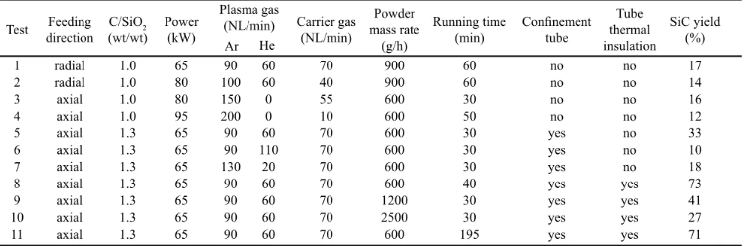
literature that the success for the operation of a RF plasma torch depends to a large extent upon the ability to sustain a stable plasma, in particular, when reagents are being injected. The injection of reagents, particularly solids, into the plasma results in turbulence and rapid cooling when the feeding rate is relatively high [28, 29]. In Table II the synthesis tests of silicon carbide in the plasma torch reactor are summarized.
The precursor powders were fed to the plasma flame by an axial probe or by two opposite nozzles radial to the flame direction. Each feeding direction had its advantages and drawbacks. The axial feeding occurred in the middle of the plasma flame, therefore the powder had a higher residence time in the plasma flame compared to the radial feeding that occurred below the torch. The accurate residence time calculation of the powder in the plasma flame requires a knowledge of the plasma temperature field and the motion field of the powder in the plasma flame. Anyway, a rough estimation was calculated for the axial and orthogonal feeding by assuming that: the plasma flame has a cylindrical shape with a diameter equal to the torch (90 mm); the plasma flame length is 40 cm (visual inspection from a manhole); the average plasma temperature is 2000 °C; the powder is correctly injected in the flame and crosses the flame following the gas direction. It was considered a total (carrier+plasma) gas rate of 220 NL/min and that the orthogonal feeding occurred 20 cm below the axial feeding. From a simple calculation, it can be stated that in the case of axial feeding the residence time of the powder was about 70 ms, instead of in orthogonal feeding that was about 30 ms. Axial feeding caused the fouling of the torch quartz tube with the precursor and/or produced a powder. In radial feeding a correct carrier gas rate should be used to give to the feeding mixture the kinetic energy necessary to gets into the plasma flame [30]. However, even with the best control, a spraying efficiency higher than 40 wt% of the fed powder is rarely obtained for radial feeding [31, 32]. On the base of their experience, the authors of the present work advice an axial feeding of the precursor mixture by a water-cooled probe, in the middle of the plasma flame, coupled with a system to reduce the fouling of the torch.
Test directionFeeding C/SiO2
(wt/wt) Power (kW)
Plasma gas
(NL/min) Carrier gas
(NL/min)
Powder
mass rate
(g/h)
Running time
(min) Confinement tube
Tube thermal insulation
SiC yield (%)
Ar He
1 radial 1.0 65 90 60 70 900 60 no no 17
2 radial 1.0 80 100 60 40 900 60 no no 14
3 axial 1.0 80 150 0 55 600 30 no no 16
4 axial 1.0 95 200 0 10 600 50 no no 12
5 axial 1.3 65 90 60 70 600 30 yes no 33
6 axial 1.3 65 90 110 70 600 30 yes no 10
7 axial 1.3 65 130 20 70 600 30 yes no 18
8 axial 1.3 65 90 60 70 600 40 yes yes 73
9 axial 1.3 65 90 60 70 1200 30 yes yes 41
10 axial 1.3 65 90 60 70 2500 30 yes yes 27
11 axial 1.3 65 90 60 70 600 195 yes yes 71
Table II - Data of SiC tests in plasma torch reactor.
From a thermodynamic point of view when the C/SiO2
ratio in the mixture increases, the equilibrium of the reaction A shifts towards the silicon carbide production. From Table II the higher SiC yields were observed at higher C/SiO2 ratio and
by using synergic measures in the management of the plant. In tests 1-4, the plasma torch power was increased from 65 to 95 kW. This means that higher energy was available for the synthesis of the silicon carbide. In fact, in test 1 the specific energy for the synthesis was 72 kWh/kg while in test 4 it was 158 kWh/kg. Despite the power increase, in tests 1-4 the SiC yield did not show an increasing trend. Furthermore, the yields were below 20%; these values, even if are encouraging, should be duly kept in the account before an eventual industrial exploitation of the process at these experimental conditions. From a visual inspection of the reactor after the tests, it was observed that a powder film covered the wall of the reactor whose thickness was proportional to the running time and to the mass feeding rate of the tests. Probably, during the process, the precursor powder very quickly escapes from the hot plasma flame towards the cold wall of the reactor pushed by the thermal gradient between the plasma flame and the cold wall of the reactor. Therefore, the powder has not the necessary residence times for carbon and SiO2 transition
from solid to gas phase and SiC synthesis with high yield. In fact, from a deep thermodynamic analysis, Karoly et al. [23] showed that the governing reaction of SiC formation under 2700 °C can be described as Si(g)+C(s,g)→SiC(s), with the minor
participation of C(s).
From test 5 to 11, the synthesis tests were carried out with the graphite tube allocated under the plasma torch. The tube confines the bottom of the flame coming out of the torch. In this way, the energy available for the process increases because the flame is less affected by the reactor cooling system. Furthermore, the powder escaping is limited and it occurs towards the inner wall of the confinement tube. Obviously, a fraction of the powder crosses the tube and adheres to the wall of the reactor and to the external wall of the tube, falls in the tank or it flows along the piping. Thence test 5 was carried out at torch power, plasma gas and carrier gas rate similar to test 1 that gave the highest SiC yield without the tube. The feeding direction and mass feeding rate were varied. The first was shifted from radial to axial to prolong residence time and to ensure the powder input into the flame; the second was reduced to 600 g/h to increase the energy available for the reaction. The yield of silicon carbide was 33%. In test 6 a higher total plasma rate was tested compared to test 5. Unfortunately, the SiC yield was equal to 10%. The lower yield, compared to test 5, can be justified by the lower residence time of the particle mixture in the useful zone for the reaction. In test 7, the total plasma rate was of 150 NL/min, like in test 5, but the Ar/He ratio was increased. The SiC yield was 18%, lower than test 5. So, in the next tests, the plasma gas rate was set near the optimum value of tests 1 and 5. In tests 8-11, a better thermal insulation of the tube was performed, in fact, it was covered by alumina shell. The powder feeding rate was varied from 600 to 2500 g/h and the SiC yield decreased from 73 to 27%. This is consistent with the specific energy that decreased
from 108 to 26 kWh/kg. In test 11 a long-running test of 195 min was experimented to evaluate the reliable running of the plant as a function of the time. During this test, three external discharges occurred and after each one, the plasma torch was instantaneously shut down and restarted. Probably, the external discharge could have been caused by fouling of the torch in the long-running. Anyway, despite the difficulties in this test, the SiC yield of the collected powder was 71%.
As concerns the temperature of the process, it is very instructive to observe that a not negligible thermal gradient along the axial direction of the wall tube exists. For example, in test 11 the temperatures at the top and at the bottom of the tube were 1400 and 770 °C, respectively. The tube works in a very stressing environment, it is heated from the plasma flame at the top, and is partially cooled by the cooling systems. Moreover, within the tube, a very complex physical and chemical process that gives silicon carbide occurs. Anyway, after the tests, the tube was not eroded or damaged by the running of the plant. Generally, the powders collected in different spots of the plant showed different SiC content. In fact, the powder collected on the inner wall of the tube systematically had a silicon carbide content slightly higher compared to the powder collected on the reactor walls. The powder collected in the tank showed the lowest content. The interpretation of this evidence is very interesting and challenging. During the process, a fraction of the precursor mixture that does not vaporize sticks on the inner wall of the tube. Considering the high temperature especially at the top of the tube (1400 °C), it is reasonable to suppose that SiC synthesis could involve the solid phase in this spot, too. Thermodynamic and kinetic aspects of carbothermal reduction of SiO2 were extensively analyzed in several papers
[33, 34]. It has been generally accepted that the carbothermal reduction of SiO2 takes place as a result of two subsequent
reaction steps in accordance with:
SiO2(s) + C(s) → SiO(g) + CO(g) (E)
SiO(g) + 2C(s) → SiC(s) + CO(g) (F)
Reaction E gives the gaseous SiO which successively reacts with solid carbon to form the silicon carbide. The removal of CO from the reaction environment is required to cause the overall reaction A to proceed towards SiC production; furthermore, reaction F is a solid-gas reaction, then a high partial pressure of SiO(g) is desirable in order to
have the reduction of solid carbon to silicon carbide [19, 35]. Hence, the intimate contact of silica and carbon widely affects the formation of SiC [36]. In this way, the highest content of silicon carbide powder collected in the tube could be justified. The lowest content in the powder collected in the bottom tank can be justified considering that the non-vaporized micrometric particles of silica and carbon are less elutriated compared to the submicronic particles of silicon carbide and probably they majorly concentrate in the tank. Similar evidence was observed by Guo et al. [22] that synthesized SiC in an induction plasma torch from silicon and CH4. They
the reactor system showed different compositions and powder morphologies.
The formation of SiC was confirmed using XRD analysis. In particular, Fig. 3a shows XRD pattern of the SiC powder of test 1 carried out without the graphite tube (I) and it is compared to the profile of the purified powder of SiC from test 11 carried out with the graphite tube (II). Crystalline SiC signals are clearly present in both patterns: the strong peaks at 2θ= 35.7°, 41.4°, 60.0° and 71.8° related to (111), (200), (220) and (311) lattice planes, respectively, can be attributed to both α and β crystalline phases. The small peaks at 2θ= 33.7° and 38.1° could be attributed to the α-phase, only [37-39]; moreover, they are clearly visible in XRD pattern of Fig. 3a (II). Therefore, it can be argued that by using the graphite tube the temperature and particle motion fields of the precursors fit with the synthesis of the α-phase as well as the β-phase. The samples were subjected to dynamic light scattering (DLS) analysis to determine the size distribution profile of small particles. The average particle size was quite variable, anyway, it was below 1 μm, for all the tests. For an example, Fig. 3b shows the DLS pattern of the purified silicon carbide powder from test 9. Moreover, the samples were analyzed by scanning electron microscopy (SEM) for studying of their surface morphology. A SEM image of silicon carbide from test 11 is shown in Fig. 3c. Basically, the size of the particles confirms the results collected by DLS analysis. The powder appears, at SEM image, as formed of small spheroidal particles and larger non-spheroidal ones.
CONCLUSIONS
Submicronic silicon carbide powder was synthesized by a 2 MHz radiofrequency plasma torch reactor at pilot scale, using low-cost precursors such as char powder and silica sand. A fine-tuning of the process variables and novel architectonic measures were necessary to obtain interesting process yield. In particular, yields over 70% were obtained at a torch power of 65 kW, feeding 600 g/h of precursor mixture at C/SiO2 equal
to 1.3 wt/wt, by an axial probe with 70 NL/min of Ar as carrier
gas, with plasma gas rate of 150 NL/min (90 NL/min of Ar, and 60 NL/min of He) and by confining the plasma flame in a tube. Specifically, the confinement of the plasma flame in the tube had a remarkable effect on process yield. Probably, the available thermal energy for the silicon carbide synthesis increases by confining the flame, and the reactants have a higher residence time in the hot spot (1400-2700 °C) useful for the advancement of the chemical reaction. Increasing the mass rate of feeding mixture from 600 to 2500 g/h the silicon carbide yield decreases to 27%. The longest running time of the plant was set to 195 min because some issues occurred during the test. In fact, the radiofrequency plasma system was not very stable and external discharges were caused by torch fouling and high torch power. The powder collected in different spots of the plant showed different silicon carbide content: the highest and lowest were detected in the powder collected on the inner wall of the tube and in the bottom tank, respectively. The XRD analysis of the purified powder detected both the α and the β crystalline phases. The mean size of the particles measured by DLS was below 1 μm. The scanning electron microscopy highlighted a spheroidal morphology of smaller particles and a non-spheroidal shape for larger particles.
ACKNOWLEDGMENTS
This study was supported by the Seventh Framework Programme (FP7) 2007-2013, in the frame of the TyGRe project (Contract No. 226549). The authors wish to thank Mr. Wojciech Klimek and Mr. Thomas Mellin for helpful discussion and criticism during the experimental tests on plasma torch plant. Mrs. M. Federica De Riccardis is duly acknowledged for laboratory skills.
REFERENCES
[1] A. De Girolamo Del Mauro, G. Nenna, R. Miscioscia, C. Freda, S. Portofino, S. Galvagno, C. Minarini, Langmuir 30 (2014) 12421.
[2] R.J. Ciora, B. Fayyaz, P.K.T. Liu, V. Suwanmethanond,
Figure 3: XRD patterns without (I) and with (II) graphite tube (a), particle size distribution (DLS) with graphite tube (b), and SEM image with graphite tube (c) of silicon carbide synthesized from plasma torch reactor.
[Figura 3: Difratogramas de raios X sem (I) e com (II) tubo de grafita (a), distribuição de tamanho de partículas com tubo de grafita (b) e imagem de MEV com tubo de grafite (c) de carbeto de silício sintetizado no reator de tocha a plasma.]
60
50
40
30
20
10
0
100 1000
Particle size (nm)
Intensity (a.u.)
b) c)
450
250 350
150
50
20
Intensity (a.u.)
2q (degree)
40 60
30 50 70
a/b
a/b
(I)
(II) a/b
a/b b
a a
80 400
200 300
100
0
R. Mallada, M. Sahimi, T.T. Tsotsis, Chem. Eng. Sci. 59 (2004) 4957.
[3] A. Okada, J. Eur. Ceram. Soc. 28 (2008) 1097.
[4] V.A. Izhevskyi, L.A. Genova, J.C. Bressiani, A.H.A. Bressiani, Cerâmica 46 (2000) 4.
[5] M. Striegler, B. Matthey, U. Mühle, A. Michaelis, M. Herrmann, Ceram. Int. 44 (2018) 10111.
[6] Q. Wang, D. Wang, G. Jin, Y. Wang, X. Guo, Particuology 7 (2009) 199.
[7] H. Moissan, C. R. Hebd. Séances Acad. Sci. 139 (1904) 773.
[8] E.G. Acheson, J Frank. Instit. 136 (1893) 279.
[9] P.J. Guichelaar, Carbide, nitride and boride materials
synthesis and processing, Chapman Hall, London (1997)
324.
[10] Y.L. Chiew, K.Y. Cheong, Mater. Sci. Eng. B 176 (2011) 951.
[11] H.P. Martin, R. Ecke, E. Müller, J. Eur. Ceram. Soc. 18 (1998) 1737.
[12] G. Magnani, S. Galvagno, G. Sico, S. Portofino, C. Freda, E. Burresi, J. Adv. Ceram. 5 (2016) 40.
[13] V. Yong, H.T. Hahn, J. Mater. Res. 24 (2009) 1553. [14] Z. Guo, T.Y. Kim, K. Lei, T. Pereira, J.G. Sugar, H.T. Hahn, Compos. Sci. Technol. 68 (2008) 164.
[15] P. Tatarko, S. Lojanova, J. Dusza, P. Šajgalík, Process. Appl. Ceram. 4 (2010) 25.
[16] L. Kljajevic, B. Matovic, S. Nenadovic, Z. Baščarević, N. Cvetićanin, A. Devečerski, Process. Appl. Ceram. 4 (2011) 103.
[17] H. Bae, S.D. Jeon, Y.T. Yu, “Production method for nano silicon carbide using a thermal plasma”, Patent Appl. PCT/KR2011/003850 (2011)
[18] R.M. Salinger, Ind. Eng. Chem. Prod. R.D. 11 (1972) 230.
[19] S.M. Oh, M. Cappelli, D.W. Park, Korean J. Chem. Eng. 19 (2002) 903.
[20] J.H. Rhee, M.C. Kim, S.H. Kim, I.K. Yu, S.Y. Cho, “Synthesis system for silicon carbide nanopowders”, Patent Appl. KR20090103530A (2009).
[21] Y.I. Keun, Y.S. Jae, C.S. Yon, “Synthesis system for SiC particles by plasma (jet) and synthesis methods”, Patent Appl. KR20090082460A (2011).
[22] J.Y. Guo, F. Gitzhofer, M.I. Boulos, J. Mater. Sci. 30 (1995) 5589.
[23] Z. Károly, I. Mohai, Sz. Klébert, A. Keszler, I.E. Sajó, J. Szépvölgyi, Powder Technol. 214 (2011) 300.
[24] J. Jonkers, M. van de Sande, A. Sola, A. Gamero, J. van der Mullen, Plasma Sources Sci. Technol. 12 (2003) 30. [25] G. Cornacchia, C. Freda, S. Galvagno, S. Portofino, A. Donatelli, M. Martino, A. De Girolamo Del Mauro, “Apparato per il confinamento fisico di una torcia al plasma finalizzato all’incremento di resa in sintesi di materiali ceramici”, Patent Appl. 102015000018115 (2015).
[26] S. Verhaverbeke, I. Teerlinck, C. Vinckier, G. Stevens, R. Cartuyvels, M.M. Heyns, J. Electrochem. Soc. 141 (1994) 2852.
[27] N. Rao, B. Micheel, D. Hansen, C. Fandrey, M. Bench, S. Girshick, J. Heberlein, P. McMurry, J. Mater. Res. 10 (1995) 2073.
[28] T. Yoshida, K. Nakagawa, T. Harada, K. Akashi, Plasma Chem. Plasma P. 1 (1981) 113.
[29] M. Sato, H. Nishio, Ceram. Eng. Sci. Proc. 12 (2008) 2050.
[30] S. Tailor, R.M. Mohanty, P.R. Soni, J. Mater. Sci. Surf. Eng. 1 (2013) 15.
[31] M.I. Boulos, P. Fauchais, E. Pfender, “Advances in thermal spraying”, Short Course, California (1993).
[32] J. Ružbarský, A. Panda, Plasma and thermal spraying, Springer (2017).
[33] S. Galvagno, S. Portofino, G. Casciaro, S. Casu, L. d’Aquino, M. Martino, A. Russo, G. Bezzi, J. Mater. Sci. 42 (2007) 6878.
[34] R. Koc, S.V. Cattamanchi, J. Mat. Sci. 33 (1998) 2537. [35] N. Rao, B. Micheel, D. Hansen, C. Fandrey, M. Bench, S. Girshick, J. Mater. Res. 10 (1995) 2073.
[36] X. Guo, L. Zhu, W. Li, H. Yang, J. Adv. Ceram. 2 (2013) 128.
[37] N. Nikkam, M. Saleemi, E.B. Haghighi, M. Ghanbarpour, R. Khodabandeh, M. Muhammed, B. Palm, M.S. Toprak, Nano-Micro Lett. 6 (2014) 178.
[38] J.M. Qian, Z.H. Jin, J. Eur. Ceram. Soc. 26 (2006) 1311. [39] T. Kingetsu, K. Ito, M. Takehara, Mater. Lett. 36 (1998) 284.