Rahim Karim Shamsudin
Licenciado em Ciências da Engenharia Electrotécnica e de Computadores
Protocol for Extreme Low Latency M2M
Communication Networks
Dissertação para obtenção do Grau de Mestre em
Engenharia Electrotécnica e de Computadores
Orientador: Luís Filipe Lourenço Bernardo, Professor Associado com
Agregação, FCT-UNL
Júri
Presidente: Prof.Doutor Fernando José Almeida Vieira do Coito, FCT-UNL Arguente: Prof.Doutor Rui Miguel Henriques Dias Morgado Dinis, FCT-UNL
Protocol for Extreme Low Latency M2M Communication Networks
Copyright © Rahim Karim Shamsudin, Faculdade de Ciências e Tecnologia, Universidade NOVA de Lisboa.
A Faculdade de Ciências e Tecnologia e a Universidade NOVA de Lisboa têm o direito, perpétuo e sem limites geográficos, de arquivar e publicar esta dissertação através de exemplares impressos reproduzidos em papel ou de forma digital, ou por qualquer outro meio conhecido ou que venha a ser inventado, e de a divulgar através de repositórios científicos e de admitir a sua cópia e distribuição com objetivos educacionais ou de inves-tigação, não comerciais, desde que seja dado crédito ao autor e editor.
Este documento foi gerado utilizando o processador (pdf)LATEX, com base no template “novathesis” [1] desenvolvido no Dep. Informática da FCT-NOVA [2].
A c k n o w l e d g e m e n t s
I want to start by thanking Prof. Dr. Luís Bernardo, firstly for all his classes and lectures throughout the telecommunications area where he inspired and kindled my passion for the telecommunications, that motivated me to make my thesis in this area. He is the reason this dissertation was made possible, and I thank him for all his time and patience with me, always providing documentation, thoughtful insights and gems of knowledge, in times of great hardship his guidance made things seem simple when they didn’t look like it. I was extremely fortunate to have him as my adviser.
This work was supported byInstituto de Telecomuniçõesunder the project
VELOCE-MTC - UID/EEA/50008/2013. I thank them for the scholarship BIL/Nº140-30-10-2017-VELOCE-MTC-UID/EEA/50008/2013-2.
I’m thankful toDepartamento de Engenharia Electrotécnica e de Computadoresand
Fac-uldade de Ciências e Tecnologia da Universidade Nova de Lisboafor creating the conditions
that allowed me to complete my education.
I’d like to thank all of my colleagues and friends that accompanied me throughout this course, for all the moments and memories, making this journey memorable. An honorable mention goes to my colleague Tiago Miguel de Góis Raposo, that gave me a great help in the dissertation, from teaching how to properly use Latex to listening to me talk over and over about the dissertation, always keen in helping me find a solution for my problems and most of all for motivating me all the way until the end.
"I have not failed. I’ve just found 10,000 ways that won’t work."
A b s t r a c t
As technology evolves, moreMachine to Machine (M2M)deployments and mission
crit-ical services are expected to grow massively, generating new and diverse forms of data
traffic, posing unprecedented challenges in requirements such as delay, reliability, energy
consumption and scalability. This new paradigm vindicates a new set of stringent re-quirements that the current mobile networks do not support. A new generation of mobile
networks is needed to attend to this innovative services and requirements - theThe fifth
generation of mobile networks (5G)networks. Specifically, achieving ultra-reliable low latency communication for machine to machine networks represents a major challenge,
that requires a new approach to the design of thePhysical (PHY)andMedium Access
Control (MAC)layer to provide these novel services and handle the new heterogeneous
environment in5G. The currentLTE Advanced (LTE-A)radio access network
orthogo-nality and synchronization requirements are obstacles for this new5Garchitecture, since
devices inM2Mgenerate bursty and sporadic traffic, and therefore should not be obliged
to follow the synchronization of theLTE-A PHYlayer. A non-orthogonal access scheme
is required, that enables asynchronous access and that does not degrade the spectrum.
This dissertation addresses the requirements of URLLC M2M traffic at the MAC layer.
It proposes an extension of the M2M H-NDMA protocol for a multi base station scenario and a power control scheme to adapt the protocol to the requirements of URLLC. The system and power control schemes performance and the introduction of more base sta-tions are analyzed in a system level simulator developed in MATLAB, which implements the MAC protocol and applies the power control algorithm.
Results showed that with the increase in the number of base stations, delay can be significantly reduced and the protocol supports more devices without compromising
delay or reliability bounds forUltra-Reliable and Low Latency Communication (URLLC),
while also increasing the throughput. The extension of the protocol will enable the study
of different power control algorithms for more complex scenarios and access schemes that
combine asynchronous and synchronous access.
R e s u m o
À medida que a tecnologia evolui, é expectável o crescimento massivo das redesMachine
to Machine (M2M) e serviços para missão crítica (e.g. cirurgia remota), que irão gerar
novas e diversas formas de tráfego de dados, criando novos desafios sem precedentes no que toca a requisitos como atraso, fiabilidade, consumo de energia e escalabilidade. Este novo paradigma reivindica um novo conjunto de requisitos, que a rede móvel atual não consegue dar suporte. Uma nova geração de redes móveis é necessária para suportar estes novos serviços e requisitos - As redes de 5G. Oferecer comunicação ultrafiável e de baixa latência (URLLC) para serviços M2M representa um enorme desafio que requere uma nova abordagem no desenho da camada física e do camada do protocolo de acesso ao meio, de modo a poder providenciar estes serviços e lidar com ambiente de rede heterogéneo que é introduzido no 5G. As atuais restrições de sincronismo e ortogonalidade da rede móvel LTE-A são obstáculos para a arquitectura da rede 5G, visto que os dispositivos em redes M2M geram tráfego esporádico e repentino, e por isso não devem ser obrigados a cumprir com a sincronização imposta pela camada física do LTE-A. É necessário um esquema de acesso não ortogonal, que permita um acesso assincrono e não degrade o espectro.
Esta dissertação aborda as necessidades do tráfego das comunicações URLLC M2M na camada MAC. Ela propõe uma extensão do protocolo M2M H-NDMA para o cenário de multi-antena e um esquema de controlo de potência para adaptar o protocolo aos requisitos do URLLC. O desempenho do sistema e esquema de controlo de potência são analisados usando um simulador de sistema desenvolvido em ambiente MATLAB, que implementa o protocolo MAC e aplica o algoritmo de controlo de potência.
Os resultados mostram que com o aumento do número de estações base o atraso pode ser reduzido significativamente, o protocolo suporta mais dispositivos sem comprometer requisitos de fiabilidade e latência das comunicações URLLC, e ao mesmo tempo, aumenta o débito. A extensão realizada ao protocolo irá permitir o estudo de diferentes esquemas de controlo de potência para cenários mais complexos, bem como o estudo de esquemas que combinem o acesso em modo síncrono e assíncrono.
C o n t e n t s
List of Figures xvii
List of Tables xix
Acronyms xxi
1 Introduction 1
1.1 Research goals and contributions . . . 2
1.2 Dissertation’s outline . . . 3
2 Related Work 5 2.1 Introduction . . . 5
2.2 Orthogonal multiple access schemes . . . 7
2.2.1 Orthogonal Frequency Division Multiple Access . . . 7
2.2.2 Single Carrier Frequency Division Multiple Access . . . 8
2.2.3 Code Division Multiple Access . . . 8
2.2.4 Other Modulations for OMA. . . 9
2.3 Multipacket Reception . . . 9
2.3.1 MIMO . . . 11
2.3.2 NOMA . . . 11
2.3.3 Basic power domain NOMA . . . 13
2.3.4 Code domain NOMA . . . 14
2.3.5 Multiplexing in multiple domains . . . 15
2.3.6 Network Diversity Multiple Access . . . 16
2.4 MAC protocols for M2M communications . . . 17
2.4.1 The M2M MAC requirements . . . 17
2.4.2 Classification of M2M MAC protocols . . . 19
2.4.3 URLLC: Mission critical MAC for WSNs . . . 23
2.4.4 The wake-up radio concept . . . 26
3 System Description 29 3.1 Introduction . . . 29
C O N T E N T S
3.3 Impact of Spatial Diversity and Power Control. . . 31
3.3.1 M2M H-NDMA protocol . . . 32
3.4 Multi-packet detection receiver performance . . . 38
3.4.1 Multi-packet detection receiver . . . 38
3.4.2 IB-DFE Model . . . 39
3.5 Power separation and power levels analysis . . . 40
3.6 DAS effect on URLLC metrics . . . 45
3.6.1 DAS effect on aggregated load . . . 45
3.6.2 DAS effect on number of terminals . . . 47
3.6.3 Ultra-reliability and low latency suitability analysis . . . 49
3.7 Impact of power control policies. . . 53
3.8 M2M H-NDMA simulator algorithm . . . 58
3.9 Simulator user guide . . . 62
3.10 Conclusions . . . 65
4 Conclusions 67 4.1 Final Considerations . . . 67
4.2 Future Work . . . 67
Bibliography 69
L i s t o f F i g u r e s
2.1 Categorization of techniques applied for MPR (adapted from [18]) . . . 10
2.2 frequency/power domain user multiplexing using NOMA (adapted from [24]) 12 2.3 Illustration of downlink NOMA with SIC (adapted from [24]) . . . 13
2.4 Illustration of cooperative NOMA (adapted from [23]) . . . 14
2.5 An example of an SCMA system with six users and four subcarriers (adapted from [25]). . . 14
2.6 H-NDMA MPR scheme (adapted from [26]) . . . 17
2.7 Beacon frame announcing a RAW with six slots followed by a RA frame that allocates slots for stations 1,3 and 5 (adapted from[35]) . . . 21
2.8 Taxonomy of M2M MAC protocols (adapted from [9]) . . . 22
2.9 Comparison table of M2M MAC protocols (adapted from [9]) . . . 22
2.10 Different existing application classes (adapted from [29]) . . . 23
2.11 S-MAC protocol (adapted from [29]) . . . 25
2.12 GinMAC protocol (adapted from [29]) . . . 26
2.13 Generic node block diagram with a separate wake up radio receiver (adapted from [40]). . . 28
2.14 Asynchronous scheme using wake up radio (adapted from [40]) . . . 28
3.1 Cloud RAN . . . 30
3.2 Example of uplink transmission in a Distributed Antenna System (DAS). The continuous line represents the transmission of the terminal to its associated BS, and the dotted line the transmission to the secondary BS. . . 31
3.3 Previous system scenario vs current system scenario . . . 31
3.4 Example of network NOMA (adapted from [43]) . . . 32
3.5 MTs wake up radio example (adapted from [28]) . . . 34
3.6 M2M H-NDMA protocol example (adapted from [28]) . . . 34
3.7 Main fields of the SYNC packet . . . 37
3.8 PER performance (adapted from [45]) . . . 40
3.9 Influence on the number of base stations on PER with power gap = 12 dB. . . 43
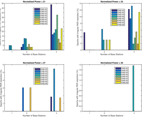
3.10 Relation between % of Irregular PER epochs and different power levels . . . 43
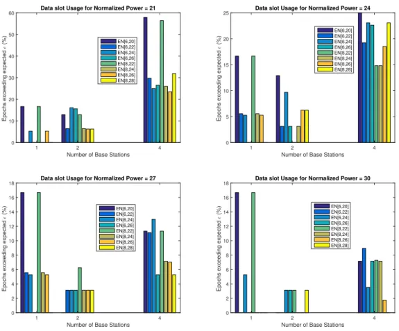
3.11 Relation between % of epochs exceedingǫand different power levels . . . . 44
L i s t o f F i g u r e s
3.13 effect ofΩon average throughput per number of base stations. . . 46
3.14 effect ofΩon average energy per useful packet. . . 47
3.15 effect ofΩon average service time. . . 47
3.16 effect ofJon average delay. . . 48
3.17 effect ofJon aggregated throughput with confidence intervals of 95%.. . . . 48
3.18 effect ofJon EPUP. . . 49
3.19 effect ofJon maximum service time. . . 50
3.20 effect ofJon reliability requirements.. . . 51
3.21 Queuing delay for varyingΩand 1BS . . . 52
3.22 Queuing delay for varyingΩand 2BS . . . 52
3.23 Queuing delay for varyingΩand 4BS . . . 52
3.24 Queuing delay for varyingJ and 1BS . . . 53
3.25 Queuing delay for varyingJ and 2BS . . . 53
3.26 Queuing delay for varyingJ and 4BS . . . 53
3.27 CDF of queueing delay for various MTs initial distributions . . . 54
3.28 Zoomed in section of figure 3.27 . . . 54
3.29 Variation of epochs imbalance. . . 55
3.30 Queuing delay CDF for initial distribution of 50/50 . . . 56
3.31 Queuing delay CDF for initial distribution of Low Power . . . 57
3.32 Queuing delay cdf for a random initial distribution . . . 57
3.33 Representation of the systemClass and all the methods (bottom rectangle). . 61
3.34 Simulator diagram. . . 62
3.35 Epoch power control algorithm . . . 63
3.36 Process before the simulator enters into the transmission loop. . . 64
3.37 Example of a generated scenario. . . 65
3.38 Example of a Stats Table with 20 MTs and 400% load . . . 66
3.39 Example of a Log Table with 20 MTs and 400% load. . . 66
L i s t o f Ta b l e s
3.1 Standard deviations and Variances of the disbalance metric . . . 56
3.2 Standard deviations and Variances of the disbalance metric discouting the first 20 epochs . . . 56
3.3 Standard deviations of the disbalance metric with varying load . . . 56
3.4 Variances of the disbalance metric with varying load . . . 57
3.5 Variances of the disbalance metric with varying load . . . 58
A c r o n y m s
5G The fifth generation of mobile networks.
AID Association identifier.
AP Access Point.
APC Active Power Control.
ATL-S-MACA Adaptive Traffic Load slotted MACA.
BER Bit Error Rate.
B-NDMA Blind Network Diversity Multiple Access.
BS Base Station.
CDF Cummulative Distribution Function.
CP Cyclic Prefix.
C-RAN Cloud Radio Network.
CDMA Code Division Multiple Access.
CERA Code Expanded Random Access.
CoMP Coordinated multipoint.
CSI Channel State Information.
CTS Clear-To-Send.
DAS Distributed Antenna System.
DC Diversity Combining.
E2E End-to-End.
ELL Extreme Low Latency.
eMBB enhanced Mobile Broadband.
EPUP Energy Per Useful Packet.
AC R O N Y M S
f-OFDM filtered OFDM.
FBMC Filter Bank Multicarrier.
GFDM Generalized Frequency Division Multiplexing.
H-ARQ Hybrid Automatic Repeat Request.
H2M Human to Machine.
H-NDMA Hybrid automatic repeat request Network Diversity Multiple Access.
IB-DFE Iterative Block Decision Feedback Equalization.
ICI Inter-Cell Interference.
IFFT Inverse Fast Fourier Transform.
IoT Internet of Things.
ISI Inter Symbol Interference.
ITU International Telecommunication Unit.
LDS Low Density Spreading.
LoRa Long range.
LPWA Low Power Wide Area.
LSAS Large Scale Antenna Systems.
LTE Long Term Evolution.
LTE-A LTE Advanced.
M2M Machine to Machine.
MAC Medium Access Control.
MACA Multiple Access with Collision Avoidance.
MBB Mobile Broadband.
MIMO Multiple-input-multiple-output.
MIMO-NOMA MIMO-NOMA transmission technique.
mMTC massive Machine-Type Communications.
MPA Message Passing Algorithm.
MPD Multi-Packet Detection.
MPR Multipacket reception.
MT Machine Terminal.
NDMA Network Diversity Multiple Access.
NGMN Next Generation of Mobile Networks.
AC R O N Y M S
NOMA Non-Orthogonal Multiple Access.
OFDM Orthogonal Frequency Division Multiplexing.
OFDMA Orthogonal Frequency Division Multiple Access.
OOB Out of Band.
PAPR Peak-to-Average Power Ratio.
PDMA Pattern Division Multiple Access.
PER Packet Error Rate.
PHY Physical.
QoE Quality of Experience.
QoS Quality of Service.
QPSK Quadrature Phase Shift Keying.
RACH Random Access Channel.
RAP Random Pilot Sequences.
RAW Restricted Access Window.
RFID Radio Frequency Identification.
RTS Request-To-Send.
S-MAC Sensor MAC.
SC-FDE Single Carrier with Frequency Domain Equalization.
SC-FDMA Single Carrier Frequency Division Multiple Access.
SC FDM Single Carrier Frequency Division Multiplexing.
SCMA Sparse Code Multiple Access.
SE Spectral Efficiency.
SIC Successive Interference Cancellation.
SISO Single-Input Single-Output.
SNR Signal to Noise Ratio.
SPR Single Packet Reception.
TDMA Time Division Multiple Access.
TTTL Time To Transmit Latency.
TUOS Terminal Unique Orthogonal spreading-Sequence.
AC R O N Y M S
UFMC Universal Filtered Multicarrier.
URLLC Ultra-Reliable and Low Latency Communication.
WSN Wireless Sensor Network.
WUR Wake-Up Radio.
WURx Wake-Up Receiver.
C
h
a
p
t
e
r
1
I n t r o d u c t i o n
In a largely connected world, the number of devices that access the Internet is increasing
year by year. During the last decade, the increase in mobile traffic has mainly been
caused by the global adoption of smartphones and the corresponding applications, which have caused the cellular networks to move from voice-centered to data-centered services. These applications require high data rate, global access to the Internet, and seamless
mobility, which have been the main driver of cellular standards in the past [1].
As technology evolves and new technologies appear, e.g. Internet of Things (IoT),
paving the way towards a paradigm of ubiquitous connectivity, the realization of smart cities in which homes, vehicles, and mundane objects are endowed with sensing and
communication capabilities will accelerate towards 2020 [2]. Thanks to the advances in
communications technology, machines can be connected and reached cost effectively and
will soon become an integral part of the global information network [3].
M2Mdeployments and services are expected to grow exponentially in diverse areas
such as transportation, utilities, health, and environment. M2Mdeployments will
gen-erate many new and diverse forms of data traffic with varying requirements in terms
of delay, reliability, energy consumption and security. This new scenario poses a new
set of requirements not currently supported or optimized byLong Term Evolution (LTE)
andLTE-Acellular systems, which have the primary focus ofMobile Broadband (MBB)
communications [1].
Therefore, a new generation of mobile networks is needed to attend these novel
re-quirements and services - the 5thgeneration5G.5Gis expected to enable a fully mobile
and connected society and to empower socio-economic transformations [4]. TheNext
Generation of Mobile Networks (NGMN)formulated the following vision of the fifth gen-eration [4]:"5G is an end-to-end ecosystemto enable afully mobile and connected society.
C H A P T E R 1 . I N T R O D U C T I O N
cases,delivered withconsistent experience,and enabled bysustainable business models."
Hence in5G, there is a need to push the envelope of performance to provide, where
needed, for example, much greater throughput, much lower latency, ultra-high reliability,
much higher connectivity density and higher mobility range. 5Gwill also operate in a
highly heterogeneous environment characterized by the existence of multiple types of access technologies, multi-layer networks, multiple types of devices and multiple types of
user interactions. In such an environment, there is a fundamental need for5Gto achieve
seamless and consistent user experience across time and space [4].
In addition of handling a heterogeneous environment and supporting a wide range
of devices,5Gmust support a high variety of use cases like broad-band access in dense
areas, massive IoT or massive M2M, extreme real-time communications, lifeline
com-munications and ultra-reliable comcom-munications [4]. The latter is drawing quite some
attention, as it is envisioned to be a use case not only with significant growth in areas as automotive, health and assisted living applications, but a new world in which industries
from manufacturing to agriculture rely on reliableM2M. Another interesting
applica-tion of ultra-reliable communicaapplica-tions involve remote operaapplica-tion and control, that require
extreme low latency as well [4]. This subsection is called theURLLC, a type of M2M
communication with low latency and high reliability strict requirements.
URLLCis targeted at emerging applications in which data messages are time-sensitive and must be securely delivered end-to-end. However, balancing out low latency and high
reliability presents itself as an immenseQuality of Service (QoS)challenge, introducing
several challenges in the wireless system design. Moreover, attaining the parameters
established for this type of communication1, and supporting these standards for an
over-whelming number of devices is hard to accomplish [5].
The work developed in this dissertation intends to address the unique environment
introduced in5G, with the goal of extending an existingM2M Hybrid automatic repeat
request Network Diversity Multiple Access (H-NDMA) MACprotocol to make it suitable for URLLC. The MAC protocol is adapted to work with multiple base stations and a power control algorithm is proposed.
1.1 Research goals and contributions
This dissertation explores the capacity enhancement through the spatial densification of the M2M H-NDMA protocol, aiming to provide ultra-reliable low latency communication services for M2M networks. A new version of the M2M H-NDMA protocol is proposed in this thesis, whose goals are:
• Make the M2M H-NDMA MAC protocol suitable for a multi base station scenario;
13GPP requirements forURLLCincludes the hard latency of 1ms over the air interface and the system reliability in terms of successful packet rate delivery of 1−10−5
1 . 2 . D I S S E R TAT I O N ’ S O U T L I N E
• Introduce power control schemes into the protocol and optimizing power configu-rations for the multi base station scenario.
Both of these goals were accomplished, contributing to:
• Analysis of the performance of the M2M H-NDMA protocol in a multi base station
scenario and the effect of power spreading in such environment regarding ultra
reliable low latency requirements.
• An evolved version of the M2M H-NDMA protocol was designed and a system level simulator was implemented using MATLAB.
1.2 Dissertation’s outline
The dissertation structure is as follows: Chapter 2 overviews an literature review, de-scribing the related work to the dissertation scope. It starts by dede-scribing existing access schemes that are already in use, and presents other access schemes and MPR techniques that are considered enablers for 5G URLLC. A small description of the state of the art on M2M MAC protocols is given, with a focus on mission critical M2M MAC protocols. Chapter 3 starts by describing the new scenario considered - a distributed antenna system. It then presents the previous M2M H-NDMA protocol and introduces the changes needed to be made for making the protocol suitable to work in the new environment. A detailed power study is conducted, to analyze the performance of various transmissions non or-thogonal multiple access (NOMA) power levels and evaluate the best power gap between them, in order to guarantee reliability and reduce delay. Ensuing, it is presented a power
control scheme, using different power levels distribution strategies, and an analysis is
C
h
a
p
t
e
r
2
R e l a t e d Wo r k
2.1 Introduction
Until now, from the previous mobile generations up to the current 4G, or as it is called
LTE-A, all had an application that propelled the mobile communication market growth, always searching for improvement of the previous generation to keep up with these new apps.
As stated in [6], in the past few years the development of a5Gvision led to the
consen-sus that the latest generation of cellular systems will be driven by various recently rising
use cases, related to major drivers such asIoT, Gigabit wireless connectivity, tactile
inter-net and ultra-reliable communications [7], whereas the previous generations of cellular
systems design mainly focused the increase of spectral efficiency to indulge
bandwidth-hungry applications for human users. As we can tell from these drivers, there will be
a new paradigm shift on communication types that5Gwill need to address, associated
with the encompassing ofHuman to Machine (H2M)as well asM2Mcommunications.
With the upcoming of new use cases come new requirements. Based on the current
trends, 5Gmobile networks will have to address defying challenges that are not
ade-quately addressed by state-of-the-art deployed networks [8]: higher capacity, higher data
rate, lowerEnd-to-End (E2E) latency, massive device connectivity, reduced capital and
operations cost and consistentQuality of Experience (QoE)provisioning.
Specifically, forM2Mcommunications, energy efficiency is a mandatory requirement,
since a significant fraction of the devices involved in this type of communication is
ex-pected to be battery operated [9], and some of these devices will be deployed in remote
locations, so having a long battery life is especially important. Most of the current solu-tions for low power are designed for short range connectivity, that sometimes might not
C H A P T E R 2 . R E L AT E D WO R K
technology has been specifically designed with the objectives of low energy consumption
and wide coverage [10]. Currently, theLong range (LoRa)is one of the prevailingLPWA
technology for buildingIoTnetworks, but all fail to provide theURLLCservice level.
A novel approach toPHYlayer design, with groundbreaking changes is required to
provide the services portrayed above. With the ever-increasing growth ofM2M
communi-cations, the new generation of mobile communications must be able to deal with different
types of services with different types of requirements, i.e. providing connection to a
user for downloading a video and at the same time allowingM2Mthat has completely
different requirements, and handle this without compromising any of the services. 5G
will need to support the diversity of devices and service requirements in a scalable and efficient manner [8].
It is pointed out in [11] that since there will be a need of co-existence of human
cen-tric and machine-type services, or perhaps even hybrid of these two, the International
Telecommunication Unit (ITU)has established three representative service classes: en-hanced Mobile Broadband (eMBB), massive Machine-Type Communications (mMTC), and URLLC. The latter attracted a lot of attention recently because it can provide a real-time interaction among machines and humans, so that services like tactile internet,
automated driving and augmented reality can be realized in a near future [12].
Of these three services, thePHYlayer design of theURLLCservice is by far the most
defying and problematic, mainly because it must fulfill two clashing requirements: low latency and ultra-high reliability. If we try to minimize latency, it will imply the use of a short packet, resulting in a serious degradation of the channel coding gain. Nonetheless, if we try to enhance reliability, more resources will be needed, resulting ultimately in latency increase [11].
One can conclude from what is depicted above, that the current mobile generation
deployed will not suffice to the arise of these new challenges and requirements. For
instance, although various efforts have been made to have the current deployed networks
support theIoTneeds, many of the envisaged new applications impose requirements of
ultra-low latency and ultra-high reliability, which are not easily supported by current
networks [8]. Also, mentioned in [11], 3GPP has decided that the physical layer latency
ofURLLCshould not surpass 0.5 ms, and in order to ensure this, theTime To Transmit Latency (TTTL)should be in the order of hundreds of microsecond. Since theTTTLof theLTE-Anetworks is fixed to 1 msec, it simply cannot satisfy thePHYlayer constraint imposed.
The Orthogonality and synchronization requirements ofLTE-A PHYlayer, based on
Orthogonal Frequency Division Multiplexing (OFDM)andSingle Carrier Frequency Di-vision Multiplexing (SC FDM)are also obstacles for its use in the new 5G architecture [7]. Synchronism means that the senders operate with a common clock for their processing. Orthogonality means that no crosstalk occurs in the receiver’s signal detection process.
However, for cases like themMTCscenario, sensor nodes usually transmit different types
2 . 2 . O R T H O G O N A L M U LT I P L E AC C E S S S C H E M E S
of data asynchronously and traditionalOFDMcalls for different users to be highly
syn-chronized. Otherwise it leads to substantial interference among neighboring bands [11].
This scenario is an example of a case where orthogonality is destroyed, and as it is referred
in [7], this makes the noise pile up without bounds in theOFDM.
Devices and machines involved inM2Mgenerate bursty and sporadic traffic, meaning
that they are not always transmitting, and therefore should not be complied to follow the
synchronization of theLTE-A PHYlayer. Instead, they should only access the network
when they have information to transmit [7]. An effective way to do this would be to have
the sporadic traffic carried by non-orthogonal waveforms for asynchronous signaling in
the uplink.
TheLTE-Awaveform, with the plenteous guard band to other legacy networks, severely
deteriorates spectral efficiency and can prevent band usage [7], resulting from the strict
synchronism and orthogonality constraints within thePHYlayer. In this new paradigm
of uncoordinated interference, new waveforms and access and reception schemes are required, that implement sharp frequency notches, tight spectral masks to not hinder with legacy systems and to deal with uncoordinated interference as well as asynchronous signaling.
This chapter describes the related work on this area. It starts by describing some
current multiple access schemes, following by the introduction ofMultipacket reception
(MPR)and some techniques and concepts related to it, and finally giving a brief overview
of theM2Mcommunication requirements, with emphasis onURLLC.
2.2 Orthogonal multiple access schemes
2.2.1 Orthogonal Frequency Division Multiple Access
The expanding of wireless digital communication resulted in a demand for wireless
sys-tems that are reliable and have a high spectral efficiency. This demand for higher data
rates led to a wider use of the bandwidth, resulting in severe frequency selectivity of the
channel, consequently making theInter Symbol Interference (ISI)more serious [13].
In a single carrier communication system, time equalization is done to get rid of
ISI. However, in the wide band channel scenario, the length of the time domain filter
to achieve equalization is prohibitively large since it linearly increases with the channel response length [13].
A way to lessen the frequency selective fading in a wide band channel is to use
multi-carrier techniques. A multimulti-carrier technique [13] subdivides the whole bandwidth of the
channel into smaller sub bands, around each subcarrier. With such techniques come many advantages that involve their robust communication and stable interference management, as well as facilitating dynamic frequency reuse techniques and exploring multiuser
C H A P T E R 2 . R E L AT E D WO R K
TheOFDMis a multicarrier modulation technique which uses orthogonal subcarriers
to transmit information. As explained in [13], in the frequency domain the bandwidth
of a subcarrier is intended to be smaller than the coherence bandwidth of the channel, so each sub-channel is seen as flat fading channel, simplifying the equalization process. In the time domain, by splitting a high rate data stream into multiple lower rate data
streams that are parallelly transmitted,OFDMeffectively solves theISIproblem in wide
band communications.
TheLTEandLTE-AemployOrthogonal Frequency Division Multiple Access (OFDMA)
as the multiple access scheme for the downlink [14]. Multiple Access is done by allocating
different groups of subcarriers simultaneously to different users [13], allowing
simulta-neous low data rate transmission from numerous users. This technique improvesOFDM
sturdiness to fading and interference.
2.2.2 Single Carrier Frequency Division Multiple Access
InLTEandLTE-A OFDMAis used for the downlink, as mentioned above. For the uplink,
Single Carrier Frequency Division Multiple Access (SC-FDMA)is also used and it is based on Single Carrier with Frequency Domain Equalization (SC-FDE)[13]. The SC-FDEis a single carrier modulation combined with frequency domain equalization, and it is a
different solution to theISIproblem.
The main advantage ofSC-FDMA versus OFDMAis this type of transmission has
lowerPeak-to-Average Power Ratio (PAPR), sinceSC-FDMAspreads the energy of one
subcarrier over the range of all subcarriers, prior to the computing of the Inverse Fast
Fourier Transform (IFFT). Consequently, the spectral nulls in the channel are reduced
with averaging, andPAPRis reduced [13]. Having lowPAPRin the transmit waveform
results in less power consumption in the mobile station comparing to anOFDMA
trans-mission, thus enhancing the system uplink throughput.
Another reason for using SC-FDMA is also given in [13]: The architecture of the
receiver in the case ofSC-FDMAis more complex than the architecture of theOFDMA
receiver. However, the design of the power amplifier used in the transmitter is simpler
in the case ofSC-FDMA due to the lower value ofPAPRin this case. This observation
reinforces the use of SC-FDMA as an uplink scheme, since the power efficiency and
complexity are more important for mobile stations than for the base station.
2.2.3 Code Division Multiple Access
Code Division Multiple Access (CDMA) is a technique that has been widely used in
wireless communication since it has great bandwidth efficiency.
CDMAis a spread spectrum technique that assigns each node with a unique code to
spread each bit of the data sequence. InCDMAnetworks, the channel can be partitioned
2 . 3 . M U LT I PAC K E T R E C E P T I O N
by different codes. A sub-channel can be represented by a spreading code to allow
simul-taneous transmissions to occur on the same frequency bandwidth without interference [15].
Another way to explain it is given in [16]: CDMAapplies a set of orthogonal codes
to encode the data from different users before transmitting in a shared communication
media. Hence, it allows multiple users to access the communication media at the same
time by separating data from different users in the code domain.
2.2.4 Other Modulations for OMA
In this section, we will briefly give an overview of some new types of modulation
tech-niques envisioned for5Gnetworks. The modulations mentioned below will fall into two
categories: Modulations based on pulse shaping and based on sub-band filtering.
Pulse shaping, which is also considered as a subcarrier-based filtering, can
success-fully reduce Out of Band (OOB)leakage [17]. According to the Heisenberg-Gabor
un-certainty principle, the time and frequency widths of the pulses cannot be decreased at the same time. Hence, waveforms based on pulse shaping are typically non-orthogonal
in both time and frequency domains to uphold high spectral efficiency [17].
Fundamen-tally, modulations based on pulse shaping try to confine transmit signals within a narrow
bandwidth and in this manner alleviate theOOBleakage so that they can work in an
asyn-chronous scenario with a narrow guard band [17]. Two types of pulse shaping modulation
areFilter Bank Multicarrier (FBMC)andGeneralized Frequency Division Multiplexing (GFDM).
Sub-band filtering is another technique to reduceOOBleakage. In general,
modula-tions based on sub-band filtering achieve better performance in comparison to traditional
OFDM[17]. Two types of sub-band filtering areUniversal Filtered Multicarrier (UFMC)
andfiltered OFDM (f-OFDM).
All these access schemes are different and have their strengths and weaknesses, but
they have one thing in common: none of them considers collisions or if collision happens, they simply discard the packets. In the following section, the collision problem will be tackled and shown how to make use of it.
2.3 Multipacket Reception
In traditional communication systems, receivers can only receive a packet from each
source at a time. These types of systems are classified asSingle Packet Reception (SPR).
C H A P T E R 2 . R E L AT E D WO R K
worsen the situation, as the number of packets that collide escalate, so does the number
of retransmissions, contributing to further degradation of the throughput [18].
However as stated in [19], there is no fundamental reason that collided transmissions
cannot be recouped by other means, for example, coding and signal processing. The
advent of multiaccess techniques such as CDMAand multiuser detection led to a new
examination of random access under a multiuserPHYlayer [19].
In the 90’s, a newMPRmodel was proposed, where the main premise that diff
erenti-ates from the collision model, is given simultaneous transmissions, the reception can be
described by conditional probabilities instead of deterministic failure [19].MPRsystems
are capable of simultaneous decoding of multiple packets from more than one source concurrently, even if a collision arises, it is still possible to decode the packets that were
transmitted [18]. Figure2.1represents the classification of MPRtechniques suggested
in [18]. These techniques are divided in three main classes, corresponding to where the
MPRshould be enabled. This classification is given based on three perspectives:
Figure 2.1: Categorization of techniques applied for MPR (adapted from [18])
• Transmitter perspective: this type of techniques demands a significant effort by
the transmitter. The idea behind this technique is to separate different signals into
orthogonal signaling dimensions, allowing multiple users to share the same channel.
CDMAandOFDMAare examples of this class [18].
• Transceiver perspective: In this type of techniques, transmitters and receivers
ought to collaborate on some operations to enableMPR. An example of this class is
multi antenna MIMO.
• Receiver perspective: This type of techniques involves solely the receiver for de-coding several packets simultaneously. Comparing to the previous classes, this one
comes closer to the ideal ofMPR, which is to shift the responsibility from
transmit-ters to receivers [18].
2 . 3 . M U LT I PAC K E T R E C E P T I O N
A fleeting description of some the techniques that fall on the classes presented above is given in the following subsections. It will describe some techniques such as MIMO,
Network Diversity Multiple Access (NDMA) andH-NDMA, that is a hybrid solution, which means that uses more than one of the techniques mentioned above. It will also be
presented a brief description onNon-Orthogonal Multiple Access (NOMA)and some use
cases.
2.3.1 MIMO
Multiple-input-multiple-output (MIMO)is a technique for sending and receiving various data signals simultaneously over the same radio channel, exploiting multipath
propaga-tion. A multi-antennaMIMO system can accomplishMPRby taking advantage of the
spatial diversity of the transmissions. In such a system each antenna corresponds to a
different channel characteristich(t), implying that a packet sent from one antenna can be
distinguished from the one sent with another antenna [18].
MIMO has been an essential element for current mobile generations and wireless
standards, and recently it has been considered a key enabler for5G, but the concept is
taken to a different level – massiveMIMO. In [20], it is defended that massiveMIMO
or also known as Large Scale Antenna Systems (LSAS)along with the implementation
ofRandom Pilot Sequences (RAP), will be an important enabler for5G: By using many
antennas at theBase Station (BS)s that concurrently serve many devices through spatial
multiplexing, channel hardening can be achieved, eliminating small-scale fading as well
as facilitating spatial multiplexing to many devices simultaneously. Each device eff
ec-tively has an exclusive focused data beam, that does not suffer from small-scale fading
and interference.
This is great for amMTCscenario, but for theURLLCcase, the authors in [20] suggest
assigning specific pilot sequences toURLLC, since the number ofURLLCdevices would
be smaller than the number of pilot sequences available. When critical low-latency data arrives, it can be sent with very high reliability, in a grant free kind of scheme. This
means thatLSAScan be an enabler forURLLC, due to the fact that it can provide a large
diversity order as well as large spectral efficiency simultaneously [12], while meeting the
latency and reliability requirements. In conclusion,LSAScan be an important enabler
forURLLCin the 5th generation mobile networks.
2.3.2 NOMA
In the sections above, some OMA schemes were presented that are in use in today’s current mobile generations. However, when we talk about massive simultaneous random
access and low latency, two very important requirements for the5Gmobile generation, it
is clear that current OMA schemes will not suffice.
The main reason for this is that in OMA techniques, users in each cell are allocated
C H A P T E R 2 . R E L AT E D WO R K
means that resources are not shared, meaning a user with poor channel conditions has a resource block for its exclusive use, and does not take advantage at its fullest, leading to poorSpectral Efficiency (SE). This combined with the scenario of having tens of thousands
User Equipments (UEs), all trying to perform random access procedure for uplink access,
leads to network congestion, unforeseen delay and high power consumption [22].
NOMAhas been recently recognized as a promising technique for improving spectral
efficiency. The main premise of this technique is the fact that it uses the power domain for
multiple access, thus allowing users to use resources simultaneously. Taking the example ofOFDMA, where subcarriers are allocated to specific users, if those have poor channel
conditions it will affect theSEnegatively. WithNOMA, each user can access all subcarrier
channels, therefore bandwidth resources assigned to users with poor channel conditions can still be accessed by the ones with stronger channel conditions, significantly improving theSE[23].
Figure 2.2: frequency/power domain user multiplexing using NOMA (adapted from [24])
This means NOMAcan potentially provide the chance to meet the demanding 5G
requirements, as we can tell by some of its key features [17]:
1. Improved SE: NOMAexhibits highSE, since each resource block can be exploited by multiple users.
2. Ultra-high connectivity: supporting multiple users within one resource block
meansNOMAcan conceivably bolster massive connectivity for an immense number
of smart devices, especially forIoTscenarios andM2M.
3. Relaxed channel feedback: InNOMA, perfectChannel State Information (CSI)is not required at the BS, needing only the received signal strength in the channel feedback.
4. Low transmission latency: for uplinkNOMA, there is no need to schedule requests
from users to the BS (in the time domain), like in OMA schemes. Therefore, a
grant-free uplink transmission can be done in NOMA, lowering drastically the
transmission latency.
Most of current NOMA schemes can be put into three categories: Power domain
NOMA, code domainNOMAand multiplexing in multiples domains, meaning it uses
2 or more domains to multiplex users (i.e. power, code, spatial). Brief introductions to some use cases within these categories are given below.
2 . 3 . M U LT I PAC K E T R E C E P T I O N
2.3.3 Basic power domain NOMA
Power domainNOMAis about supporting multiple users within the same resource block,
and distinguishing them with different power levels, resulting in more connectivity and
higher throughput given limited resources [17].
Let us take figure 2.3 as an example. The BS will send a superimposed mixture
containing two messages for two users. Unlike conventional schemes,NOMAusers with
poor channel conditions get more transmission power.
The message to the user with the weaker channel condition is allocated more trans-mission power, which guarantees that this user can distinguish its message directly by considering other user’s information as noise. Still, the user with stronger channel condi-tion needs to first detect the message for its partner, then subtract this message from its
observation and finally decode its own information. This procedure is calledSuccessive
Interference Cancellation (SIC)[23].
Figure 2.3: Illustration of downlink NOMA with SIC (adapted from [24])
UsingNOMAwith SIC has been proven to be beneficial. The results in [22] show
that applying a protocol based on these two techniques to deal with random access, they achieved 30% more throughput compared with an orthogonal random access scheme, for a large number of user equipments.
Another use case of these two techniques is cooperativeNOMA, where the users with
stronger channel conditions act as relay to aid users with frailer channel conditions [17],
[23]. After the stronger user carries outSICfor the weaker user, the stronger user acts as
a relay to forward decoded information to this weaker user. So, it receives two copies of
the message from different channels, thus improving the reliability of this user with the
C H A P T E R 2 . R E L AT E D WO R K
Figure 2.4: Illustration of cooperative NOMA (adapted from [23])
2.3.4 Code domain NOMA
Code domain NOMAis about supporting various transmissions within the same
time-frequency resource block by doling out different codes to different users. This kind of
NOMAtechnique has a certain spreading and shaping gain, at the expense of additional
signal bandwidth as compared to power domainNOMA[17].
Some use cases of this type of technique areLow Density Spreading (LDS)andSparse
Code Multiple Access (SCMA). The basis of these techniques are essentially the same idea that one user’s information is spread over numerous sub-carriers, but the number of subcarriers doled out to each user is lower than the aggregate number of subcarriers, and this low spreading (sparse) guarantees the number of users using the same subcarrier is
not too big, so that the system complexity remains manageable [25].
Figure 2.5: An example of an SCMA system with six users and four subcarriers (adapted from [25])
In figure 2.5, we can see an example of anSCMA system with six-users and four
2 . 3 . M U LT I PAC K E T R E C E P T I O N
subcarriers. The sparse feature is visible due to the fact each user only employs two subcarriers (the ones in each column of the matrix). It is important to note that since
each user’s message at different subcarriers are encoded together,SCMArequires joint
decoding at the receiver, where aMessage Passing Algorithm (MPA)is used to guarantee
low complexity. This is an important feature ofSCMA, setting it apart from power domain
NOMA, as joint decoding rather thanSICis employed [25]. However, even withMPA, the
complexity might still be high for user devices. In this caseSCMAconsiders clustering
based on theCSIand allocating different powers to different clusters. Thus when transmit
powers vary among different clusters,SICcan be applied, which resembles power-domain
NOMA, and within each cluster,MPAcan be applied to distinguish users. Combining
these two techniques can diminish the complexity of the receiver greatly [17].
Code domainNOMAtechniques are able to support large levels of connectivity, but
they also introduce redundancy, and for a massive device scenario with low latency
re-quirements, it might inevitably degrade the SE at a certain point [21].
2.3.5 Multiplexing in multiple domains
NOMAtechniques are not limited to use only one domain to multiplex users. Some
solu-tions forNOMAhave been proposed to multiplex in multiple domains, like power, code
and spatial with the end goal to provide massive connectivity for5Gnetworks [17]. In
this section, we will briefly introduce schemes that utilize more than one domain to
mul-tiplex users: Pattern Division Multiple Access (PDMA)andMIMO-NOMA transmission
technique (MIMO-NOMA)transmission.
InPDMA, non-orthogonal patterns are allocated to different users to carry out
multi-plexing, which are designed in the multiple domains of power, code and space. PDMA
resemblesSCMA, being the main difference the fact that the amount of resource blocks
used by each user can differ, i.e. the number of subcarriers occupied by one user is not
necessarily much smaller than the total number of subcarriers [25]. This means one user
could be able to transmit and receive on all subcarriers, unlikeSCMAthat strictly imposes
the sparse feature.
MIMO-NOMAtransmission basic idea is to extend the use ofNOMAto the case in
which both BS and users are equipped with multiple antennas, which results in this
MIMO-NOMAcombination [23]. The application ofMIMOtoNOMAis essential, since
the spatial degrees of freedom empowered byMIMOare pivotal for meeting the
perfor-mances requirements of5Gnetworks [25].
However, there some issues with this type of multiplexing. The main difficulty is the
complexity of the receivers. The extension ofNOMAwith spatial multiplexing to more
than two users with multiple carriers requires user clustering and resource allocation in
multi-dimensional space, making that an analytical and computational challenge [23].
User ordering inMIMO-NOMAscenarios is also a challenging task, since inSingle-Input
C H A P T E R 2 . R E L AT E D WO R K
with multiple antennas, the user’s channel are vectors or matrices, making user ordering
in consonance with their channel conditions in aSISOfashion hard [25].
In conclusion, MIMO-NOMA techniques are great for providing more degrees of
freedom and improving system throughput, but at the cost of more complexity at the user side, that in some scenarios might not be feasible (i.e. having multiple antennas in a small sensor making the receiver very complex).
2.3.6 Network Diversity Multiple Access
NDMAis a protocol that handles collisions by using time diversity multipacket reception.
NDMAobliges all terminals engaged in a collision of P packets to retransmit their
packets P – 1 times. The P transmissions are required to adequately separate P colliding
packets [26]. Therefore inNDMA, packets with collision are not discarded as in the
con-ventional protocols, being instead stored in memory for further processing [27]. There are
two classes ofNDMAprotocols, regarding the way they identify the number of terminals
engaged in a collision: ClassicNDMAapplies terminal-specific orthogonal ID sequences
in the packet headers. Blind Network Diversity Multiple Access (B-NDMA) protocols
apply a collision multiplicity rank detection algorithm [26].
However, the use of these orthogonal IDs in classicNDMAmay lead to bandwidth
inefficiency as the user population increases, like in amMTCscenario. Also, theNDMA
MACprotocol is not able to deal with lowSignal to Noise Ratio (SNR)scenarios. For these
reasons, a H-NDMA(orHybrid Automatic Repeat Request (H-ARQ)NDMA) protocol
is proposed in [26] where terminals are presumed to be low resource battery operated
devices and theBSis a high resource device that runsMPRalgorithm with H-ARQ error
control in real time. TheH-NDMAtechniques reuse packets with errors from past
trans-missions to improve packet reception on following transtrans-missions. Figure2.6depicts the
H-NDMAproposed scheme.
Results from simulations made in [26] show the proposed H-NDMA protocol
im-proves the network capacity and also decreases packet delay and energy expenditure,
compared to basicNDMAprotocol, despite some performance degradation due to
mis-detections and false alarm errors. H-NDMApresents itself as a viable option for the5G
mobile networks. Still, since H-NDMArequires a somewhat strict synchronization in
time for terminals to identify the epoch beginning, in theURLLCcase this characteristic
might be a disadvantage, causing some delay that might not be tolerable for mission
criti-calM2Mcommunications (i.e. remote surgery). However, some breakthrough was made
in [28] where the authors adapted theH-NDMAprotocol to provideExtreme Low Latency
(ELL)forM2Mservices and advanced power saving mechanism with good results as long as the total load is controlled.
2 . 4 . M AC P R O T O C O L S F O R M 2 M C O M M U N I CAT I O N S
Figure 2.6: H-NDMA MPR scheme (adapted from [26])
2.4 MAC protocols for M2M communications
In the sections above, we have discussed some PHYlayer-based techniques that could
fulfill the requirements ofM2Min5G. However, to fully take advantage of the
applica-tions given byM2Mcommunications, all layers must provide a certain level of support
to attain the service requirements.
In this section, MAC layer requisites regarding M2M communications will be
de-scribed, and classification ofMACprotocols will be given, providing some examples for
each class. We will address with some depth the mission critical MACs, forWireless
Sensor Network (WSN)s scenario.WSNs comprise of small self-sufficient devices called
nodes or motes that gather information such as pressure, temperature or vibration from
their physical surroundings [29]. Finally, an introduction to an energy saving concept –
theWake-Up Radio (WUR), will be given.
2.4.1 The M2M MAC requirements
TheMAClayer is primarily in charge of channel access for nodes within a network that
use a shared medium. The criticalMAClayer challenge forM2Mcommunications lies in
facilitating channel access to an enormous amount of devices while supporting the diverse
service requirements and unique traffic characteristics of devices inM2Mnetworks [9].
Therefore, for supportingM2MtheMACprotocols must be designed with a rich set
of requirements to address the needs of the overlaying applications and scenarios. Those
requirements are the ensuing [9]:
• Data throughput - MAC protocols for M2M communications must be highly effi
C H A P T E R 2 . R E L AT E D WO R K
channel,MACprotocols should attempt to minimize the time wasted due to
colli-sions and control messages exchange. Equivalently, the throughput must be high to accommodate the very large number of devices.
• Scalability– Scenarios withM2Mcommunications are anticipated to have several
nodes. The node density is foreseen to increase as the deployment of application
scenarios with M2Mcommunications becomes more prevalent. Besides, the
net-work conditions might always be in constant changing, having nodes leaving and
entering. It is then critical that the MAC protocol be effortlessly adaptable and
balanced smoothly to changing node densities with slight or no control information exchange and maintained fairness even after addition of new devices.
• Energy efficiency– This is one of the most important design thoughts for three
rea-sons, which are: 1) the reality that many of the devices inM2Mnetworks are
pre-dicted to be battery operated; 2) the economic impact of the power usage by the communication infrastructure; and 3) the environmental impact of the power ex-pended. Collisions during channel access are a major cause of power consumption that ought to be lessened to the best degree conceivable. Conventional methods to
reduceMACenergy consumption comprise of lessening collisions, sleep scheduling,
power control and reducing idle listening.
• Latency- For many of the applications that depend onM2Mcommunications,
net-work latency is a crucial factor that rules the effectiveness and utility of the services,
especially when we talk about applications or scenarios that rely on tight latency and reliability requirements to be successful, like intelligent transportation systems
or e-health applications. In addition, the MAC protocol should guarantee
long-term as well as short-long-term fairness, so that all devices can have an equal chance (or proportional to their priority) to send their message.
• Cost effectiveness– To makeM2Mcommunications-based systems a reality, the
de-vices must be cost effective so that it is affordable to deploy them. AMACprotocol
that has many desired properties but that relies on complex and pricey hardware is
not convenient. Hence theMACprotocol should be designed to function effectively
on simple hardware, especially considering the budget saving potential it can have when it comes to large scale deployments.
• Coexistence- A significant fraction of the access networks forM2Mcommunications
are expected to operate in the unlicensed bands. This means it is expected for
manyM2M access networks to be deployed near and independently in the same
unlicensed band. Besides they also will have to coexist with other networks that traditionally operate in the unlicensed band (e.g. Wi-Fi and Bluetooth). Therefore, issues such as collisions due to the hidden terminals from neighboring networks
must be addressed at theMAClayer.
2 . 4 . M AC P R O T O C O L S F O R M 2 M C O M M U N I CAT I O N S
Some of these requirements and issues that come with them, can already be seen in
Radio Frequency Identification (RFID)technologies, where it is critical that the tags must
be energy efficient, and the tags can be correctly identified without missing a single one
[30], which is important to maintain the network scalability and stability. Also, in
pres-ence of unreliable channel conditions they still must guarantee throughput and latency thresholds, since the tags (if they are passive, being the case considered for comparisons) are powered for brief moments to exchange information and must do it with a high degree of success in that time. These issues, most commonly known as counting problems or
missing-tag detection as well as energy-time tradeoffs are explained and contributions to
them are made in [30], [31].
2.4.2 Classification of M2M MAC protocols
TheMACprotocols can be classified on the basis of the underlying mechanism of collision
avoidance and the organizational approach to sensor nodes [32]. One can classifyMAC
protocols based on architecture (distributed or centralized), based on the mode of opera-tion (random access, slotted access, frame slotted), and many other types of classificaopera-tions can be made [32].
For the sake of simplicity, most of the literature settles that currentMACprotocols
can be generally classified as contention-free, contention-based, and hybrid protocols that combine aspects of contention-based and contention-free, trying to leverage their
strengths and mitigate their weaknesses [9].
2.4.2.1 Contention-based MAC protocols
Contention-based MAC protocols are among the simplest protocols in terms of
imple-mentation and setup [9]. In these protocols, the nodes compete for the channel in several
ways to acquire the channel and transmit data. However, the biggest downside of this
approach is its severe energy inefficiency due to collisions, idle listening, control packet
overhead and overhearing[32].
This is especially perceived when the number of devices contending is very high, i.e. tens of thousands, causing serious latency due the increasing number of packets collisions,
consequently snowballing energy consumption and affecting the scalability. Nevertheless,
in [32] it is pointed out that being adaptive is the key to efficient energy usage, whether
these adaptations are made at traffic management or topology level.
An example of a contention-based protocol is the Fast-Adaptive Slotted ALOHA
(FASA). Originally proposed in [33], in this protocol, the network condition regarding the
number of backlogged devicesNt is estimated by using drift analysis on the access results
of the past slots [9]. Using this information, each node in the network is then given 1/Nt
as its transmission probability in each slot. TheBSis in charge of estimating the number
C H A P T E R 2 . R E L AT E D WO R K
2.4.2.2 Contention-free MAC protocols
Contention-free or scheduled-basedMAC protocols, erase the collision problem by
al-locating in advance transmission resources to the nodes in the network [9]. Some of
the known contention-free protocols includeCDMAandTime Division Multiple Access
(TDMA).
The main advantage of contention-freeMACscheme is energy efficiency due its
fea-tures such as the built-in duty cycle, being collision-free and the absence of control-packet
overhead [32]. However, in the context ofM2M communications, these protocols lack
flexibility and scalability, having a hard time adapting when the number of nodes in a
net-work varies or the load is bursty [9], [32]. Since a contention-freeMACscheme needs to
rigidly follow the assigned communication time slots, it requires frame synchronization which involves the complicated tasks of slot allocation and schedule maintenance, lead-ing to additional latency that decreases the throughput, and increases the nonproductive
consumption of energy [32].
An example of a contention-freeMACprotocol is cognitive polling, proposed in [34],
a protocol that uses cognitive radio techniques and considers M2Mdevices secondary
users [9]. The protocol is assumed to function in a scenario where network access is
frame-based and the BS broadcasts the information regarding the resource allocation
to the primary users in each frame [9]. In this protocol, M2M devices listen to these
broadcasts and use the vacant resources for communicating among themselves. Still, the
protocol does not grant any assurances on the throughput and delays theM2Mdevices
undergo, and is inefficient forM2Mdevices with bursty traffic [9].
2.4.2.3 Hybrid MAC protocols
As it was discussed above, contention-based protocols adapt with ease to changing net-work scenarios and are more appropriate for netnet-works with low loads. On the other hand, contention-free protocols get rid of collisions and can achieve a greater channel utilization
at higher loads [9]. To capitalize on the advantages of both categories, hybrid protocols
have been proposed that incorporate aspects of the contention-free and contention-based protocols.
These protocols work by switching between scheduled access at high loads and ran-dom access-based operation at low loads to avoid the degraded throughput and collisions of random access protocols at high loads and low channel utilization of schedule access
at low loads [9]. Hybrid protocols seem a promising approach for designingMAC
pro-tocols forM2Mcommunications. The main drawbacks of this type of protocols is their
scalability, since manyM2Mscenarios are envisioned to have node densities that might
be several orders of magnitude higher than the currently deployed ones. At such high densities, the frequency of collisions during the random access-based reservation phase of hybrid protocols turn into the bottleneck that keeps the network from accomplishing
2 . 4 . M AC P R O T O C O L S F O R M 2 M C O M M U N I CAT I O N S
a high utilization [9]. In addition, the advantages hybrid protocols provide come at the
cost of protocol complexity, and such complexity might not be feasible [32].
An example of a hybridMACprotocol is the IEEE 802.11ah. Its access mechanism
operates as follows [35]: every station connected to the Access Point (AP), receives a
unique identifier –Association identifier (AID). TheAIDcan be used to determine which
stations can access the medium. In particular, IEEE 802.11ah presents the concept of
Restricted Access Window (RAW)[35], during which just certain stations are permitted to
contend based on theirAIDs. This restriction improves the access efficiency, corroborated
by the number of stations whose transmissions do not experience collisions. RAWis split
into slots, and the number of them as well as their duration and assignment are indicated
in the beacon frame that is periodically sent by theAPto the stations. Every slot can be
assigned to a single or multiple stations, and only active stations contend in the assigned
slots [35]. An example of aRAWslot is presented in figure2.7.
Figure 2.7: Beacon frame announcing a RAW with six slots followed by a RA frame that
allocates slots for stations 1,3 and 5 (adapted from[35])
After viewing the three types ofMACprotocols, one can conclude that all of them
have their strengths and weaknesses, but when it comes to fulfillingM2Mcommunication
requirements, hybrid protocols clearly have an edge over the other types, although they
still need to be refined and enhanced. A taxonomy of moreM2Mspecific protocols and
a table comparing some of them according to various parameters are presented below
respectively in figures2.8and2.9.
One can conclude from figure2.9, that theM2Mprotocols presented meet and miss
some of the parameters. TheCode Expanded Random Access (CERA)protocol proposed
in [36], is based on an alteration of theLTEdynamicRandom Access Channel (RACH),
and intends to provide support for a greater number of devices as compared toLTE,
with-out increasing the resource requirements [9]. Although it achieves high throughput and
low latency, and can handle bursts, it is somewhat hard to scale, and it is not very energy
efficient. The IEEE 802.11ah, already presented above, does have a better scalability but
has a higher latency thanCERA. FASAis very simple to implement and has a low cost,
but it performs worse in the rest of the parameters compared to other protocols in the table.
Cognitive polling is able to achieve high energy efficiency due toM2Mdevices
C H A P T E R 2 . R E L AT E D WO R K
Figure 2.8: Taxonomy of M2M MAC protocols (adapted from [9])
Figure 2.9: Comparison table of M2M MAC protocols (adapted from [9])
among themselves, having no need to do spectrum scanning to find unused resources
[9]. However, this protocol has a very high latency.M2M LTEprotocol proposed in [37],
suggests simplifications that improve theMAClayer inLTE-Aefficiency and avoids
un-necessary control overhead. However, contention resolution and collision possibility are
not discussed, thus having low scalability. Adaptive Traffic Load slotted MACA
(ATL-S-MACA)protocol proposed in [38], is a modification of theMultiple Access with Collision Avoidance (MACA). Nonetheless, when comparing to the rest of the protocols, one can
see it performs just as worse as theFASAprotocol.
One interesting observation is that if it is desired a high throughput, low latency can
be provided but it is impossible to have high energy efficiency. If it is desired high energy
efficiency, throughput will go down and latency will go up, as it is shown in figure2.9
by the red markings. This means, that if it is desired high throughput, low latency and
on top of that high energy efficiency, the three big requirements forURLLC, theM2M
protocols shown cannot provide that. In the following section, the mission critical case
2 . 4 . M AC P R O T O C O L S F O R M 2 M C O M M U N I CAT I O N S
will be described, andMACprotocols designed forWSNs that fulfill the requirements
will be presented.
2.4.3 URLLC: Mission critical MAC for WSNs
As sensors have limited energy resources andWSNs are deployed in places where it is not
expected any human intervention to happen for a long time, for this application domain
(e.g. environmental monitoring), the main design goal is to have energy efficiency [29].
Therefore, current network protocols excel in the energy efficiency but only providing
simple best-effort data delivery.
WithWSNs extending their support to a number of other application domains like
patient monitoring, industrial process monitoring or military target tracking, the
afore-mentioned best-effort data delivery is no longer suitable for these application areas [29].
Alternatively, improved data delivery is needed since the applications can only operate
appropriately if data arrive in a timely and reliable fashion, e.g. aWSNfor a battlefield
surveillance loses its usefulness if information regarding an incoming enemy does not arrive in time [29].
These new types ofWSNapplications are so-called mission critical applications. In
[29], mission-criticalWSNapplications are definedas applications demanding data delivery
bounds in the time and reliability domains. To support these applications the network must
provide both timely and reliable data delivery. Delay, reliability and throughput must be considered during network design.
Figure 2.10: Different existing application classes (adapted from [29])
Figure2.10illustrates the different existing application classes. Attending to the
![Figure 2.1: Categorization of techniques applied for MPR (adapted from [18])](https://thumb-eu.123doks.com/thumbv2/123dok_br/16569831.737960/34.892.164.805.509.783/figure-categorization-techniques-applied-mpr-adapted.webp)
![Figure 2.3: Illustration of downlink NOMA with SIC (adapted from [24])](https://thumb-eu.123doks.com/thumbv2/123dok_br/16569831.737960/37.892.217.691.521.837/figure-illustration-downlink-noma-sic-adapted.webp)
![Figure 2.5: An example of an SCMA system with six users and four subcarriers (adapted from [25])](https://thumb-eu.123doks.com/thumbv2/123dok_br/16569831.737960/38.892.169.709.777.1046/figure-example-scma-users-subcarriers-adapted.webp)
![Figure 2.6: H-NDMA MPR scheme (adapted from [26])](https://thumb-eu.123doks.com/thumbv2/123dok_br/16569831.737960/41.892.229.768.171.446/figure-h-ndma-mpr-scheme-adapted-from.webp)
![Figure 2.8: Taxonomy of M2M MAC protocols (adapted from [9])](https://thumb-eu.123doks.com/thumbv2/123dok_br/16569831.737960/46.892.192.709.175.509/figure-taxonomy-m-m-mac-protocols-adapted.webp)
![Figure 2.11: S-MAC protocol (adapted from [29])](https://thumb-eu.123doks.com/thumbv2/123dok_br/16569831.737960/49.892.152.718.157.519/figure-s-mac-protocol-adapted-from.webp)
![Figure 2.13: Generic node block diagram with a separate wake up radio receiver (adapted from [40])](https://thumb-eu.123doks.com/thumbv2/123dok_br/16569831.737960/52.892.198.658.154.340/figure-generic-block-diagram-separate-radio-receiver-adapted.webp)