Universidade do Minho
Escola de Engenharia
Sílvia Manuela Ferreira da Cruz
Characterization of Nano-Reinforced
Thermoplastic Elastomers
Universidade do Minho
Escola de Engenharia
Sílvia Manuela Ferreira da Cruz
Characterization of Nano-Reinforced
Thermoplastic Elastomers
Dissertação de Mestrado
Área de Especialização Processamento e Caracterização de
Materiais
Trabalho efectuado sob a orientação do
ACKNOWLEDGEMENTS
The author would like to extend his gratitude to the following individuals and institutions for their valuable contribution in the completion of this thesis:
Prof. Júlio C. Viana, research and scientific supervisor, for the continuous support and availability, the scientific guidance and the friendly encouragements in which all contributed to the coherence and value-added scientific reached. I hope to be and continue meritorious of his unconditional trust.
The Hosting institutions: Innovation in Polymers Engineering (Pólo de Inovação Engenharia de Polímeros, PIEP) and the Polymer Engineering Department (Departamento de Engenharia de Polímeros, DEP) of the University of Minho for the facilities and equipment provided for this research.
The technical staff: Mrs Paula Peixoto from PIEP, Mr. Mauricio Malheiro, Mr. Serafim Sampaio, Mr. Francisco Mateus, and Mr. Manuel Escourido from DEP, for their help with the experimental work.
Professor Dr. Senentxu Lanceros-Mendez and Pedro Costa from Physics Department for the help on the resistivity tests presented on this work.
All my researcher (just colleagues) colleagues at PIEP and DEP for their direct and indirect contribution for this work as well as for their friendly acceptance and support.
I gratefully acknowledge to the financial support of the European Commission under the sixth FP6 within the CEC-made-shoe project (ISTNMP 2004-507378).
Finally to those who gave me their ultimate support, patience and incentive: my Family.
Sílvia Cruz
SUMÁRIO
Os Termoplásticos elastómeros, TPEs, têm vindo a substituir os tradicionais elastómeros devido à sua elevada eficiência mecânica, à sua alta processabilidade e baixo custo. Numa gama cada vez mais alargada de aplicações (p.e., nas indústrias automóvel e militar, componentes médicos, electrónica, construção civil, etc.) as exigências aumentam, assim como a necessidade de materiais com propriedades melhoradas. A mistura de um polímero com um outro material dá origem a um novo sistema polimérico com propriedades melhoradas, resultante da combinação das propriedades existentes.A incorporação de reforços no TPE poderá adicionar-lhe novas funcionalidades e apresentar melhoramentos quanto ao seu desempenho. Os compósitos de TPEs a estudar, incorporarão reforços de escala micro e nanométrica. Dois tipos de TPEs serão considerados pela sua natureza: amorfo-amorfo (p.e. SBS) e amorfo-amorfo-semicristalino (p.e. TPU). Isto permitirá induzir diferentes estados morfológicos e investigar a relevância das interacções interfásicas. Reforços como negro de fumo, nanofibras de carbono, nanosilica, nanoclays e vermiculites têm despertado grande interesse pelas propriedades que exibem. A combinação destes com os TPE pode resultar em materiais com melhores propriedades e “inteligentes” que podem ser integrados em sistemas como sensores/controladores de deformação ou força, temperatura, etc. O desenvolvimento destes compósitos requer um certo know-how. Não é certo que adição destes reforços irá conferir as funcionalidades desejadas, mais ainda quando feito com percentagens de incorporação muitos baixas e de difícil dispersão. Será um compromisso entre vários critérios que influenciarão desde a sua processabilidade, o seu comportamento mecânico e a sua estabilidade a longo prazo.
Este trabalho tem como principal objectivo caracterizar e compreender o comportamento (mecânico, térmico, eléctrico e ao fogo) dos TPEs carregados com partículas micro e nanométricas.
ABSTRACT
Thermoplastic elastomers, TPEs, have been used to replace the traditional elastomers due to their high mechanical efficiency, easy processabillity and low cost. In an increasingly broad range ofapplications (e.g., automobile industry and military, medical component, electronics, civil construction, etc.), the demands increases as well as the need for materials with improved and multifunctional properties. The combination of a polymer with a filler gives rise to a new polymer system with improved performance and added functionalities as a result of the combination of the existing properties.The TPE’s composites selected for this study will incorporate micro- and nanometric scale reinforcements. Two types of TPEs will be considered for their nature: amorphous-amorphous (e.g. SBS) and amorphous-semicrystalline (e.g. TPU). This will lead to induce different morphological states and investigate the relevance of interfaces interactions. Reinforcements such as carbon black, carbon nanofibers, nanosilica, nanoclays and vermiculites (VC) have attracted great interest due to the properties that they exhibit. The combination of these materials with the TPE may result in high performance and “intelligent” materials, ideal to be integrated in systems likedeformability or temperature sensors/controllers, that are able to adapt and response in different applications depending on environmental changes, among others. The development of these composites requires specific know-how. It is not certain that the addition of this reinforcements will grant the desired functionalities, even more when it is used with very low incorporation percentage and of difficult dispersion. It will be a commitment between different criterions that will influence their processability, their mechanical behavior and their long a long term stability. This work has as main objective the characterization and the understanding of the behavior (mechanical, thermal, electric and to flame) of the reinforced TPE’s with micro and nanometrics particles.
TABLE OF CONTENTS ACKNOWLEDGEMENTS III SUMÁRIO IV ABSTRACT V TABLE OF CONTENTS VI LIST OF FIGURES IX
LIST OF TABLES XII
LIST OF SIMBOLS AND ABBREVIATIONS XIII
CHAPTER 1: INTRODUCTION
1.1. INTRODUCTION 2
1.2. REFERENCES 5
CHAPTER 2: LITERATURE REVIEW
2.1. PROCESSING OF TPE BASED COMPOSITES 9
2.2. THERMOPLASTIC ELASTOMER 10
2.2.1. Thermoplastic polyurethane, TPU 10
2.2.2. Poly(styrene–butadiene–styrene), SBS 11 2.3. MICROPARTICLES 13 2.4. NANOPARTICLES 14 2.4.1. Platelet shape 15 2.4.1.1. Montmorillonite,MMT 15 2.4.2. Spherical Shape 16 2.4.2.1. Nanosilica, SiO2 16
2.4.2.2. High Structure Carbon Black, HSCB 17
CHAPTER 3: MOTIVATION AND OBJECTIVES
3.1. MOTIVATION 29
3.2. OBJECTIVE 29
3.3. WORK PERFORMED 30
3.4. REFERENCES 32
CHAPTER 4: MATERIALS, EQUIPMENT AND EXPERIMENTAL METHODS
4.1. MATERIALS 34
4.1.1. Polymers 34
4.1.2. Reinforcing particles 34
4.2. PROCESSING EQUIPMENT 36
4.3. EXPERIMENTAL METHOD 37
4.3.1.Composites preparation procedures 37
4.3.2.Compression moulding procedure 38
4.4. MORPHOLOGICAL CHARACTERIZATION 38
4.4.1. Fourier transform infrared spectroscopy, FTIR 38 4.4.2. Optical microscopy, OM, and image analysis 39
4.4.3. Scanning electron microscopy, SEM 39
4.5. PROPERTIES CHARACTERIZATION 39
4.5.1. Melt flow index, MFI 39
4.5.2. Mechanical characterization 40
4.5.2.1. Tensile tests 40
4.5.2.2. Hardness 42
4.5.3. Thermal characterization 42
4.5.3.1. Thermagravimetric analysis, TGA 42
4.5.3.2. Differential scanning calorimetry studies, DSC 43
4.5.4. Flame resistance 43
4.5.5. Electrical measurements 44
4.6. REFERENCES 46
CHAPTER 5: RESULTS AND DISCUSSIONS
5.1. RESULTS AND DISCUSSIONS 48
5.1.1. TPEs identification by FTIR 48
5.1.2. Microstructural analisys 49
5.1.2.1. Optical Microscopy, OM 50
5.1.2.2. Scanning electron microscopy, SEM 51
5.1.2.3. Melt flow index, MFI 55
5.1.3. Properties characterization 56
5.1.3.1. Mechanical characterization 56
5.1.3.2.Hardness 63
5.1.4. Thermal properties 64
5.1.4.1. Thermal gravimetric analysis, TGA 64
5.1.4.2. Differential scanning calorimetry analysis, DSC 66
5.1.4.3. Thermal Conductivity 70
5.1.5. Fire resistance 70
5.1.6. Electrical resistivity measurements 71
5.2. REFERENCES 73
CHAPTER 6: CONCLUSIONS AND FUTURE WORK
6.1. CONCLUSIONS 76
6.2. FUTURE WORK 77
LIST OF FIGURES CHAPTER 2: LITERATURE REVIEW
Figure 2.1 - APAM 10
Figure 2.2 - Particle tracking and path in the metal cup. 10
Figure 2.3 - Molecular structures of most common industrial isocyanates. 11
Figure 2.4 - Chemical structure Styrene-Butadiene-Styrene. 12 Figure 2.5 - (a) Very simple schematic view of the SBS block copolymer molecule. (b)
Chemical structure of the polystyrene and polybutadiene sections. Parts formed from styrene monomers (red) and butadiene monomers (blue) are marked.
13
Figure 2.6 – Structure of vermiculite- Its chemical composition 14
Figure 2.7 – Nanoclays dispersion in a polymer matrix. 15 Figure 2.8 - Chemical structure of montmorillonite nanoclays. 16 Figure 2.9 - Chemical functionalization of nanoclays (Nanofil 5). 16 Figure 2.10 - a) Low structure (individual particles); b) Low structure (low agglomeration);
c) High structure (with a high degree of openness and chaining).
17
Figure 2.11- Crystal structure of graphite. 18
CHAPTER 3: MOTIVATION AND OBJECTIVES
Figure 3.1 – Experimental sequence. 31
CHAPTER 4: MATERIAL, EQUIPMENT AND EXPERIMENTAL METHODS
Figure 4.1 - Design scheme of miniature mixer device. 36
Figure 4.2 - Cylindrical rotor. 36 Figure 4.3 - Miniature mixer, Temperature controller and Oven (from left to right). 38
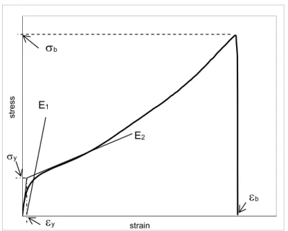
Figure 4.4– Tensile test specimens geometry (in mm). 40 Figure 4.5 - Conventional for evaluating mechanical properties. 41
Figure 4.6 – A two steps TGA characteristic curve of a thermal decomposition reaction. 42 Figure 4.7 - Automated Keithley 487 picoammeter/voltage source. 44 Figure 4.8 – Electrical measurements a) surface electrode configuration; b) volume electrode configuration.
CHAPTER 5: RESULTS AND DISCUSSIONS
Figure 5.1 - FTIR Spectra of neat TPU. 48
Figure 5.2- FTIR Spectra of neat SBS. 49 Figure 5.3- TPU plate with microsized vermiculite (Hoben). 50
Figure 5.4- TPU plate with nanosized nanosilica Aerosil 200. 50 Figure 5.5 - OM images of TPU+HSCB surface cross-section (magnification 10 x). 50
Figure 5.6 - OM images of neat SBS surface cross-section(magnification 20 x). 50 Figure 5.7- OM images of SBS reinforced cut surface. a) SBS+HSCB (magnification 10 x); b) SBS+NC (magnification 20 x); c) SBS+NS (magnification 20 x).
51
Figure 5.8- SEM images of TPU fractured surface (magnification 2000 x, 15kv). 52 Figure 5.9- SEM images of TPU reinforced fractured surface. a) TPU+HSCB
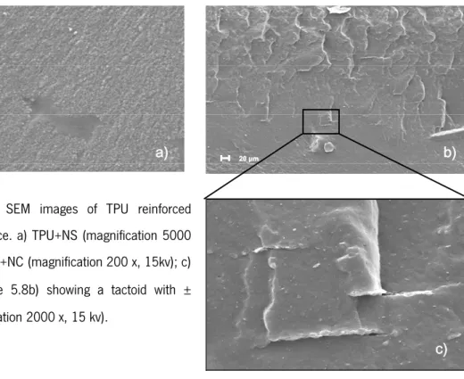
(magnification 20 000 x, 10kv); b) TPU+CNF (magnification 2000 x,15kv); 52 Figure 5.10 - SEM images of TPU reinforced fractured surface. a) TPU+NS (magnification 5000 x,15kv); b) TPU+NC (magnification 200 x, 15kv); c) detail of image 5.8b) showing a tactoid with ± 1μm (magnification 2000 x, 15 kv).
52
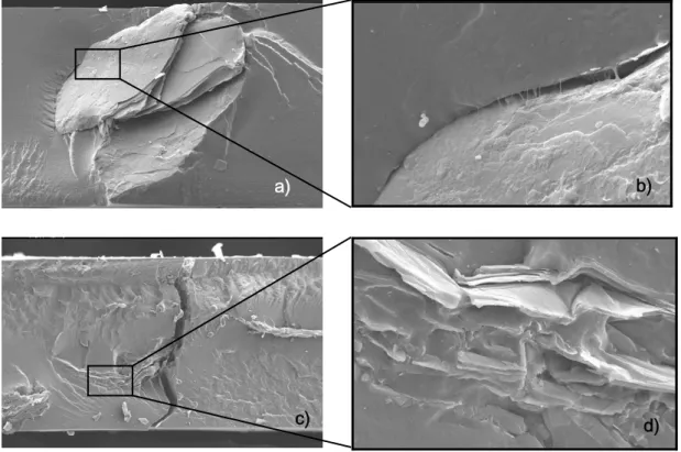
Figure 5.11 - SEM images of TPU reinforced fractured surface. a) TPU+VCC (magnification 140 x, 15kv); b) Larger resolution of detail on figure 27.a) (magnification 2000 x,15kv); c) TPU+VCE (magnification 140x, 15kv); d) Larger resolution of detail on figure 27 c) (magnification 1000x,15kv).
53
Figure 5.12 - SEM images of SBS fractured surface. ( magnification 2000x, 15kv). 54 Figure 5.13 - SEM images of reinforced SBS fractured surface. a) SBS+HSCB
(magnification 5000x, 15kv); b) SBS+NS (magnification 5000x, 15kv); c) SBS+NC (magnification 5000 x, 15kv).
54
Figure 5.14 - SEM images of reinforced SBS fractured surface. a) SBS+VCC (magnification 140x, 15kv); b) SBS+VCC (magnification 2000 x, 15kv); c) SBS+VCE (magnification 140 x, 15kv); d) SBS+VCC (magnification 2000 x, 15kv).
55
Figure 5.15 – Neat and TPEs MFI composites results. 56
Figure 5.16- Stress-strain curves. 57 Figure 5.17 - Normalized stress-strain curves. 57
Figure 5.20 – Variations of yield stress, σy, with incorporation of micro and nanosized
reinforced in TPEs.
59
Figure 5.21 - Variations of yield strain, εy, with incorporation of micro and nanosized
reinforced in TPEs.
60
Figure 5.22 –Variations of stress at break, σb, with incorporation of micro and nanosized
reinforced in TPEs.
61
Figure 5.23 –Variations of strain at break, εb, with incorporation of micro and nanosized
reinforced in TPEs.
61
Figure 5.24- SEM images after tensile tests of fractured surface a)TPU+HSCB (magnification 2000 x,15kv); b)TPU+CNF (magnification 5000 x,15kv).
62
Figure 5.25 - SEM images after tensile tests of fractured surface a)TPU+NS (magnification 5000 x,15kv) ; b) TPU+NC (magnification 2000 x,15kv).
62
Figure 5.26 - Effect of micro- and nanoparticles on the hardness of TPU and SBS. 63
Figure 5.27 – Mass loss a) TPU composites; b) SBS composites. 64 Figure 5.28 - Thermal transitions a) neat and TPU composites; b) neat and SBS
composites (1st melting sweep).
67
Figure 5.29 - Thermal transitions a) neat and TPU composites; b) neat and SBS composites (2nd melting sweep).
68
Figure 5.30 - Thermal Conductivity [W.m-1.k-1] measurements of micro- and
nanoreinforced TPEs.
70
Figure 5.31- Linear Burning Rate of micro- and nanoreinforced TPEs. 71
Figure 5.32- Electrical measurement: a) Surface; b) Volume. 72
APPENDIX III
Figure III.1 – FTIR Spectra of neat and TPU composites Figure III.2 - FTIR Spectra of neat and SBS composites
APPENDIX IV
Figure IV.1 – Yield energy Uy
LIST OF TABLES
CHAPTER 4: MATERIALS, EQUIPMENT AND EXPERIMENTAL METHODS
Table 4.1 – Physical and mechanical properties of the selected TPEs. 34 Table 4.2– Silica nanoparticles detail technical specification. 35 Table 4.3 – Clay nanoparticles detail technical specification. 35 Table 4.4 – High structure carbon black nanoparticles detail technical specification. 35 Table 4.5 - TPU with carbon nanofibers detail technical specification. 36 Table 4.6 - Vermiculite detail technical specification. 36
Table 4.7 - Reinforcement and specimens. 37
CHAPTER 5: RESULTS AND DISCUSSIONS
Table 5.1 - Effect of micro- and nanoparticles on the hardness of TPU and SBS. 63
Table 5.2 - TGA results of neat and filled TPU. 65
Table 5.3- TGA results of neat and filled SBS. 66
Table 5.4 – Neat and filled TPU thermal transitions (1st melting sweep). 67
Table 5.5 - Neat and filled SBS thermal transitions (1st melting sweep). 68
Table 5.6 - Neat and filled TPU thermal transitions (2nd melting sweep). 69
Table 5.7 - Neat and filled SBS thermal transitions (2nd melting sweep). 69
LIST OF SYMBOLS AND ABBREVIATIONS
Latin symbols
b – Thermal absorptance [W.m-2s1]
DTGmax - Temperature of the maximum rate of weight loss (ºC)
E – Modulus of elasticity (Young’s Modulus) (MPa) h – Sample thickness [mm]
nm – nanometers (10 -9 m)
Ø –Diameter (mm) P – Pressure (Pa) T – Temperature (ºC)
Td - Onset temperature of weight loss (ºC)
Tg – Glass Transition (ºC)
Tm – Melting temperature (ºC)
Ub- Energy ate break (J)
Uy – Yield Energy (J) Greek symbols α- Thermal diffusivity [m2.s-1] ΔH – Enthalpy (J/g) Δl – Displacement (mm) ε
εy –.Yield strain (mm/mm)
λ – Stretching ratio (MPa)
λc – Thermal Conductivity [W.m-1.k-1]
μm – micrometer (10-6 m)
ρ – Density (g/cm3)
σb – Stress at break (MPa)
σy – Yield stress (MPa)
г – Thermal resistance [W-1.K.m2]
ABBREVIATIONS
APAM - Alberta Polymer Asymmetric Minimixer CNF – Carbon Nanofiber
CVD - Chemical Vapor Deposition DSC - Differential scanning calorimetry HS – Hard Segments
HSCB – High Structure Carbon Black MFI – Melt flow index (g/10 min) MMT – Montmorillonite
NC- Nanoclay NS – Nanosilica
OM- Optical microscopy
SBS – Styrene-Butadiene-Styrene SEM - Scanning electron microscopy SS – Soft segments
TGA – Thermogravimetric analysis TPE - Thermoplastic Elastomer TPU – Thermoplastic Polyurethane VC – Vermiculite
VCC – Vermiculite crude VCE – Vermiculite exfoliated
CHAPTER 1 INTRODUCTION
1.1. INTRODUCTION
Thermoplastic elastomers, TPEs, are a class of phase separated block-copolymers which consist of soft rubber-segments (conferring its elastic character) and hard glassy or crystallisable chains segments that act as physical crosslink bonds (and impart stiffness and strength). [1,2]During service, TPE behave as elastomers but, in contrast to the classical elastomers, they can be processed by means of the conventional techniques and equipment utilized for all thermoplastics. This peculiarity of TPE is related to their different type of crosslinking bond in their structures. One of the monomers develops the hard, or crystalline, segment that functions as a thermally stable component (which softens and flows under shear, as opposed to the chemical crosslinks between polymeric chains in a conventional, thermosetting rubber); the other monomer develops the soft or amorphous segment, which contributes the rubbery characteristic. A key attribute of most TPEs is the ability to tailor toughness and large strain elasticity by varying the type of monomers, the ratio of hard/soft fractions and the lengths of the hard and soft segments, so the TPEs have been used in many fields. [3]TPEs exhibit an extraordinary combination of reprocessability, elasticity, toughness, low temperature flexibility and strength at relatively high temperatures that make them ideal candidates for engineering applications requiring excellent high mechanical properties; and broad service temperature range.[4] TPE's are used where conventional elastomers cannot provide the range of physical properties needed in the product: Automobile industry; health; shoes soles, including personal care, packaging, sporting goods, houseware, hardware and electronics.[2]TPE materials have the potential to be recyclable since they can be molded, extruded and reused like plastics, but they have typical elastic properties of rubbers which are not recyclable owing to their thermosetting characteristics. They require lower energy costs for processing, are easy of process. TPE are capable of self-assembling by micro- and nanophases segregation processes, allowing the development of different morphologies [5,6]and hence of new properties (e.g., mechanical behavior, chemical resistance).
World consumption of TPE is around 2,1 million of tons in 2006.[7] Global demand for TPEs is forecast to increase 6.2% per year through 2009, reaching 3.1 million metric tons, according to a study made by the Freedonia Group. [8]From this total, 970 thousand tons correspond to rubbers of SBS (styrene-butadiene-styrene) and 470 thousand tons to olefinic thermoplastic rubbers (TPO), followed by polyurethane thermoplastic rubbers (TPU), vulcanized thermoplastic rubbers (TPV), copolyesther rubbers (COPE) and thermoplastic polyamides. As target of great interest in the past decade, TPEs have become a highly sought class of material for replacement of conventional materials in many applications. [9-12] Automobile industry, consumes 600 thousand tons from the total volume. It is
estimated, that approximately 45kg of the car weight corresponds to the TPE, in the more developed markets, Europe and the UnitedStates.
Polymer composites are attractive because of the ability to form new materials with enhanced properties by combining existing components. Synergistic effects also occur, offering new product possibilities. [13]Faced with a growing number of mixtures of polymers with different properties, it is important to study a new class of polymers composites, as a means to further reduce the material cost in competitive markets and achieve a different combination of properties. Modification of TPE through the incorporation of micro- and nanoparticles, embedded in a continuous polymeric matrix known as micro- and nanocomposites. With the incorporation of reinforcing particles, TPEs will have adjustable properties, making them a versatile class of materials more advantageous compared to the thermoplastics and elastomers.
Polymer nanocomposites were first heard in 1990 when Toyota noticed an eminent property enhancement of nylon-6 with the incorporation of a small amount of nanoclay.[14] Such improvements
were attributed to the increase of the interfacial area between polymer matrix and the filler when the clay platelets were individually dispersed. In 1998, the montmorillonite (MMT) was introduced for the first time by Wang and Pinnavaia [15,16] demonstrating mechanical properties improvements. In the last decade, research has demonstrated that composites of polymers with MMT and vermiculites often exhibit unexpected properties derived from synergy coming from both phases, such as improving thermal, mechanical and retardant properties of the material.[17-26]This lead to an increase of interest for the use of other particles in the preparation of nano-composites, [27-39] as TPEs. [36,38,40] Lately, nanosized carbon based fillers have focused the attention and interest of the scientific and technological community[41,42] Materials such as high structure carbon black (HSCB) and carbon nanofibers (CNF) dispersed in the polymeric matrix are used as components of electric conductivity, due to its excellent electric [43-46] and mechanical properties. [47] This makes them an excellent application for protection of electromagnetic interference (EMI), for dissipation of static electricity and for absorption of electromagnetic radiation.[48] Materials with low electrical resitivity have extraordinary economical potential. If theses materials have the ability to conduct electrical current without great resistance, enormous quantities of energies could be economized and applications like computer chips small and
In this work, micro- and nanoparticles were incorporated in TPE matrix by melt blending using a laboratory scale mixer. Within the existing possibilities, two distinct types of TPEs where selected for this study according to their structure and potential application use: i) an amorphous-amorphous BC (e.g., SBS); ii) an amorphous-semicrystalline BC (e.g., TPU). They will allow different structuring capabilities by the incorporation of reinforcing particles. The incorporation of nanoclays (NC) and nanosilicas (NS) aimed to improve TPEs the mechanical properties. HSCB and CNF incorporation was to impart anti-static/electrical and thermal conductivity. NC and crude plus exfoliated vermiculite (VCC and VCE) incorporation aimed to improve flame retardant properties. The relation between morphology and properties were established.
Accomplishing this properties combination resulting from the morphology of nanocomposite is conquer a new opportunity in the conception of polymers responding to stimuli that otherwise wouldn’t be possible.
1.2. REFERENCES
1. Holden G., Milkovich R. - Rubberlike block polymers. U.S. Patent 3265765, 1966.
2. Fakirov S. - Handbook of Condensation Thermoplastic Elastomer. 1st ed. WILEY-VCH, 2005. 3. Honeker C.C., Thomas E.L. - Impact of Morphological Orientation in Determining Mechanical
Properties in Triblock Copolymer Systems. Chemistry of Materials. Vol. 8: nº8:(1996), p. 1702-1714.
4. Aso O., Eguiazábal J.I., Nazábal J. - The influence of surface modification on the structure and properties of a nanosilica filled thermoplastic elastomer. Composites Science and Technology, Vol. 67: nº13 (2007), p. 2854-2863.
5. Abetz V., Goldacker T., Macromol. Rapid Commun. Vol 21(2000), p.16-34.
6. Matsen M.W., BatesF., - Unifying weak- and strong-segregation block copolymer theories, Macromolecules, Vol.29, p.1091; Origins of complex self-assembly in block copolymers, Macromolecules. Vol.29 (1996), p. 7641.
7. Kear K.E., Developments in Thermoplastic Elastomers. Rapra Technology Limited, 2003. 8. http://www.thefreelibrary.com/TPE+demand+to+reach+3.1+mmt+in+2009-a0143305214. 9. Dutta N.K., Bhowmick A.K., Choudhury N.R. - Handbook of Thermoplastic Elastomers. Olagoke,
O., Ed.. Marcel Dekker: New York, 1997. Chapter 15.
10. Bhowmick A.K., De S.K. - Thermoplastic Elastomers from Rubber–Plastic Blends. De, S. K., Bhomwick, A. K., Eds.; Ellis Harwood: New York, 1990. Chapter 1.
11. Utracki L.A., Polymers Engineering Science. Vol. 35: nº 2 (1995).
12. School R.J. - Handbook of Thermoplastic Elastomers. Walker B. M., Rader C. P., Eds.; Van Nostrand Reinhold: New York, 1988. Chapter 9.
13. Breuer O., Sundararaj U., Polymer Composites. Vol. 25:(2004), p. 630.
14. Kojima Y.,Usuki A., Kawasumi M., Fukushima Y., Okada A., Kurauchi T., Kamigaito O. J, Mat. Res. Vol. 8: (1993) p.1185.
15. Zou H., Ran Q., Wu S., Shen J. Polymer Composites. 2008. p.1-5. 16. Wang Z., Pinnavaia T.J.. Chem. Mater. Vol.10 (1998), p.769. 17. Vaia K.H., Giannelis E. P. Macromolecules. Vol.30: (1997), p. 8000.
18. Gârea S. A., Iovu H., Bulearca A. Polymer Testing. Vol. 27 (2008), p.100–113. 19. Cataldo F. Wiley Interscience. Vol. 247(2007), p. 67–77.
22. Kornman X., R.T., Mulhaupt R., Finter J., Berglund L. A. Polymer Engineering Science. Vol. 42 (1992), p.1815.
23. Shelley J. S., Matter P.T., DeVries K. L. Polymer. Vol. 42 (2001), p.5849.
24. Kashiwagia T., Harris Jr R.H., Zhang X., Briber R. M., Cipriano B. H.,. Raghavan S. R, Awad W. H., Shields J. R. Polymer. Vol. 45 (2004), p.881.
25. Xu Y., Hoa S.V., Composites Science and Technology. Vol.68 (2008), p.854–861.
26. Kroto H.W., Heath J. R., OBrien S. C., Curl R. F., Smalley R. E. Nature. 1985: p. 318, 162. 27. Rayneud E., Jouen T., Ganthier C., Vigier G., Varlet J. Polymer , 42, 8759 . 2001.
28. Hambir S.,Bulakh N., Kodgire P., Kalgaonkar R., Jog J.P. Journal Polymer Science Part B, Vol. 39 (2001), p.446 17. Ma J., Qi Z., Hu Y. Journal of Applied Polymer Science. Vol. 82 (2001), p. 3611.
29. Ma J.,Qi Z., Hu Y. J App Polym Sci. Vol. 82 (2001), p.3611.
30. Kawasumi M., Hasegawa N., Kato M., Usuki A., Okada A. Macromolecules. Vol.30 (1997), p.6333.
31. Godgire P., Kalgaonkar R., Hambir S., Bulakh N., Jog J.P.. Journal of Applied Polymer Science. Vol. 81 (2001), p.1786.
32. Whang M.Q., Rong M. Z., Zeng H. M., Schmitt S., Wetzel B., Friedrich K. Journal of Applied Polymer Science. Vol.80 (2001), p. 2218.
33. Alexandre M., Debois P., Sun T., Garces J. M., Jérôme R.. Polymer. Vol. 43 (2002), p. 2123. 34. Vu Y.T., Mark J.E., Pham L.H., Engelhardt M. Journal of Applied Polymer Science..Vol. 82
(2001), p.1391 .
35. Ma J., Zang S., Qi Z.. Journal of Applied Polymer Science. Vol. 82 (2001), p.1444. 36. Sadhu S., Bhowmick A. K.. Rubber Chemistry and Technology. Vol. 76 (2003), p.0860. 37. Sadhu S., Bhowmick A. K.. Journal of Applied Polymer Science. Vol. 92 (2004), p. 698.
38. Sadhu S., Bhowmick A. K.. Journal Polymer Science: Polymer Physics. Vol. 42 (2004), p.1573. 39. Donnet J.B., Bansa R.C., Wang M.J. - Carbon Black Science and technology. 2 ed. Revised and
extended ed. New York: CRC Press, 1993. 461.
40. Sadhu S., Bhowmick A. K.. Journal of Applied Polymer Science. Vol. 92 (2004), p. 698.
41. Dresselhaus M.S., Dresselhaus G., Eklund P.C.- Science of Fullerenes and Carbon Nanotubes. Academic Press, 1996.
42. Iijima S., Nature.Vol. 56 (1991) p. 354.
44. Feng J., Chan C.M. Polymer Engineering Science. Vol. 43: nº 5 (2003), p.1064-1070.
45. RAMARAJ B. - Electrical and mechanical properties of thermoplastic polyurethane and polytetrafluoroethylene powder composites. Taylor & Francis. Vol.46 (2007), p. 575-578.
46. Bellingen C. V., N.P., Grivei E. - Journal of Vinyl & Additive Technology. (2006), p. 14-18. 47. Frogley M.D., Ravich D., Wagner H. D. - Composites Science and Technology. Vol. 63 (2003),
p. 1647–1654.
CHAPTER 2
LITERATURE REVIEW
Most important preparation methods of polymer composites are reviewed. A basic understanding of the different blending processes and available equipments are mentioned. The selected method is described in detail as well as its usage in dealing with polymer composites. Some fundamentals on morphological aspects and properties of thermoplastic elastomers are provided. Special attention is placed on thermoplastic polyurethane and styrene-butadiene-styrene composites. In order to have control on the level of dispersion of the micro- and nanofillers in a polymer matrix, we need to know the nature of such particles in terms of structure, morphology, texture, and chemistry. In this Chapter, we concentrate on the basic aspects of micro- and nanofillers, namely crude and exfoliated vermiculite, carbon nanofibers, high structure carbon black, nanoclay, nanosilica. A state-of-the-art of type of fillers used and their effects on the TPE properties is presented.
2.1. PROCESSING OF TPE BASED COMPOSITES
The need of reinforcing TPE with micro - and nanosize particles requires appropriate facilities for mixing, for controlling de-agglomeration and dispersion of fillers in polymers matrix. This new reinforcing materials are available in low quantities (few grams) because they are expensive to purchase at such early stages of development. Mixing is an extremely complex process because it can involve different basic operations, such as dispersing particles, wetting solid particles by the matrix, plasticizing, and uniformly distributing the particles to obtain a homogeneous compound.[1] To disperse nanoreinforcements, melt mixing methods are usually preferred due to the versatility of the production facilities. [2]Melt blending involves time and temperature-dependent non-Newtonian materials, and in addition, the flow field is a combination of shear and extensional flow.[3] During the blending process, melting and mixing are the most important and basic processing steps because melting affects the process rate, and mixing determines the morphology [4] In order to incorporate these materials into a new polymer material system, laboratory-scale mixing devices are essential. It is necessary for the mixer to be small enough to deal with tiny amounts of material, yet sufficiently powerful and appropriately designed to exert the shear stress and have the flow patterns essential for obtaining well-dispersed and uniform structures as in an industrial scale equipment [5], with minimize material waste.
There are several miniature mixers commercially available, such as twin-screw extruders, MiniMaxTM,
recirculating screw mixerand internal batch mixers for polymer blends compounding of small grams of material in the range of 1-10 g. However, the final blend morphology in these mixers is coarse, with many large dispersed phase domains existing even after 20 minutes of mixing time. [5] Our goal is to compound polymer blends in small quantities so that we can predict the morphology expected in larger production scale, without consuming large quantities of polymer. therefore it was required a better dispersive mixer.
Sundararaj et all have developed a mini mixer called Alberta Polymer Asymmetric Minimixer (APAM). [5] This mixer has a unique, asymmetric design consisting of a varying clearance between the rotor blade tips and the cup wall, enabling the material to be squeezed, stretched and kneaded in high shear and converging zones. [5,6] Unlike the few other miniature mixing devices that are commercially available, the APAM has a combination of good mixing capability and complex flow modes required for dispersive
minimizing material waste. In a study made by Sundararaj et all comparing the blending results of APAM with the mixers above mentioned, there was evident the superior results of APAM, showing a well-dispersed structure.[3,5,6]For this work a miniature mixer was developed based on APAM.
Figure 2.1 - APAM.[5] Figure 2.2 - Particle tracking and path in the metal cup.[6]
2.2.THERMOPLASTIC ELASTOMER 2.2.1.Thermoplastic polyurethane, TPU
Thermoplastic polyurethane elastomers, belong to the class of TPE that combine the mechanical properties of vulcanized rubber with the processability of thermoplastic polymers. They can be repeatedly melted and processed due to the absence of the chemical networks that normally exist in rubber. TPU are linear segmented block copolymers having hard segments (HS) and soft segments (SS).[7] TPU are based on the exothermic reaction of polyisocyanates with polyol molecules, containing hydroxyl groups. Relatively few basic isocyanates and a range of polyols of different molecular weights and functionalities are used to produce the whole spectrum of polyurethane materials. Two types of diisocyanates are employed in polyurethane preparations, aromatic and aliphatic ones. Most commonly used chemical structures are the aromatic diisocyanates; toluene diisocyanate (TDI), and 4,4’-diphenylmethane diisocyanate (MDI) (Figure 2.3). [7]TPU are usually made from pure MDI which is reacted with a substantially linear polyether or polyester diol [7,8]and with a chain-extending diol of a low molecular weight, such as 1,4-butanediol, (BDO) in either a one-step or a two-step reaction process. [86] The polyester diols are usually the condensation products of adipic acid and one or more simple aliphatic diols ranging from ethylene glycol to 1,6- hexanediol.
Figure 2.3 - Molecular structures of most common industrial isocyanates.
The HS act as crosslinks, inhibiting stress-relaxation and inducing stress-crystallization, which results in higher tensile strength. [9] The SS form an elastomer matrix which accounts for the elastic properties of TPU. [7] At room temperature, the low melting SS are incompatible with the polar high melting HS, which leads to a microphase separation and, consequently, to a polydomain structure. [7]
The HS segregates into a glassy or semicrystalline domain, and the polyol SS form an amorphous or rubbery matrix in which the HS are dispersed. [10,11]With the increase on the level of rigid segments, the TPU generally shows an increment on hardness, accompanied by a higher glass transition temperature. The ratio of thermoplastic or rubber phases determines the nature and properties of the product. The tendency to crystallize of the flexible segments is observed during the low and medium stretching, and this result in an induced crystallization affecting the modulus and strength.
TPU are used in applications where a product requires excellent tear strength, abrasion resistance & flexual fatigue resistance, chemical/oil resistance, low permeability to oils and fuels, resistant to radiation exposure. Mechanical properties of the polyester TPU are generally higher. Additives can improve dimensional stability, heat resistance, reduce friction, or increase flame retardancy or weatherability. Service temperatures range from - 50 ºC to 150 ºC and all have excellent adhesion properties. These materials have generally offer better strength and rigidity properties than conventional thermoset rubbers and their high elasticity confers exceptional dynamic flex properties.
2.2.2.Poly(styrene–butadiene–styrene), SBS
Poly(styrene–butadiene–styrene) rubber, was developed at the beginning of the 1960s. [12-14] A tri-block copolymer, SBS belongs to the group of thermoplastic elastomers made by anionic polymerisation. [15]This material consist of two phase structures, a rigid polystyrene segments giving its durability and soft butadiene segments giving SBS its rubber-like properties. [16,17]Polybutadiene glass transition temperature is around -80ºC and polystyrene around 90ºC.
Figure 2.4 - Chemical structure Styrene-Butadiene-Styrene.
Unlike the repeat unit in a statistical copolymer, the repeat units in a block copolymer are arranged in separate blocks. In SBS rubber, each polymer chain consists of three sections, two outer sections made from styrene monomers and a middle section made from butadiene monomers. Since the different chain blocks are actually immiscible in one another, the styrene blocks phase separate from the butadiene blocks. [18]
SBS behave like elastomeric rubbers at room temperature but when heated can be processed like plastics. Most types of rubber are difficult to process because they are crosslinked. But SBS manage to be rubbery without being crosslinked, making them easy to process into nifty useful shapes. [17] This means it can be heated and re-mold unlike covalently crosslinked elastomers. [18]
With low polystyrene content, the material is elastomeric with the properties of polybutadiene predominating. This gives the material the ability to retain its shape after being stretched. [17,19] SBS exhibit good resistant to low temperature, good permeability, elongation percentage, and outstanding elasticity. [12,13]Commonly used in footwear, adhesives and tire treads food and cosmetics packaging.
Figure 2.5 - (a) Very simple schematic view of the SBS block copolymer molecule. (b) Chemical structure of the polystyrene and polybutadiene sections. Parts formed from styrene monomers (red) and butadiene monomers (blue) are marked. [15]
2.3. MICROPARTICLES
Vermiculite VC, belongs to the phyllosilicate group of minerals, the mineralogical name given to
hydrated laminar magnesium aluminum-iron silicate which resembles mica in appearance [20,21]VC is a 2:1 clay, meaning its crystal lattice consists of one octahedral sheet sandwiched between two opposing tetrahedral sheets. [21] A tetrahedral sheet is composed of corner-linked tetrahedra, whose central ions are Si4+ or Al3+.[21] The octahedral sheet is composed of edge-shared octahedra with Mg2+,
Al3+, or Fe2+. Due to isomorphic substitutions which are Al3+ for Si4+substitution in tetrahedral layers and
Mg2+ or Fe2+ for Al3+ substitution in octahedral layers, VC layers have permanent negative charges. [21]
VC is found in various parts of the world, and is recognized for their excellent intercalation abilities. [22] It is formed by hydration of certain basaltic minerals, and is often found in association with asbestos. T is a safe and inert mineral, characteristically yellowish brown in color. When heated it expands (exfoliates) up to 30 times it original volume. Natural and non toxic mineral that expands with the application of heat, are microsize particles between 0.1 and 100 μm in size. The expansion process is called exfoliation.
Figure 2.6 – Structure of vermiculite- Its chemical composition: 22MgO.5Al2O3.Fe2O3.22SiO2.40H2O. [21]
VC has a medium shrink-swell capacity and is considered a limited-expansion clay. When VC is subjected to fast heating, its interlayer crystalline water transforms into steam and the pressure of steam forces the silicate layers apart from one another in which the K+ ions between the molecular
sheets are replaced by Mg2+ and Fe2+ cations. As a result, expanded VC with a large pore volume, light
and clear, a low bulk of density, and a high heat isolator and sound-proof property; [23] refractory insulation material is obtained. easily handled, odorless, and low-cost material.VC has been used in various industries for over 80 years: construction, agricultural (as fertilizer carrier, adsorbent, etc.), horticultural, and industrial markets(as fire protection, acoustic and thermal insulator, additive in concrete and plaster, packaging material, etc.), and environmental (as adsorbent) applications. [21,24]
The bulk density of crude vermiculite (VCC) is in the range of 640-1120 kg/m³ and exfoliated or expanded vermiculite (VCE) is in the range of 64-160 kg/m³. [20]
2.4. NANOPARTICLES
Nanoparticles are ultrafine particles with nanometer dimensions, about 1 to 100 nm, [25] showing size dependency of the properties of composites. [26] There are different types of nanoparticles made out from very wide variety of materials, regarding their origin commercially availability, dimension and geometry. Normally, microparticle additives require much higher loading levels to achieve similar performance than nanoparticles with low loading levels. This can result in significant weight reductions, coming in wide interest and importance for military and aerospace applications. The nanoparticles can be incorporated in a polymer matrix either during polymerization or by melt compounding forming polymer nanocomposites, depending on the application.
2.4.1.Platelet Shape
2.4.1.1.Montmorillonite, MMT
The significant feature of layered silicates, in comparison to other more commonly used, is their high aspect ratio and their ability to be readily dispersible on a nanometer scale. [27] The essential nanoclay (NC) raw material is MMT a 2-to-1 layered smectite clay mineral with a platelet structure. Individual platelet thicknesses are just one nanometer, but surface dimensions are generally 300 to more than 600 nanometers. Naturally MMT is hydrophilic. Since polymers are generally organaphilic, unmodified NC disperses in polymers with great difficulty. Through clay surface modification, MMT can be made organophilic and, therefore, compatible with conventional organic polymers. [2,28,29] Natural clay, containing an inorganic cation in the interlayer, are hydrophilic. After cation exchange of an inorganic cation to a large organic cation, the clay properties are altered and the material becomes hydrophobic. [22] Surface compatibilization is also known as “intercalation”. Compatibilized NCs disperses readily in polymers. When NCs are dispersed and exfoliated in a polymer matrix, they form a near-molecular blend called a nanocomposite. [30]
Figure 2.7 – Nanoclays dispersion in a polymer matrix.
This special structure of the layers results in an unusually high aspect ratio that makes NCs superior to all other conventional layered fillers. [29] These minerals considerably increase the mechanical and thermal properties of polymers through improving fire resistance by formation of a three-dimensional network, smoke emissions, chemical resistance, surface appearance, improved transparency, electrical conductivity, and barrier properties [31] usually resulting from the synergistic effect between organic and inorganic components. [8] This improvement of the properties may be reached with a very low
The properties of NCs strongly depend on the organic matrix, the nanoparticle, and the way in which they are prepared. [8] [1] The best properties are achieved if the clay is fully exfoliated. Their small size
also results in small inter-platelet distances in a polymer/clay nanocomposite. [31]
Na 1/3(Al 5/3Mg1/3)Si4O10(OH)2
Figure 2.8 - Chemical structure of montmorillonite nanoclays.
In the scope of this work, the platelet-like shape nanoparticles of organo-modified layered silicates, MMT, namely, Nanofil 5 (distearyl-dimethyl-ammonium ion exchanged bentonite, recommended for polyesther based polymers) are supplied by Süd-Chemie AG, Germany. This NC have long chain hydrocarbon, as it is schematically presented in the following.
Figure 2.9 - Chemical functionalization of nanoclays (Nanofil 5).
2.4.2.Spherical Shape
2.4.2.1.Nanosilica, SiO2
Nanosilica (NS) consists on spherical particles having a diameter less than 100 nm. Chemically speaking, they are made of silicon and oxygen atoms. Because their surface properties, particle size and their tendency to aggregate in the organic matrix on account of their high surface energy, it is very difficult to predict the properties of newly prepared nanocomposites.
Although silica was up to now widely used in polymer formulation as additives to master the system Layer thickness is 0.96nm Octahedral Na+ Tetrahedral alumina layer silicate layer
open for new applications. Silica synthesis evolved during last decades from thermal hydrolysis of silane resulting in not easily dispersible aggregated nanoparticles to sol-gel process resulting in well-defined nanoparticles, highly compatible with the targeted matrix. Processes enabling chemically tuned and well integrated particles together with the nanoscale effect are a highway to high performance nanocomposite materials having enhanced mechanical properties and excellent surface properties. [32]
2.4.2.2.High Structure Carbon Black, HSCB
Carbon black is an amorphous form of carbon with a structure similar to disordered graphite [33] that has a high surface area-to-volume ratio produced by incomplete combustion or thermal decomposition of gaseous or liquid hydrocarbons under controlled conditions. [34] [2] When aromatic hydrocarbons are
placed to incomplete combustion of carbon-containing materials, such as oil, fuel oils or gasoline, natural gases, coal, paper, rubber, plastics and waste material at high temperature, their molecules will dissociate through the rupture of C-H bonds. Also contain large quantities of dichloromethane- and toluene extractable materials, and can exhibit an ash content of 50% or more. [34]
Smaller particles have higher inter-aggregate attractive forces (Van der Waals forces), resulting into a high secondary structure and an increased agglomerate size. This also means that the dispersion process requires more energy to separate them. [35] If the aggregates are composed of few prime particles, carbon black is designated a low structure carbon black. A high structure carbon black consists of relatively many prime particles. Because high structure carbon blacks tend to produce larger aggregates, consequently higher electrical conductivity at the same loading of low structure carbon black can be shown. [36,37]
a) b) c)
Figure 2.10 - a) Low structure (individual particles); b) Low structure (low agglomeration); c) High structure (with a high degree of openness and chaining)
2.4.3.Carbon Nanofiber, CNF
Carbon has two well known crystalline forms (diamond and graphite) but it also exists in quasicrystalline and glassy states. As far as fibers technology is concerns graphite is the most important structural form of carbon. The graphite structure consist of hexagonal layers, in which the bonding is covalent and strong (~525kJ/mol); these layers, which are called the basal planes, and they are stacked in an ABAB---- sequence, as shown in Figure 2.11, and have weak (<10kJ/mol) inter-layer bonds. The properties of graphite are very anisotropic. The theoretical elastic modulus of graphite is approximately 1000 GPa in the basal plane and only 35 GPa in the c-direction perpendicular to these planes. [38]
Figure 2.11- Crystal structure of graphite.
Graphite sublimes at 3700ºC but starts to oxidize in air at around 500ºC; carbon fibers can however be used at temperatures exceeding 2500ºC if protected from oxygen. Carbon is a good electrical conductor. [38]
CNFs are an important class of graphite-related materials produced from the catalytic decomposition of hydrocarbon gases or carbon monoxide over selected metal particles that include iron, cobalt, nickel, and some of their alloys at temperatures over the range 400±1000°C. This process is termed Catalytic Chemical Vapor Deposition. CNFs are composed of 90 % by weight of elemental carbon and the rest is made various elements mainly oxygen and hydrogen. Different types of defects are present on the surface such as vacancies, dislocations, edges and steps. [39] CNFs have extraordinary mechanical, electrical, and thermal properties and their combination with polymers offers properties improvement breeding a new composite material with promising scientific enhancement.
of the graphitic layers with respect to the fiber axis. CNF composites reaches percolation threshold at only a few volume or weight percents of CNFs, markedly lower than metal particles or carbon black due to high aspect ratio and nanoscale size allowing CNFs to form conductive networks much more efficiently, [40-42] suitable for electrical conductive components, antistatic, electrostatically dissipative, and electromagnetic shielding and sensor applications.
2.5. STATE-OF-THE-ART
It has been long since the first introduction of reinforced polymers into engineering practices, and they have found a prominence place among common materials. There use in various applications requires not only good mechanical properties as well as processing facilities. Their application in new areas, means that other properties must be developed tomeet the desired functionality without affecting the polymer properties. In nanoparticles based polymer composites, physical bonding between filler and matrix is very critical for producing a high performance composite. [39] A prerequisite for a good polymer-nanofiller composite is to have an adequate interfacial adhesion between the inorganic and the organic material. The extent of interfacial contact depends on contact angle and viscosity behaviour of the nanocomposite. [39] The type of filler, their dispersion, their incorporation level, determines mechanical and thermal properties, and is fire behavior of the final composite system, as well as the electrical resistivity. [41,43-54]
In recent years, TPE nanocomposites, long have erne the interest of scientific community showing improved performance and leading to a number of changes in physical properties, due to incorporated fillers high surface area and significant aspect ratios. [55-57]In particular, TPEs have been filled with several nanoparticles, such as NC, NS, HSCB, CNF, in order to improve properties like heat resistance, mechanical properties, anti-static/electrical properties, etc. and the achievement of multifunctional behaviour.
Polymer nanocomposites can be prepared using different methods, including in-situ polymerization, solution processing and melt mixing [58,59] Melt mixing is the preferred method because it is environmentally benign and it is compatible with current industrial processes. [58-60] However, it is difficult to mix [61] homogeneously material such as nanoparticles into a polymer matrix due is natures and because of the existence of synthesis-induced entangled aggregates and the high van der Waals
In the last years, a huge research effort has been allocated to study the reinforced thermoplastics. [63,64] Researchers have found the useful advantage of using NC for TPEs properties enhancement. The first report on the use of NC with elastomeric polyurethane was from Wang and Pinnavaia in 1998. [65] These nanocomposites showed significant improvement in tensile strength and tensile modulus, although the clay particles remained mostly in intercalated states. Volker Altstadt et. al [66] showed improvement of the mechanical properties and creep resistance of SBS block copolymers also by NC incorporation. J. Shen at al. [67]have study TPU filled with MMT by melt blending and observed that NC can also improve TPU thermal stability. [67][3] Wang and Pinnavaia [65] compared TGA measurements
of intercalated and exfoliated organically modified magadiite nanocomposites and observed that the exfoliated nanocomposite showed thermal improvements. Other studies have shown that the introduction of these particles reduces heat release and improve the fire retardancy. [68]
Same mechanical improvement was observed with the use of NS. Wei-Dian Shen et al. Study the properties of TPU/silica (5% to 20% of incorporation) and shown that the incorporation of a small amount of NS increased the hardness, abrasion resistance, and tensile properties of the polymers, but, these mechanical properties could be worsened at higher NS contents. [69]The increase loading percentage may reduce some of the properties TPE. There is a limit amount of incorporation without injuring their mechanical and thermal properties maintaining a desired processability. Similar results have been reposted by Gupta et al. [70] These limitations encourages researchers to further study the application of this reinforce particles on TPE. [71] But it is still needed to understand them better, according to the microstructure / morphology of the material.
No publications were found, by using with crude and exfoliated vermiculite (VCC and VCE).
Polymers characteristically have a very high electrical resistance. [71] When conductive grades are required, base polymers are modified to prevent unwanted accumulation of charge or a conductive pathway.A part of developed work conducted on carbon composites is motivated by the potential of these fillers in TPE properties improvement, making them attractive and of critical importance for the integration in a wide range of high performance applications, e.g., aerospace structural components, heat exchangers, heat sinks, [73,74] sensors and active electrodes. [75]
In the last few years some systematic studies of the thermo-physical [76] and electrical properties [77] of composites has been published. Carbon materials also have great potential to be economically important for thermal management as observed by Zhou et al.. [78] Carbon nanofillers like HSCB and CNF are excellent candidates for multi-functional nano-reinforcing for TPEs because of their high
strength, modulus, high thermal conductivity (higher than copper and silver suitable for thermal management applications), excellent electrical capacity, and thermal stability. Vaia et al [79,80] have evaluated CNFs as TPE reinforcing agents. They observed that low amounts of CNF (1 to 5% of incorporation) lead to TPU mechanical and electrical property improvements
The electrical properties of a composite are determines by the volume fraction of the conductive filler, structure properties, orientation in the matrix, porosity and mixing conditions as observed by Khastgir et al. [81-83] when a study SBS filled with carbon black electrical and mechanical behavior. Homer et al. [76] observed that electrical properties of a composite also depends on the physico-chemical properties of both polymer and filler, such as particle size, shape, porosity, surface area, e.g., smaller and spherical particles or fibers and longer particle affect differently, as well as the composite processing conditions, such as temperature, etc.
For a conductor-filled polymer to be electrically conductive, the filler particles must either touch to form conductive paths, [41] or be sufficiently close to each other to enable conductance via ‘‘tunneling effect’’ as observed by Sheng et al.. [84,85] This is usually defined as the percolation transition, characterised by a sharp drop in the electrical resistivity and the critical weight or volume fraction of filler is the threshold dividing the composite into insulator and conductor. [76]
2.6. REFERENCES
1. Nortey N.O. Int Polym Process. Vol.16 (2001), p. 87.
2. Aso O., Eguiazábal J.I., Nazábal J. - The influence of surface modification on the structure and properties of a nanosilica filled thermoplastic elastomer. Composites Science and Technology. Vol.67: nº 13 (2007), p. 2854-2863.
3. Lin B., Sundararaj U., Guegan P. - Effect of Mixing Protocol on Compatibilized Polymer Blend Morphology. Polymer Engineering and Science. Vol.46: nº5 (2006), p. 691-702.
4. Grulke E.A. - Polymer Processing Engineering, Prentice-Hall. New Jersey,1994.
5. Breuer O., Sundararaj U., Toogood R. W. - The Design and Performance of a New miniature mixer for specialty polymer blends and nanocomposites. Polymer Engineering and Science. Vol.44: nº5 (2004).
6. Breuer O., Chen H., Lin B., Sundararaj U. - Simulation and Visualization of flow in new miniature mixer for multiphase polymer systems,. Journal of applied polymer science. Vol.97 (2005), p.136-142.
7. Frick A., Rochman A. - Characterization of TPU elastomers by thermal analysis (DSC). Polymer Testing. Vol. 23: nº4 (2004), p. 413-417.
8. Ciobanu C., Constantin X.H., Cascaval N., Guo F., Rosu D., Ignat L., Moroi G. - Influence of urethane group on properties of crosslinked polyurethane elastomers. Journal of Applied Polymer Science. Vol.87: nº11 (2003), p. 1858-1867.
9. Wilkes C.E., Yusek C. S. - Investigation of domain structure in urethane elastomers by X-ray and thermal methods. Journal of Macromolecular Science and Physics. B7, (1973), p.157-175. 10. Oertel G. Polyurethane Handbook. 2nd ed. New York: Hanser,chapter 2, 1993 p. 7. .
11. Navarro-Bañón V., J.V.-B., Vázquez P., Martín-Martínez J. M. - Interactions in Nanosilica-Polyurethane Composites Evidenced by Plate-Plate Rheology and DMTA. Macromolecular Symposia. Vol. 221: nº1 (2005), p. 1-10.
12. Honeker C.C., Thomas E.L. - Impact of Morphological Orientation in Determining Mechanical Properties in Triblock Copolymer Systems. Chemistry of Materials. Vol.8: nº8 (1996), p. 1702-1714.
13. Chen Z., Gong K. - Preparation and dynamic mechanical properties of poly(styrene-<I>b</I>-butadiene)-modified clay nanocomposites. Journal of Applied Polymer Science. Vol. 84: nº8 (2002), p. 1499-1503.
14. Holden G, Leggen N.R., Quirk R.P., Schroeder H.E. (Eds). - Thermoplastic Elastomers, 2nd ed.
Hanser: New York, 1996.
15. http://www.azonano.com/Details.asp?ArticleID=2076 16. www.distrupol.com 17. http://pslc.ws/macrogcss/sbs.html 18. http://membership.acs.org/C/Chicago/statefair/CD-2007/Chemmatters/2007_4_tg.pdf 19. www.wikipedia.org. 20. http://www.vermiculite.org/aboutvermiculite.htm
21. Duman O., Tunç S. - Electrokinetic Properties of Vermiculite and Expanded Vermiculite: Effects of pH, Clay Concentration and Mono- and Multivalent Electrolytes. Separation Science and Technology. Vol. 43: nº14 (2008), p. 3755 - 3776.
22. Martynková G. S.,Valášková M., Šupová M. - Organo-vermiculite structure ordering after PVAc introduction. Physica Status Solidi(a). Vol. 204: nº6 (2007), p. 1870-1875.
23. Gordeeva L.G., Moroz E.N., Rudina N.A., Aristov Y.I. - Formation of porous vermiculite structure in the course of swelling. Russ. Journal of Applied Chem. Vol. 75: nº357 (2002).
24. http://www.palabora.com.
25. http://www.chm.bris.ac.uk/webprojects2002/etan/Webpages/.
26. Gangopadhyay R., De, A. - Conducting Polymer Nanocomposites: A Brief Overview. Chem. Mater. Vol.12 (2000), p. 608.
27. Becker O., Simon G.P. - Epoxy layered silicate nanocomposite. ed. Springer. Advance Polymer Science. Berlin Heidelberg, Vol. 179 (2005).
28. Petrovi Z.S, Zavargo Z., Flyn J.H., Macknight W.J. - Thermal degradation of segmented polyurethanes. Journal of Applied Polymer Science. Vol.51: nº6 (1994), p. 1087-1095.
29. www.sud-chemie.com.
30. http://www.nanocor.com/nano_struct.asp.
31. Patil N.V. - Nanoclays make polymers stronger: polymer clay nanocomposites considerably increase the mechanical and thermal properties of polymers. Advanced Materials & Processes. December 1, 2005. p. 39-40.
32. http://becomeananoist.com/index.php?Nanosilica.
35. Medalia A.I. - Electrical Conduction in Carbon Black Composites. Rubber Chemistry Technology. Vol. 59 (1986), p. 432.
36. Carmona F. - Conducting filled polymers. Elsevier. Vo. 157: nº 1 (1989), p. 461-469.
37. Balberg I. - Tunneling and nonuniversal conductivity in composite materials. Physical Review Letters Vol. 59: nº12 (1987), p. 1305.
38. Matthews F.L., Rawlings R.D. - Composite materials: Engineering and science. Chapman &Hall, 1 st. Ed., 1994.
39. Ehrburger P., Vix-Guterl C. - Surface Properties of Carbons for Advanced Carbon-based Composites, In: Design and Control of Structure of Advanced Carbon Materials for Enhanced Performance, Yardim, M. F., Ed.; Kluwer Academic Publishers, Netherlands: Netherlands, 2001.
40. Celzard A., McRae E., Deleuze C., Dufort M., Furdin G., Marêché J. F. - Critical concentration in percolating systems containing a high-aspect-ratio filler. Physical Review B. Vol.53: nº10 (1996), p. 6209.
41. Vu Y.T., Mark J.E., Pham L.H., Engelhardt M. - Journal Applied Polymer Science. Vol. 82 (2001), p.1391 .
42. Sandler J., Shaffer M. S. P., Prasse T., Bauhofer W., Schulte K., Windle A. H. - Development of a dispersion process for carbon nanotubes in an epoxy matrix and the resulting electrical properties. Polymer Engineering and Science. Vol. 40 (1999), p. 5967-5971.
43. Kawasumi M., Hasegawa N., Kato M., Usuki A., Okada, A. Macromolecules. Vol. 30 (1997), p.6333.
44. Godgire P., Kalgaonkar R., Hambir S., Bulakh N., Jog J.P. Journal of Applied Polymer Science. Vol. 81 (2001), p.1786.
45. Whang M.Q., Rong M.Z., Zeng H.M., Schmitt S., Wetzel B., Friedrich K. Journal of Applied Polymer Science. Vol. 80 (2001), p. 2218.
46. Alexandre M., Debois P., Sun T., Garces J.M., Jérôme R. Polymer. Vol. 43 (2002),p. 2123. 47. Ma J., Zhang S., Qi Z., Journal of Applied Polymer Science. Vol. 82 (2001), p.1444. 48. Sadhu, S., Bhowmick A.K, Journal of Applied Polymer Science. Vol.92 (2004), p. 698.
49. Sadhu, S., Bhowmick A.K. Journal Polymer Science: Polymer Physics. Vol. 42 (2004), p.1573. 50. Sadhu, S., Bhowmick A.K. Rubber Chemistry Technology. Vol.76 (2003), p. 0860.
51. Donnet J.B., Bansal R.C., Wang M.J. - Carbon Black—Science and Technology, 2nd Ed. Marcel
52. Dresselhaus M.S., Dresselhaus G., Eklund P.C. - Science of Fullerenes and Carbon Nanotubes. Academic Press, 1996.
53. lijima S. Nature. Vol. 56 (1991) p. 354.
54. Strumpler R., Glatz-Reichenbach J. - Conducting Polymer Composites, J. Electroceramics. Vol.3: nº4 (1999), p.329-346.
55. Becker O., Simon G.P. - Epoxy Layered Silicate Nanocomposites. Advances in polymer science. Vol. 179 (2005), p. 226 (0065-3195 ).
56. Holister P., Weener J.W., Vas C. R., Harper T. Nanoparticles Cientifica. Technology White papers. nº3, 2003.
57. Becker O., Simon G.P. - Epoxy Layered Silicate Nanocomposites. Advances in polymer science. Vol. 179 (2005), p. 226 (0065-3195 ).
58. Breuer O., Sundararaj U. Polymer Composites. Vol.25 (2004), p.630.
59. Lin B., Sundararaj U., Guegan P. - Effect of mixing protocol on compatibilized polymer blend morphology. Polymer Engineering & Science.Vol. 46: nº5 (2006), p. 691-702.
60. Ray S.S., Okamoto M. Prog. Polymer Science. Vol. 28 (2003), p.1539.
61. Siriwardena S., Ismail H., Ishiaku U. S., Perera M. C. S. Journal of Applied Polymer Science. Vol. 85 (2002), p.438–453.
62. Potschke P., Bhattacharyya A. R., Janke A., Goering H. Compos. Interfaces. Vol. 10 (2003), p.389.
63. Pal P.K., De S.K. Rubber Chemistry and Technology. Vol. 56 (1983), p. 737.
64. Rozman H.D., Peng G.B., Ishak Z.A.M. Journal of Applied Polymer Science. Vol.70 (1998), p.2647.
65. Wang Z., Pinnavaia T.J. Chem. Mater., Vol.10 (1998), p.769.
66. Lietz S., Yang J-L., Bosch E., Sandler J.K.W., Zhang Z., Altstädt V.- Improvement of the Mechanical Properties and Creep Resistance of SBS Block Copolymers by Nanoclay Fillers. Macromolecular Materials and Engineering. Vol. 292: nº1 (2007), p. 23-32.
67. Zou H., Ran Q., Wu S., Shen J. Polymer Composites. 2008,p. 1-5.
68. Wang Z-Y., Han E.-H., Kei W. - Fire-resistant effect of nanoclay on intumescent nanocomposite coatings. Journal of Applied Polymer Science. Vol.103: nº3 (2007), p. 1681-1689.
polyester-71. Knite M., Teteris V., Aulika I., Kabelka H., Fuith A. Advance. Engineering Material. Vol. 6: nº9(2004), p. 746-749.
72. BLYTHE A.R. - Electrical resistivity measurements of polymer materials. Polymer testing. Vol. 4: nº2-4 (1984), p. 195-209.
73. Biercuk M.J., Llaguno M.C., Radosavljevic M., Hyun J.K., Johnson A.T., Fischer J.E. -Carbon nanotube composites for thermal management. Applied Physics Letters. Vol. 80 (2002), p. 2767.
74. Benedict L.X., Vincent C.H., Steven L.G., Marvin C.L. - Static conductivity and superconductivity of carbon nanotubes: Relations between tubes and sheets. Physical Review B, Vol. 52: nº 20 (1995), p. 14935.
75. Gutiérrez M. P., Li H., Patton J. - Thin Film Surface Resistivity. Materials Engineering, Proc. Inst. Radio Engrs. Vol. 42 (2002), p. 420.
76. Homer M.L., Lim, J.R., Manatt, K., Kisor A., Manfreda, A.M., Lara L., Jewell A.D., Yen S.P.S., Zhou H., Shevade A.V., Ryan M.A.- Temperature effects on polymer-carbon composite sensors: Evaluating the role of polymer molecular weight and carbon loading in Sensors. Proceedings of IEEE. 2003.
77. Holliday L., Kelly A., F.R.S., Polymer engineering composites. Applied Science Publishers Ltd. 1977, London.
78. Zhou Y., Jeelani S., Eranezhuth B. - Improvement in thermal, mechanical and electric properties of multi-wall carbon nanotube reinforced epoxy and carbon/epoxy composite. eXPRESS Polymer Letters. Vol.2 (2008), p. 40–48.
79. Powers D.S., Vaia, R.A., Koerner H., Serres J., Mirau P.A. - NMR Characterization of Low Hard Segment Thermoplastic Polyurethane/Carbon Nanofiber Composites. Macromolecules. Vol. 41: nº12 (2008), p. 4290-4295.
80. Lai S.-M., Wang C.K., Shen H. F. - Properties and preparation of thermoplastic polyurethane/silica hybrid using sol-gel process. Journal of Applied Polymer Science. Vol. 97: nº3 (2005), p. 1316-1325.
81. Sau K.P., Chaki T.K., Khastgir D. - The change in conductivity of a rubber-carbon black composite subjected to different modes of pre-strain. Composites Part A: Applied Science and Manufacturing. Vol. 29: nº4 (1998), p. 363-370.
82. Leyva M.E., Barra G.M.O., Moreira A.C.F., Soares B.G., Khastgir D. - Electric, dielectric, and dynamic mechanical behavior of carbon black/styrene-butadiene-styrene composites. Journal of
83. Mohanraj G.T., Chaki T. K., Chakraborty A., Khastgir D. - Effect of some service conditions on the electrical resistivity of conductive styrene-butadiene rubber-carbon black composites. Journal of Applied Polymer Science, 2004. 92(4): p. 2179-2188.
84. Simmons GJ. - Generalized formula for electric tunnel effect between similar electrodes separated by a thin insulating film. Journal of Applied Physics. Vol. 34 (1963), p. 1793–803. 85. Sheng P., Sichel E.K., Gittleman JL. - Fluctuation-induced tunneling conduction in
carbonpolyvinylchloride composites. Physics Review Letters. Vol.40, 1978.
86. Randall D., Lee S., Woods G. - The polyurethanes book. Distributed by J. Wiley: New York, 2002.
CHAPTER 3 MOTIVATION AND OBJECTIVES
The motivation, main objectives of this research work, as well as the specific tasks are presented. At the end of the chapter a flow chart illustrates the experimental sequence used in this thesis.
3.1. MOTIVATION
The information provided in the preceding chapters has demonstrated that many investigations have confirmed the improved properties resulting from the addition of micro- and nanosized particles in many conventional thermoplastics and elastomers. From among the numerous advantages offered by micro- and nano-reinforcement, the possibility of achieving multifunction and enhanced properties needs to be still explored. With the addition of reinforcing particles, TPEs allow an adjustment of their properties, making them a versatile class of materials more advantageous compared to the thermoplastics and elastomers. Few studies have focus exclusively on exploring the use of micro- and nanoparticles particles for TPE properties and performance reinforcement. It is well known that nanocomposites require low amounts of nanofillers, but most of the publications on reinforced TPE have focus on the use of higher incorporation amounts (superior to 1%wt.[1-6]). Large volume fractions has demonstrated a negative impact in deformability, processibility, surface finish, and limit the ability to maintain desired conductivity at extreme deformations (>100%).
Faced with a growing interest of these composites it is important to study a new class of polymers composites, as a means to further reduce the incorporation percentage, and therefore the material cost.
3.2. OBJECTIVE
Driven by the importance of materials reinforcement (Chapter 1) and based on the research work embodied in this thesis, it is intended to provide a deeper knowledge in the:
-Validation of dispersion ability of the developed laboratory-scale miniature mixer;
-Evaluation of the incorporation effect of the different types of particles (eg. Micrometric and nanometric dimension) on multifunctional behavior, the mechanical, thermal and antistatic properties and TPEs (namely, TPU and SBS) flame behavior;
-Establish a relation between the developed morphology and the reinforced TPEs mechanical properties with different particles.
3.3. WORK PERFORMED
The materials selected for this research work, namely TPU and SBS, will be mixed with low amounts of microsize (crude and exfoliated VC) and nanosize (HSCB, CNF, NS, NC) particles through the following steps:
a) TPEs reinforcement preparation
- Setting the blending condition (temperature, rotation velocity, mixing time, incorporation %); - TPE molded plates preparation;
- Evaluate the dispersion degree (Optical microscopy (OM), Scanning electron microscopy (SEM)); - Cut tensile test specimens for testing.
b) Morphological characterization
- TPEs functional groups identification (Fourier transform infrared spectroscopy);
- Evaluation of the agglomeration, dispersion and particles adhesion in the matrix through microscopic techniques (OM, SEM);
- Particles/aggregate dimension evaluation (OM, SEM);
- Analysis of the fractured surface and morphological characterization of the deformed material; c) Properties characterization
- Composites Melt Flow Index measurement.
- Mechanical characterization (Tensile tests, hardness);
- Thermal characterization (Thermagravimetric analysis, Scanning electron microscopy, thermal conductivity);
- Flame behavior characterization (flame tests); - Electrical characterization (electrical resistivity);
Figure 3.1 - Experimental sequence.
TPE
TPU SBS
Blending conditions settlement
Characterization
Preliminary analysis of the TPE specimens


![Table 4.6 - Vermiculite detail technical specification. [5,6]](https://thumb-eu.123doks.com/thumbv2/123dok_br/17954488.853977/51.892.116.817.515.623/table-vermiculite-detail-technical-specification.webp)