Study of the Laser Metal Deposition (LMD)
technology in the automotive industry
Master degree in Automotive Engeneering
Francisco Miguel Quaresma Ramalho
Study of the Laser Metal Deposition (LMD)
technology, in the automotive industry
Master degree in Automotive Engeneering
Francisco Miguel Quaresma Ramalho
Project under the supervision of Professor Maria Leopoldina Alves, and Professor Mário Simões Correia
This project report is original, made only for this purpose, and all authors whose studies and publications were used to complete it are duly acknowledged.
Partial reproduction of this document is authorized, provided that the author is explicitly mentioned, as well as the study cycle, i.e., Master degree in Automotive Engineering, 2018/2019 academic year, of the School of Technology and Management of the Polytechnic Institute of Leiria, and the date of the public presentation of this work.
I am dedicating this thesis to my mother and father, who have always loved me, believed in me, and provided me with the necessary conditions so I could go as far as I wished in life. I would also like to dedicate this thesis to my maternal grandparents, who sadly are no longer among us, but who always supported and loved me for as long as they were with me.
All of their words of motivation and care push me towards my goals every day, and will continue doing so.
During the execution of this project, I have received a large amount of assistance and guidance, which helped me go through every obstacle that arose during this period.
Firstly, I would like to thank IK4-Tekniker, whom has made themselves available, to hear the guidelines of the project, before it had even started, and readily made several LMD produced components available to me, so I could conduct the study that was designed. Additionally, I would like to thank Trumpf, whom has also made themselves available for a talk in which it was possible to obtain valuable information about the technology that was studied in this project.
I would also like to thank, Dr. Amilcar Ramalho, and Dr. Luis Vilhena, as well as the ICEMS of the University of Coimbra, which provided their expertise as well as their equipment on the execution of the friction and wear tests, as well as the impulse excitation of vibration test.
Adding to both the companies that helped, I would like to thank my supervisor, Dr. Maria Leopoldina Alves, with whom this project started, as a smaller study, ending up evolving into the present project. Her expertise and guidance were invaluable, for both the theoretical research as well as for the methodology.
I would also like to thank, my second supervisor, Dr. Mário Correia, who despite only joining the project in later date, also ended up providing me with his expertise and guidance, for the theoretical research and also for the methodology.
I would also like to thank Eng. Fernanda Carvalho, who as provided me with guidance on the experimental part of the project, assisting and providing her expertise on the matter.
The last few decades in the automotive industry have been marked by a heavy concern with the environment, saving energy and reducing material wastage, while aiming to maintain good mechanical properties, essential in the components usage.
Additive manufacturing (AM) techniques present themselves as a viable option in the matter, with Laser Metal Deposition (LMD), rising as one of the most promising techniques within this category, capable of producing near-net shape components, with a layer upon layer construction of three-dimensional solid parts from a 3D CAD model, with good mechanical properties and acceptable surface finishing.
Laser Metal Deposition is a relatively recent technique, which is made noticeable by the lack of clarification about the influence of several parameters in the final component’s characteristics, ultimately leading to a scarce availability of the process in the market. This paper aims to clarify and evaluate, how LMD produced parts can suit the automotive industry, by measuring and analysing their behaviour under several mechanical tests.
Originality and Copyright ... iii
Dedication ... iv
Acknowledgments ... v
Abstract ... vi
List of Figures ... ix
List of Tables ... xii
List of Abbreviations and Acronyms ... xiv
Introduction ... 1
1.1. Objectives ... 2
1.2. Structure of the project ... 2
Theoretical framework... 4
2.1. Metal additive manufacturing processes ... 4
2.2. Laser metal deposition ... 8
2.2.1. Powder and wire LMD ... 12
2.2.2. Metallic wire ... 14
2.2.3. Metallic powder ... 15
2.2.4. Laser technology... 16
Materials and methodology ... 19
3.1. Experimental LMD components ... 19 3.2. Component preparation ... 25 3.3. Methodology ... 27 3.3.1. Surface preparation ... 29 3.3.2. Microhardness test ... 30 3.3.3. Density test ... 33
3.3.4. Optical microscopy test ... 34
3.3.5. Impulse excitation of vibration test ... 37
3.3.6. Friction and Wear test... 38
Results and discussion ... 41
4.3. Optical microscopy test ... 46
4.4. Impulse excitation of vibration test ... 48
4.5. Friction and Wear test ... 51
Conclusion ... 63
Future work ... 66
Figure 1 - Manufacturing cost variation per manufactured number of parts [10]. ... 7
Figure 2 - Illustration of an LMD deposition process [18]. ... 10
Figure 3 - Graphical representation of the molten pool area [17]. ... 10
Figure 4 - Schematic representation of layer deposition in LMD technology [16]. ... 10
Figure 5 - LMD deposition process, with robotic control, application [20]. ... 12
Figure 6 - Schematic representation of wire drawing [27]. ... 14
Figure 7 - Schematic representation of the first designed ruby laser [36]. ... 17
Figure 8 - Components produced by IK4-Teknikerand provided for analysis [37]. ... 19
Figure 9 - SEM photomicrographs of Metco 42C metallic powder [40]. ... 20
Figure 10 - Component P1 (left) and P2 (right) originally provided by IK4-Tekniker. ... 22
Figure 11 - Component P3 (left) and P4 (right) originally provided by IK4-Tekniker. ... 22
Figure 12 - Component P5 originally provided by IK4-Tekniker. ... 23
Figure 13 - Deposition strategy for the base, which is repeated on the z-axis, overlaying layers, creating the final powder components [39]. ... 23
Figure 14 - Component W1 (left) and W2 (right) originally provided by IK4-Tekniker. ... 24
Figure 15 - Component W3 (left) and W4 (right) originally provided by IK4-Tekniker. ... 24
Figure 16 - Component W5 originally provided by IK4-Tekniker. ... 24
Figure 17 - Deposition strategy for the base, which is repeated on the z-axis, overlaying layers, creating the final wire components [39]. ... 25
Figure 18 - The equipment Struers Labotom-3 used to separate the deposited material from the substrate. .. 26
Figure 19 - Representation of a wire (left) and powder (right) component after the separation between the substrate and the deposited material. ... 26
Figure 20 - Graphic representation of the conducted mechanical tests, in a timeline... 28
Figure 21 - Surface polishing preparation process. ... 29
Figure 22 - The Struers RotoPol-21 equipment, the polishing machine used to prepare the components for microhardness testing. ... 30
Figure 23 - Representation of a bad surface finish, with too many scratching, due to bad polishing. ... 31
Figure 24 - Vickers hardness test [44]. ... 32
Figure 27 - Density testing apparatus. ... 34
Figure 28 - Detail of the cut components for density testing. ... 34
Figure 29 - Detail of the small pieces cut from components W2 (on the left) and P2 (on the right) for the optical microscopy test. ... 35
Figure 30 - Detail of the specimen mirrored surface finish. ... 36
Figure 31 - Mechanical vibration test apparatus [48]. ... 38
Figure 32 - Wear testing apparatus [51]. ... 39
Figure 33 - Microhardness test results for components P1 (left) and P2 (right). ... 41
Figure 34 - Microhardness test results for components P3 (left) and P4 (right). ... 41
Figure 35 - Microhardness test results for components P5 (left) and W2 (right). ... 41
Figure 36 - Graphical representation of the relation between the deposition height and the microhardness tendency line slope (left) and standard deviation (right). ... 43
Figure 37 - Identifiable gaps on component W2, after performing a vertical cut. ... 45
Figure 38 - Identifiable gaps on component W2, after performing a horizontal cut. ... 46
Figure 39 - Single layer disposition (left) and horizontal layer overlap (right) on component P2. ... 46
Figure 40 - Layer disposition, with evidence of possible gap formation on component P2... 47
Figure 41 - Layer disposition on component W2. ... 47
Figure 42 - Component P2 (left) and W2 (right) microstructure. ... 48
Figure 43 - Experimental and analytical response to the impulse excitation of component W2. ... 49
Figure 44 - Vibration spectra of component W2. ... 49
Figure 45 - Vibration spectra of component P2. ... 50
Figure 46 - Component W2 base friction coefficient variation during reciprocating sliding tests. ... 51
Figure 47 - Component W2 top friction coefficient variation during reciprocating sliding tests. ... 52
Figure 48 - Component P2 base friction coefficient variation during reciprocating sliding tests. ... 53
Figure 49 - Component P2 top friction coefficient variation during reciprocating sliding tests. ... 53
Figure 50 - Cross section profiles from the wear tracks on the base part (left) and top part (right) of the W2 component, for 3, 5 and 7 N of normal force. ... 57
Figure 51 - Cross section profiles from the wear tracks on the base part (left) and top part (right) of the P2 component, for 3, 5 and 7 N of normal force. ... 57
Figure 54 - Comparison between the base and top cross section area of the wear profile, on W2 (left) and P2 (right) specimens. ... 60
Table 1 - Comparison between AM and conventional manufacturing techniques, in industry applications [10].7
Table 2 - DIN C45E typical main mechanical properties [38]. ... 20
Table 3 - Metco 42C (equivalent to AISI 431 Stainless Steel) typical mechanical properties [34]. ... 21
Table 4 - AISI 316L Stainless Steel typical mechanical properties [41]. ... 21
Table 5 - Powder LMD components dimensions (x, y, z). ... 23
Table 6 - Wire LMD components dimensions (x, y, z). ... 25
Table 7 - Chemical composition of the used etchants for component W2 (left) [46] and P2 (right) [47]. ... 36
Table 8 - Zirconium sphere mechanical properties [50]. ... 39
Table 9 - Microhardness test results. ... 42
Table 10 - Density test results. ... 45
Table 11 - Mechanical elastic properties, obtained through impulse excitation of vibration testing, for components W2 and P2. ... 50
Table 12 - Relation between density for components W2 and P2... 50
Table 13 - Wear scars left on the zirconium sphere for component W2. ... 54
Table 14 - Wear scars left on the zirconium sphere for component P2. ... 55
Table 15 - Zirconium sphere wear scars diameters, depth (h) and volume (V) of the wear scars, and wear rate (k) of the component W2. ... 55
Table 16 - Zirconium sphere wear scars diameters, depth (h) and volume (V) of the wear scars, and wear rate (k) of the component P2. ... 56
Table 17 - Point coordinates of the quadratic curves used to represent the wear profile cross section on the W2 specimen base part. ... 58
Table 18 - Point coordinates of the quadratic curves used to represent the wear profile cross section on the W2 specimen top part. ... 58
Table 19 - Point coordinates of the quadratic curves used to represent the wear profile cross section on the P2 specimen base part. ... 59
Table 20 - Point coordinates of the quadratic curves used to represent the wear profile cross section on the P2 specimen top part. ... 59
Table 21 - Wear profile cross section approximate area of specimen W2 base and top parts. ... 59
Table 22 - Wear profile cross section approximate area of specimen P2 base and top parts. ... 59
AM Additive Manufacturing ASTM
CNC
American Society for Testing and Materials Computer Numerical Control
DLF Directed Light Fabrication
EBFFF Electron Beam Free Form Fabrication ESTG School of Technology and Management
LASER Light Amplification by the Stimulated Emission of Radiation LENS Laser Engineered Net Shaping
LMD Laser Metal Deposition
SEM Scanning Electron Microscope
Introduction
European Union regulations are in constant evolution, demanding that car manufacturers have increasingly lower pollutant emissions every year, which ultimately leads manufacturers to invest large amounts of money in research and development, to come up with more efficient and environment-friendly ways of manufacturing their vehicles.
The technical capabilities that brands acquire with this R&D allow them not only to accomplish the restrict regulations, but also to gain a competitive advantage over the contestants in the automotive industry.
The focus of a car-producing brand, in everyday life, is to achieve acceptable quality in its vehicles, conjugating that with a maximum reduction of costs and emissions of pollutants, allowing to accomplish the impositions and still maintain a competitive position in the market.
In this context, additive manufacturing (AM) technologies present themselves as a viable alternative to those which are considered the more conventional manufacturing processes, since they allow waste reduction of raw materials and significant energy savings, as well as a reduction in production time, points that constitute a strong basis, strong enough for further developments to be carried out on this type of technology.
Within these additive manufacturing processes, the LMD (Laser Metal Deposition) technology presents itself as a strong alternative to replace processes of a subtractive nature, once it allows the production of near-net shape metallic components, with good mechanical properties that can satisfy most of the purposes to which they are intended.
The LMD technology presents advantages at an energetic level, reveals low material waste, lower production times when comparing with conventional manufacturing processes and a good reproducibility, factors that make it a strong candidate to take on a role in the automotive industry of the future.
Despite the mentioned advantages of the LMD technology, the majority of automotive brands still have some uncertainty about its applicability to their production lines, due to the fact of it being a relatively recent technology, meaning that the feasibility of its application is still something being studied.
Currently the main applications of LMD technologies are essentially related to coating and repairing processes of new or already existent parts, which allow to obtain surfaces with high hardness and mechanical resistance, meaning that the production of near-net shape components is yet to be applied to production lines, much because of the youthfulness of the process.
The influence that various parameters have in the process, such as power, width and distance to the deposition substrate of the laser beam, and the flow and distance to the deposition substrate of the feed of metallic material, is not yet well defined, with scarce documentation available, highlighting the pertinence of carrying out a study on this topic.
It should be noticed that, as mentioned, the youthfulness of the technology along with its complexity, means that the production of components is still costly. Adding to this, there is also a lack of standardized equipment and material on the market, preventing the process to be applied on a larger scale.
Having the above mentioned in mind, a study to characterize the influence of each parameter on the final product would imply a high number of tests, making it economically demanding, especially taking into account that this study must be performed in a restricted time window. Therefore, combining a more viable economical context to a more restricted time frame, a suitable project can be in fact idealized, starting from the principle that there is a set of optimized parameters that allow the production of model components, allowing to use these to evaluate what are the main mechanical characteristics of these components, which allows to obtain a widespread characterization of what can be expected when using LMD technologies.
1.1. Objectives
This project sets as its main goal, to study the mechanical properties of several LMD components produced with both powder and wire LMD processes, using several deposition heights on the powder LMD components, starting with the available information on the bibliography, and finishing in a place where new information can be achieved in order to either complement or increment the already existent information.
In order to achieve the main goal, it is necessary to firstly, understand how both powder and wire LMD components compare within themselves, in a mechanical behaviour point of view, also analysing how the deposition height affects this comparison.
Secondly, it is necessary to understand, how the mentioned LMD components, compare to components produced with conventional manufacturing techniques, also on a mechanical behaviour point of view.
With the information gathered, while trying to achieve the main goals, a less critical goal, was to try and understand, if LMD produced components are in fact feasible for use on the automotive industry.
1.2. Structure of the project
The project was designed to be presented in this report in several chapters, which represent the order in which the work was developed.
The introductory chapter, is where both the theme and the major goals are presented, creating a clear panorama of what was set to achieve by the end of this project.
The second chapter, “Theoretical framework”, is where the state of the art is analysed, helping to understand how the technology under analysis was born, in what state it is in the present, and where can it go in the future.
The third chapter, “Materials and methodology”, is where a presentation is made of exactly what were the available materials to conduct the study, and also, how the study was
scheduled regarding the mechanical tests and the preparation for them.
The fourth chapter, “Results and discussion”, is where all of the results that were obtained from the mechanical tests were analysed, in order to understand exactly what information can be achieved with this project.
The fifth and final chapter, “Conclusions”, is where all of the information is filtered, presenting only the core conclusions that were taken from the mechanical tests.
Theoretical framework
Laser Metal Deposition is one of the metal additive manufacturing processes currently existent. To better understand how LMD technology was developed, a brief analysis upon the broad category of additive manufacturing (AM), as well as its relationship with metallic materials is important to be performed.
As so, to offer a more detailed overview of the technology under investigation, a few aspects of its basis are shown in this chapter, with a brief look into the history of AM processes, some economic aspects connected with them, their advantages as well as the limitations, the use of metallic materials and finally the main forms that exist nowadays.
2.1. Metal additive manufacturing processes
ASTM International, defines additive manufacturing, as “a process of joining materials to make objects from 3D model data, usually layer upon layer, as opposed to subtractive manufacturing methodologies.” [1], with this definition being applicable not only to metals,
but also to ceramics, polymers, composites and biological systems.
The first attempt to deposit a material in a manual layered build-up dates from 1934, when Anton [2] used combustion reactions, in the form of oxy-fuel welding, to melt a type of metal,
indicating that the early days of AM actually started with metallic materials. However, there were serious accuracy and resolution issues due to the primitiveness of the technology, leading to attempts of enhancing the process used to melt the metal. Even though, these were classified as a primitive form of additive manufacturing, one cannot fully classify them as so.
Despite the fact that AM processes started to be designed using metallic materials, it was not with these that the first big steps of development were made, given that the equipment necessary to achieve the melting of the metallic materials was not available, at least in an efficient level.
Modern additive manufacturing processes were presented by Munz [3] that used
stereolithography models in 1951. Later, in 1968, Swaison [4] had the idea of using a laser
beam to solidify photosensitive polymers. It was only in 1971 that Ciraud [5], presented
research that addressed the use of powder, partially melted by a laser, electron or plasma beam. All this research led to 1981, the year when Housholder [6] first presented “Powder
Laser Sintering” and Kodama [7] published research about the first rapid prototyping system,
with these two being the first true additive manufacturing systems.
However, it was only in 1986 that AM technologies started to be commercialized, with several companies joining the market [8].
At the same time that AM technology entered the market, a more exhaustive research regarding the use of metal within this type of process started to be conducted.
One of the first documented studies that attempted to use metal as a deposit material in AM processes dates from 1986, in the University of Texas, in Austin [9]. Researchers that were
carrying out studies using polymer in the form of powder, to create parts, layer by layer, with the main goal of manufacturing a full component, decided to study how metal would behave under the same conditions. This is believed to be one of the first attempts of metal additive manufacturing in history, in a modern form.
Since then the major part of research is focusing on making the technology more suitable for commercial and industrial use, with efforts being made to improve the properties of the components being produced.
Taking a closer look at the fundamentals for metal additive processes it is possible to understand that there are several aspects that need further improvements and studies. One of the main aspects that is being faced relates to the highly variable thermal cycles that the deposited layers go through, which highly influence the properties of AM produced parts. All in all, this ends up being consider a limitation due to the fact that, to this day, it is relatively unknown how this thermal variance influences the components in a broad variety of materials, because most of the research was conducted with TC4 titanium alloy, with most of the other metallic materials being still under study [10].
Another relevant aspect is related to the reproducibility of parts and properties, since machine-to-machine variance is still relatively high, showing a need to create a more solid way to control these aspects and standardizing it.
However, and taking a broader look into the AM panorama, the scenario is highly positive, with the creation of a committee in 2009 by ASTM specifically for AM technologies, strengthening the importance of this family of manufacturing processes. The mentioned committee, the F42 Committee, has released several standards regarding the technology and the various aspects related to it [10].
All these achievements over history led to a family of technologies capable of competing face to face with the more conventional methods of manufacturing.
AM systems can be taken down and separated into categories, by dividing them by material feed stock, energy source and build volume, amongst other aspects.
There are many types of AM technologies, however, the more relevant ones for this project are, powder bed systems, powder feed systems and lastly wire feed systems [10].
The first type, by no specific order, is the powder bed system. There are two main parts of this system, a powder bed and an energy source. The powder bed is constituted out of the material in which the component will be made and the energy source is usually either a laser or an electron beam. The movement of the energy source over the powder bed, or vice versa,
allows the melting or sintering of the powder into the desired shape. Repeating this action layer by layer will end up in the manufacturing of the full component.
The second type of AM process is the powder feed system. This system is composed by a deposition head in which the powder is fed and melted, allowing its deposition into a surface on which the part is manufactured layer by layer.
The last type of AM processes is the wire feed system. This type of system is similar to the powder feed system, with the main difference being that the deposition material is in the form of a wire. Much like powder feed systems, there is an extruder head into which the wire is fed and then melted allowing its deposition.
Metallic materials are currently use for each of the three types of AM technologies, with some being more suitable to one type then others. However, on the list of most commonly used metals in AM technologies it is possible to find titanium alloys, such as TC4 and titanium aluminides, aluminium alloys, nickel alloys, tool steels, super alloys such as Inconel, and stainless steels such as AISI 316, 316L, 420 and 347.
In terms of economy, the growth that has been registered upon the application of AM processes on the broad variety of industries is truly remarkable.
In 2011, AM technologies had sales of roughly 1.6 billion euros. Previsions made in 2014
[10], estimated that by 2020 AM technologies could reach 6.5 billion euros in sales, but now,
looking at 2018 reports, it is possible to note that AM technologies have reached sales of approximately 8.1 billion euros, which means that expectations were widely surpassed [11].
In 2014, Frazier stated that if all barriers that AM technologies faced were addressed, sales of up to 87 billion euros per year could be achievable. These barriers were identified to be related to the deposition rate, the material costs and the capability of monitoring the process to reduce process variance. It is also very important to train designers for AM projects, to create standards for the industry and to optimize AM materials [10].
Several other studies have been conducted, with the goal of evaluating the economical saves that AM technologies could offer to working companies. Gnam [12] studied an application
where Inconel 625 turbine blades were repaired by LENS technology and got to the conclusion that saves could reach the 1.2 million euros per year mark. Kelly [13] estimated
savings of up to 81% when applying LENS technology to repair engine blade tips. Phinazwee [14] stated 79% greater material utilization and 56% cost savings when using
Sciaky EBFFF technology to manufacture a typical airframe component of TC4 Titanium Alloy. Kinsella [15] registered a 30% cost saving when using electron beam wire deposition,
as opposed to conventional methods, to deposit features on a forged engine case.
All these studies allowed Frazier [10] to reach several conclusions about the economic
advantages and limitations of AM technologies. Table 1 resumes the comparison between AM and conventional manufacturing techniques, in industry applications.
Table 1 - Comparison between AM and conventional manufacturing techniques, in industry applications [10].
AM processes Conventional techniques
Low production volumes and prototyping Large production volumes High material and machining cost Low material cost
Capital investment Easily processed or machined materials Lower logistic and transportation cost Centralized manufacturing
Frazier went on to build a model on which he showed the relation between the manufacturing cost versus the number of parts produced. The model created is presented below (fig. 1).
Figure 1 - Manufacturing cost variation per manufactured number of parts [10].
Looking at the graph in figure 1, the point in which each line crosses the y-axis, represents the fixed cost of each alternative, which is related to the cost of tools and manufacturing floor space, as for the slope, it represents the recurring cost of each alternative, which is related to the cost of raw material. Analysing each cost, it is possible to understand that AM alternatives represent lower costs on what tools and manufacturing floor space is related, however, the raw material is usually much more expensive, making it more suitable for small number of parts productions.
Although the speed, versatility and adaptability of AM technologies can also be highly valuable, these were not included as variables in the model shown before (Fig. 1), mostly because of the difficulty of quantifying those advantages.
2.2. Laser metal deposition
Now that the broad category of AM processes has been introduced, in chapter 2.1, it is important to introduce Laser Metal Deposition technology (LMD).
The youthfulness of LMD technology translates into several aspects, one of which is the fact that several different designations are used for the same technique. Amongst these it is possible to find “Laser Cladding”, “Directed Light Fabrication”, “Laser Engineered Net Shaping”, “Laser Direct Metal Deposition”, among others.
However, despite the different designations, the core of the technology is often similar, an additive manufacturing technique, with a layer upon layer construction of three-dimensional solid parts, using a feed of metallic material in the form of powder or wire, and a high-power laser source to melt the fed material.
The material is fed through a nozzle onto a surface (substrate) where it forms a linear layer, which side by side then creates a full layer. The vertical overlap of these layers then results in the desired 3D component.
Laser metal deposition is as of today one of the most promising laser assisted metal AM processes in development, since it offers the possibility to build near net shape components with complex geometries, while maintaining the possibility of rapid prototyping, design freedom, low production times, low dilution rates (although it varies significantly from wire to powder raw material) and good surface properties.
Another strong point in favour of LMD is that it is capable of carrying out coating and repairing processes in already existent components, offering excellent mechanical resistance to the surface onto which it is applied.
The history behind the technologies that over time developed into LMD, was shortly presented previously, however, there were a few points in time that are heavily related to the development of the LMD technology that haven’t been discussed yet.
First and foremost, it is important to remember that one of the barriers that made AM technologies stick with polymers was connected to the fact that the laser technology available at that time had not enough power, making them incapable of working with metallic materials. However, researchers first tackled a few other issues, working only with polymers, before metallic materials were contemplated [16].
In the beginnings of AM development, one of the biggest challenges was related to the fact that the components being produced were lacking in accuracy and resolution, preventing the use of those components for an industrial purpose. This meant that near-net shape manufacturing was almost impossible, since there was a lack of control over the material deposition.
It was only in the 1980’s, that researchers started to develop both laser and microprocessor technology that were capable of managing the deposition, offering both accuracy and
resolution. However, this technology was still not enough to contemplate the use of metallic materials, since higher laser power and better control was still necessary.
It was around the 1990’s, when the connection between CAD CAM technologies and laser assisted AM processes was made, offering the possibility to develop models with the assistance of a computer, that interest started to rise. This changed the strategy of deposition completely, with the use of planar slicing and meshing techniques to create stereo-lithographical files, making the entire process much easier to control.
Despite all these developments, the main use was still linked with polymers, used to produce models that verified form and fit.
It was still in the early 1990’s that metallic materials started to be tested, manufacturing patterns used in investment casting. This made clear that laser assisted AM techniques could offer both fast and economical rapid prototyping capabilities [16].
The process as we know it now, was first developed in two locations, first at Los Alamos National Laboratory and secondly at Sandia National Laboratory.
Given that a major part of the aspects connected to the process were being developed almost from the ground, each team gave it different designations, with Los Alamos National Laboratory developing what they called Directed Light Fabrication (DLF), and Sandia National Laboratory developing Laser Engineered Net Shaping (LENS). The main core of the processes was however, identical, with a continuous supply of metal powder being fed directly to the laser focal zone, where it was melted and re-solidified in the wake of a molten pool, with the feeder and laser head stock moving across the area where the part is being produced.
Both forms of what is now called LMD developed throughout time, ending up with a few changes from the initial process.
In summary, much like it was already mentioned, LMD in its current shape, is an AM technique, with a layer upon layer construction of three-dimensional solid parts, where metal in the form of powder or wire is used as raw material, is introduced to the processing zone and melted using a high-power laser beam.
A schematic representation of the process is shown in figure 2. In the picture it possible to visualize that the laser beam involves the powder that is being fed into the substrate, melting it into a liquid form, to deposit it in the molten pool, where it will later solidify creating a solid layer.
Figure 2 - Illustration of an LMD deposition process [18].
The metal is directly deposited in the already referenced molten pool, where the material is in liquid form, surrounded by solid metal, which allows the layer to be held in its place through surface tension, making overhead depositions possible. The control of this molten pool, presented in figure 3, is what ultimately determines the characteristics of the deposited material, with the cooling rate and solidification velocity being the main influencers of the size, orientation and composition of the microstructure, affecting the deposit strength and ductility.
Figure 3 - Graphical representation of the molten pool area [17].
Figure 4, presents a schematic of the deposition of several layers, offering a clear idea of how components are produced by LMD.
The deposition of successive layers means that the cooling rate through the piece is highly variable, especially if the deposition is continuous, meaning that the layers on the bottom will cool much slower than the layers on the top of the part, assuming a vertical deposition strategy.
Another factor to take in consideration is the horizontal and vertical overlap used, since these will affect the layer dimensions, in its width and thickness.
Usually, excessive horizontal (lateral) overlap may result in defective material usage efficiency, on the other hand, too low of a horizontal overlap can result in high surface roughness, which can compromise the deposition of multiple layers, since discontinuities are magnified by the number of layers deposited [19].
Regarding the vertical overlap, it is highly dependent on the height homogeneity of each layer upon where the deposition is made [19] and an excessively large or small value can
affect the surface hardness since the already deposited layers are excessively re-melted, influencing the cooling process.
The mechanical properties that components manufactured with LMD present are usually comparable to the ones typical in components manufactured recurring to the more conventional techniques, with experiments made using DLF process, another designation to LMD, showing that the yield strength obtained is higher than the one obtained with conventional processes when using 316 Stainless Steel and Inconel 690. Tensile properties of DLF components can be identical to the ones obtained in wrought material, which indicates that extra thermo-mechanical treatments, such as chemical and thermal homogenization, may not be needed [16].
As for the path of the powder/wire feeder and the laser head, it can be determined and controlled using different techniques. Both DLF and LENS technologies used different strategies, with the DLF technology using a CNC (Computer Numerical Control) tool path and the LENS technology using a STL (stereo lithography) format. Both strategies complement the use of up to 5-axis of movement, with the possibility of adding more axis and robotic control resulting in additional degrees of freedom [16].
Robotic control is part of one of the many LMD capabilities, since it allows the possibility of depositing in different orientations not having to stick with vertical, top to bottom deposition. The deposition can also be made through the movement of the substrate while keeping both the laser and the feed stock stationary, or even using movement in all the components of the system (the laser and the feed stock combination and the substrate), since there is no need to use support layers, which can be useful in some situations [16].
Figure 5 shows an example where the laser and the feed stock are stationary, and the substrate moves through robotic control, offering high design freedom.
Figure 5 - LMD deposition process, with robotic control, application [20].
Another aspect that is important to mention is the fact that the process often uses an inert gas, such as argon, helium or nitrogen, which involves the molten pool. These inert gases are mainly used to prevent oxidation of the parts [16] during the solidification process.
One of the possibilities that powder LMD offers is the capability of creating personalised alloys, by mixing powders of different metals before they meet the laser beam that melts them into the molten pool. It should be noted, however, that some metallic powders might not combine, resulting in faulty deposited layers [16].
The quality of the final piece is highly connected with three main points, namely the laser power, the laser focus and the translation speed of the laser feed stock. As an example, a DLF process using a Nd-YAG laser, with a 0.5 mm focus, can produce solid layers with the thickness varying anywhere from 0.3 to 2.5 mm. Overall the accuracy is around ±0.12 mm, with surface medium roughness of around 10 μm [16].
The usually high surface roughness is still one of the most difficult barriers to overcome, since the deposited layers form components with high surface roughness that prevents the direct use in an industrial application, meaning that near-net shape component manufacturing is still something that is not entirely developed and established.
2.2.1. Powder and wire LMD
The materials used in LMD are basically metallic powders or wires, which are usually obtained by powder metallurgy and by wire drawing, respectively, techniques that are significantly distinct in terms of complexity.
From the gathered bibliographical information, it is possible to conclude that powder LMD was the first form to be developed, however, this does not necessarily mean that wire LMD is a weaker process in terms of feasibility.
Wire LMD offers several advantages when compared to powder LMD, and several limitations as well.
Wire fed LMD is capable of applying high deposition rates, with few concerns about porosity, and it can overall be considered cheaper than the powder fed alternative. On the other hand, wire fed LMD encounters geometrical difficulties, not being able to deposit thin walls, overhangs and hollow structures. Another aspect is that wire LMD requires high heat input, ending up resulting in a high energy consumption [21].
Wire feed techniques also present some problems when using robotic control, not functioning properly with it. Dilution of the deposited material into the substrate is also high, with values close to 20%, against the 5% resulting from powder feed techniques [22].
Although wire fed techniques offer a nearly 100% efficiency of material usage, high energy rates are required, since lower values tend to prove to be insufficient to fully melt the wire and also because the wire shows high variations in energy absorption, resulting in defective depositions [23].
Additionally, wire feeding mechanisms have several significant limitations and are often unable of maintain a constant stream of wire to the laser focal zone, meaning that gaps and “valleys” could appear on the final component if the feeding process is done incorrectly [19].
On the other hand, powder LMD has several advantages, mostly linked with the component manufacturing itself, given that it offers the best design freedom out of both alternatives, the possibility of overhead deposition, the capability of working in large build volumes (when compared with similar AM techniques) and it is capable to produce new components and repair existing components, offering excellent surface mechanical properties .
One of the biggest limitation of powder LMD is linked with the manufacturing of the metallic powder, which is often associated with health concerns, mostly in the production phase, with high values of toxicity associated, ending up constituting a hefty advantage to wire feed alternatives, that have much less health concerns in its manufacturing [24].
The metallic powders used in LMD generally present better variety than the wire variant since the materials that can be reduced into to powder state are nowadays quite large. However, some considerations should be taken into concern with the use of metallic powders such as the grain size that should vary between 50μm and 150μm [25]. These grain sizes are
not however directly related to the thickness of the deposited layers, with the diameter of the laser focal point being the key feature in the determination of the layer thickness, which ends up representing one the main issues related to LMD, given that a large enough laser diameter needs to be assured in order to melt the metal powder. But at the same time, the larger the
laser diameter the larger the thickness and width of the deposited layer, resulting in a somewhat unsatisfying resolution on the final component [26].
2.2.2. Metallic wire
The process to achieve the metallic wire for LMD is wire drawing, which is a relatively simple process, similar to extrusion, with the difference being that the workpiece is pulled rather then pushed. The process is often cold performed and a cross section reduction is implied to the original metallic components through the use of a die [27].
Figure 6 - Schematic representation of wire drawing [27].
Since wire drawing is performed by pulling the workpiece, it is possible that the yield strength is overpassed, which can result in yielding. This means that large cross section reductions may result in defects in the wire, with reductions of 15% to 45% being optimal to wire drawing.
The complexity of wire drawing machines can rise, if better mechanical quality is necessary on the wire, with several mechanisms being present to assure good wire properties.
Since it is necessary to imply a plastic deformation on the metal to draw it through the machine, there are a few limitations on the used raw material, however most metals are suitable for this application.
Regarding the use of wire in LMD processes, there are a few more aspects that must be considered. The laser beam used is essentially a heat and light beam and being a form of light wave it is prone to reflection when hitting a reflective surface [28].
Most metals are highly reflective, namely copper, brass, gold, silver and aluminium, being especially reflective, characteristic that stays with the metal when in wire form [29]. This
means that the metallic wire may be defectively melted, resulting in a bad deposition, affecting the final component porosity, resolution, microstructure and overall mechanical quality.
Besides chemical composition, some properties like tensile strength, yield strength, elastic modulus, density, resistance to corrosion, thermal and electrical conductivity, among others, should be considered when selecting the material.
The variety of available metallic wires for the LMD process is large since that most metallic materials that are prone to welding can in fact be used, however, some materials may need an inert gas barrier or chamber in order to be used [30].
Amongst the most commonly used materials in wire LMD are AISI 316/316L stainless steel, Inconel 625 and Titanium 6Al-4V. All of these materials present a significantly lower price when in wire form rather than in powder form, with AISI 316 stainless steel costing 2.1 times more, Inconel 625 costing 2.1 times more and Titanium 6Al-4V costing around 2.4 times more [31].
Taking into account the mechanical properties and the overall cost of the materials, one of the metallic wires that offers a good quality over cost relations is AISI 316L austenitic stainless steel, which presents high corrosion resistance and high temperature strength, being often used in exhaust manifolds, heat exchangers, jet engine parts and other similar applications. Grade 316L also offers good chloride corrosion resistance due to the molybdenum present in its chemical composition and good chemical resistance [20].
2.2.3. Metallic powder
The other form of material used in LMD is metallic powder, which is produced just like mentioned before, through powder metallurgy, which unlike wire drawing is much more complex to perform.
Powder metallurgy represents a whole industry that aims to produce metallic powders, and the variety of different processes to produce them is broad, with four main processes existing, namely direct reduction, liquid atomization, gas atomization and more recently, centrifugal atomization [32].
Direct reduction, also known as sponge iron, is a technique where iron, or another metal, is directly reduced to small pellets of the metallic material, using a reducing gas or elementary carbon.
Gas atomization is a process where molten metal (alloyed or in pure form) is conducted through a small orifice under high pressure, into a gas filled chamber, where it will cool down, solidify and deposit inside the chamber.
Liquid atomization is like gas atomization, with a high-pressure liquid spray hitting the metal stream, which will then cool the metal stream, causing it to solidify and deposit in the form of small droplets.
Liquid atomization offers better powder quality, since the process uses a faster solidification of the metallic stream, which results in smaller and cleaner powder particles.
In both liquid and gas atomization, the deposited particles are collected and then they need to be annealed, for future industrial purpose.
The centrifugal atomization process uses a metallic rod inside a chamber and then placed inside a rotating spindle. An electric arc is then created across the gap to reduce the ends of the rods into powder, which then solidifies in small particles. Centrifugal atomization offers the advantage of being able to create a much smaller size distribution of the metallic powder particles.
Whichever process may be selected, there are a few aspects of the metallic powder that should be monitored, namely the flowability, the packing density and the level of contaminants [32].
Powder manufacturing techniques have several more concerns associated with it when comparing to the wire alternative, like health hazards and energy consumptions, among others. However, and despite these inconvenient, metallic powders offer better mechanical characteristics within the final produced parts and much better process control, with less limitations.
The range of metallic powders available is very broad since this process is applicable to most existing metals. However, there are a few metals that are more suitable to powder reduction, offering better mechanical characteristics.
Amongst the most common metallic powders being used are nickel based alloys such as Inconel 625,718 and 738, Titanium based alloys such as Titanium 6Al-4V and Iron based alloys such as H11, H13 and AISI 300 and 400 series [33].
One of the materials that offers a good relation between quality and cost is AISI 431 stainless steel, capable of offering a good wear resistance, impact strength and the best corrosion resistance amongst martensitic stainless steels [34]. Thanks to these characteristics, AISI 431
stainless steel is often used to produce hard bearing parts, resist abrasive grains and hard surfaces and salvage grindable steels.
2.2.4. Laser technology
Laser technology is a key part of LMD since it is through it that the metal changes its state, from solid to liquid, making the whole deposition process possible.
The concept of laser, short for “Light Amplification by the Stimulated Emission of Radiation”, was first introduced in 1957 by Gordon Gould, who presented means of producing light, a stimulated emission, through excited atoms or ions.
The first laser was shown only in 1960, by Theodore Maiman who presented a pulsed ruby laser, which used high electrical voltages to create an explosion of light that would then excite the atoms in the ruby crystal, which in a determined state of energy are capable of emitting photons [35]. The concept is presented in figure 7.
Figure 7 - Schematic representation of the first designed ruby laser [36].
Still in 1960, the concept of gas lasers was also presented, in the form of a helium-neon laser, which much like the ruby laser, used an electric discharge to stimulate the atoms and producing light. In addition, the first diode laser was also presented, with the same idea on the background, meaning that a diode is used to produce gain through the electrical current flowing, ending in a discharge of photons [35].
Much like the light from a common bulb, laser beams consist in a wave of electromagnetic radiation, with a defined, and constant wavelength, that can be located within the infrared, visible or ultraviolet areas, and it’s formed by coherent light, with waves assuming the same direction and frequency, with constant phase between themselves, which allows one to predict the electric field of a point through another [35].
Unlike other forms of light waves, laser can propagate through long distances given the high intensity and the fact that the beam is well collimated.
The mean in which the stimulation is created can assume a solid, liquid or gas state, resulting in different types of lasers. However, there are mainly three types of laser that are most commonly used in most industries, namely:
Semiconductor lasers: diode lasers are the most common within this category, that uses electrically or sometimes optically pumped means to produce light;
Solid-state lasers: these are based on ion-doped crystals or glasses, pumped through discharge lamps or laser diodes, with the most common means of gain achievement being Nd:YAG, Nd:YVO4, Nd:Glass, amongst others;
Gas lasers: these typically used electrical discharges in order to excite the gas (commonly CO2, Argon, or even gas mixtures, such as Helium-Neon).
Given the endless capabilities of laser technology, the applications are very broad, with several industries using this technology, such as the medical, textile, communications, military and entertainment, among many others.
Within LMD, the most typical lasers that are used usually belong to the solid-state group of lasers, such as disk lasers, diode lasers, fiber lasers, among others.
The tendency of solid-state laser usage in LMD was verified in the components manufactured by IK4-Tekniker, which were manufactured using a diode pumped Nd:YAG laser [39].
Materials and methodology
3.1. Experimental LMD components
The present work is based on the performance of LMD operations with different materials with the aim of its subsequent study. Since the technology under analysis is not available in the Polytechnic of Leiria, several contacts were made with companies, at the national and international level, that allowed the availability of test samples. Those contacts were established with several companies actively working with LMD technology, such as Trumpf and IK4-Tekniker.
This phase culminated with one of the mentioned organizations, IK4-Tekniker, providing several powder and wire LMD components that were produced in the aim of a previous feasibility study lead in the past by the company.
The IK4-Tekniker supplied several test samples, identified in red in Figure 8.
Figure 8 - Components produced by IK4-Teknikerand provided for analysis [37].
The provided components consisted in both powder and wire LMD components which were produced using roughly the same equipment, with minor changes to adapt for each form of LMD, but with distinct materials for each form.
The machine used to manufacture both the powder and wire LMD components consisted in a 2.2 kW diode pumped continuous wave Rofin DY022 Nd:YAG laser, with the laser beam being guided towards the work area through a 0.6 mm diameter fiber and an optical head from Precitec. The powder was injected into the molten pool area using a three-hole coaxial nozzle made by IK4-Tekniker. The movement of the laser head was implemented through a 6-axis ABB 4400 robot.
In both the powder and wire LMD cases a DIN C45E carbon steel substrate was used, with a thickness of 10 mm (typical properties in table 2).
Table 2 - DIN C45E typical main mechanical properties [38].
Material Tensile strength [MPa] Yield strength [MPa] Elongation (% in 50 mm) Brinell hardness [HB] DIN C45E 670 - 720 340 15 - 18 170 - 240
The powder LMD components were manufactured using a Sulzer Metco Twin-10C powder feeder, with a feed rate of 15 g/min and a translation speed of the laser head stock of 400 mm/min.
During the deposition of the different provided components, different deposition heights were applied, between 0.3 mm and 0.9 mm, which resulted in components with different properties [39].
The referred “deposition height” consists of the distance set between the substrate onto which the material is being deposited and the deposition nozzle, which is determined by the point where the laser focal point and the material feedstock cross, resulting on the material melting.
The metallic powder used was Metco 42C martensitic stainless steel, which is similar to AISI 431 grade stainless steel.
This metallic powder is usually produced recurring to water atomization, a type of liquid atomization, offering an irregular powder morphology like it is visible in figure 9, with a nominal particle size distribution varying from -106 to +45 μm [40].
Figure 9 - SEM photomicrographs of Metco 42C metallic powder [40].
The composition of Metco 42C includes Iron (Fe), Chromium (Cr) in 17 % nominal weight, Nickel (Ni) in 2 % nominal weight and Carbon (C) in 0.18 % nominal weight [34].
The typical properties of Metco 42C are shown in table 3.
Table 3 - Metco 42C (equivalent to AISI 431 Stainless Steel) typical mechanical properties [34].
Material Tensile strength [MPa] Yield strength [MPa] Elongation (% in 50 mm) Brinell hardness [HB] Density [Kg/m3] Elastic modulus [GPa] Metco 42C - AISI 431 940 750 19 280 7700 200
The wire LMD components were also produced under the same conditions presented above, with the exception that the layer height was kept constant, at 0.9 mm, given the morphology of the process. The laser power was also lowered to 1.5 kW, unlike the translation speed of the laser head stock, which was raised to 1200 mm/min. The wire feed rate was of 3 m/min, using a different mechanism than the one used for the powder feed.
The metallic wire used was AISI 316L austenitic stainless steel, produced through wire drawing.
The composition of the AISI 316L steel shows high rates of Iron, Chromium (16-18 %), Nickel (10-14 %), and includes Molybdenum (2-3 %), Manganese (2-3 %), Silicon (0.75 %), Nitrogen (0.10 %), Phosphorus (0.045 %), Carbon (0.03 %) and Sulphur (0.03 %) [41].
The typical properties of AISI 316L are shown in table 4.
Table 4 - AISI 316L Stainless Steel typical mechanical properties [41].
Material Tensile strength [MPa] Yield strength [MPa] Elongation (% in 50 mm) Brinell hardness [HB] Density [Kg/m3] Elastic modulus [GPa] AISI 316L 570 300 40 165 8000 193
Both types of components were produced using an overlap between consecutive layers of 40 % of a single bead width, which in this case should represent a value of 1.3 mm. Each layer consists of an external perimeter deposition, followed by a zig-zag trajectory that ends up filling the inner section [37].
The layer width for the powder components should be of about 3.2 mm.
Although most of the obtained parts were represented in figure 7, there were a few which were not shown.
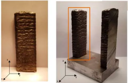
The entirety of the provided components, as well as their dimensions, and identification, are presented in figures 9 to 11 and figures 13 and 14.
It should be noted that powder LMD components have a “Px” identification, with the “P” standing for the powder variant, and “x” being the number identification of the component in no specific order. The wire components on the other hand, have a “Wx” identification, with the “W” standing for the wire variant, and the “x” standing for the number identification, again, in no specific order.
The five powder LMD components are presented below (Figs. 10-12), as well as the deposition strategy used to produce them (Fig. 13).
Figure 10 - Component P1 (left) and P2 (right) originally provided by IK4-Tekniker.
Figure 12 - Component P5 originally provided by IK4-Tekniker.
Figure 13 - Deposition strategy for the base, which is repeated on the z-axis, overlaying layers, creating the final powder components [39].
Table 5 presents the dimensions of the components shown in figures 10 to 12, as well as the deposition height used, which is determined upon the deposition process.
Table 5 - Powder LMD components dimensions (x, y, z).
Number identification x [mm] y [mm] z [mm] Deposition height P1 12.55 28.05 78.80 0.3 P2 13.45 29.00 79.00 0.9 P3 11.10 27.00 77.50 0.8 P4 13.00 26.20 80.00 0.7 P5 13.00 27.50 78.70 0.8
The five wire LMD components are presented below (Fig. 14-16), as well as the deposition strategy used to produce them (Fig. 17), which is similar to the one used on the powder components.
Figure 14 - Component W1 (left) and W2 (right) originally provided by IK4-Tekniker.
Figure 15 - Component W3 (left) and W4 (right) originally provided by IK4-Tekniker.
Figure 17 - Deposition strategy for the base, which is repeated on the z-axis, overlaying layers, creating the final wire components [39].
Table 6 presents the dimensions of the wire components, as well as the deposition height used, which in the case of the wire LMD components, is 0,9mm for all the components given the morphology of the process itself.
Table 6 - Wire LMD components dimensions (x, y, z).
Number identification x [mm] y [mm] z [mm] Deposition height W1 30.60 30.60 99.00 0.9 W2 30.60 30.90 60.00 0.9 W3 30.50 30.90 62.10 0.9 W4 30.30 30.90 37.90 0.9 W5 31.00 30.75 47.35 0.9
3.2. Component preparation
In order to be able to perform further mechanical tests some type of processing had to be done to the components available.
Firstly, the substrate had to be separated from the components themselves, to isolate the deposition base from the deposited material.
Secondly, the parts were processed in a way that an acceptable surface finish was achieved, taking away from the parts the bumps and ridges created by the deposition process.
These bumps and ridges represent one of the biggest limitations of both powder and wire LMD, which leads to a poor surface quality, preventing the direct use of components in an industrial application, and usually requiring further surface treatment to achieve an
Consequently, it is possible to understand that the dimensions that the parts present after processing them into a more acceptable surface quality, are slightly smaller than the ones presented in table 5 and 6, which refer to a rough shape, just as they are produced.
The first preparation procedure step was similar to the powder and wire LMD components, and consisted on the separation of substrate from the deposition material. The selected equipment for this process was a manual cut-off machine, more specifically a Struers Labotom-3 (Fig. 18).
Figure 18 - The equipment Struers Labotom-3 used to separate the deposited material from the substrate.
The result of this process is a separation between the substrate and the deposited material, with a loss of about 1 to 2 mm of material on the z-axis.
In some cases, due to the grooves and ridges present in the surface of the components, as well as the equipment limitations, the cut could not be made exactly in the separation between the two parts, leading to a bigger material loss. However, the surface on which the cut was made presents good surface finish, with minor signs of the cutting disk passage. Figure 19 presents the surface of both the substrate and the deposited material surface after the cut, for a wire and a powder component.
Figure 19 - Representation of a wire (left) and powder (right) component after the separation between the substrate and the deposited material.
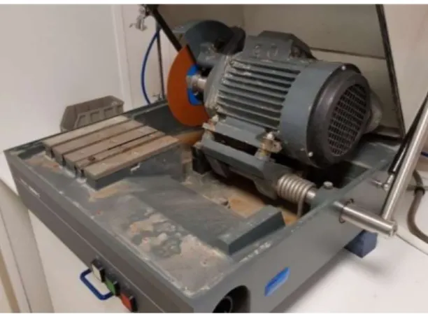
With all of the components separated from their substrate, surfaces with a poor surface finish were grinded or milled, depending on their magnetic behaviour.
On the powder LMD components, given the presence of magnetism, a precision surface grinder was used. The used machine, a Chevalier Falcon FSG-3A818, operates by grinding the surface with increments of 0.02 mm in height, leaving behind a good surface finish. During the process, an effort was made to maintain a continuous lubrification of the components in order to prevent heating effects on material, however some small marks appeared on some of the components. Despite this fact, the areas to be evaluated presented no marks whatsoever.
Regarding the wire LMD components, given the lack of magnetism, a turret milling machine was used, more exactly, a Holke F-10-V machine. This machine also allows the control of the z-axis displacement, allowing increments of 0.1 mm.
The result is a piece with good surface finish, but not as good as the precision surface grinder used on the powder components, since there are visible mill passage marks.
With the test components preparation completed all of the components were in a state that allowed the planning of the experimental tests.
3.3. Methodology
The methodology used to perform the mechanical characterization of the LMD components was built in a way that allowed to maximize the amount of information obtained from each available component, while taking into consideration both the timeframe and the available equipment.
The first mechanical tests to be conducted were the ones that required less component processing, using the components as close to their original state, and the final tests were the ones that required the most component processing.
This also ends up meaning that the first mechanical tests tended to have a non-destructive nature, and subsequently, the last tests tended to have a destructive nature.
Before conducting any of the selected tests the surface had to be prepared given the heavily scratched finish that all of the components showed after the preparation process described in chapter 3.2.
A graphical representation of the timeline of methodology followed for the experimental work is presented in Fig. 20.
Figure 20 - Graphic representation of the conducted mechanical tests, in a timeline.
The first stage was the surface preparation of the test components. This first task was performed before all of the selected mechanical tests were done, in order to assure a good and scratch free surface.
The first mechanical test to be conducted was the microhardness test, a non-destructive test, which was selected given that it offers data that helps to clarify how the components relate to the reference values for the material in which they were manufactured.
The following test was the density test, also non-destructive, requiring however a cut of a small piece on the transversal plan. Density testing was selected given that it clarifies the existence of porosities on some level and allows the comparison of the component’s material with the same material processed through conventional techniques.
The third selected test was an optical microscopy test, also non-destructive, which used the same small pieces obtained for the density test, requiring further polishing in order to obtain a finer scratch-free surface. Optical microscopy testing allows the understanding of the arrangement of the layers, as well as the visualisation of the material microstructure.
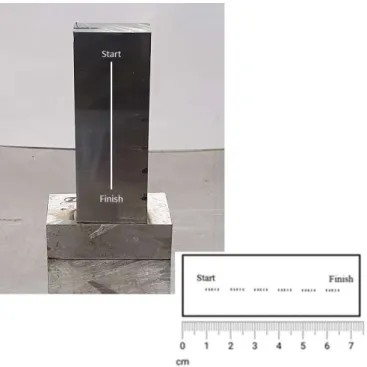
The fourth test was the impulse excitation of vibration test, which is again of a non-destructive nature, but required the cut of a thin rectangular slice (ratio of width to thickness being between 20 and 25) of the component on the vertical axis. This test was one of the last ones to be conducted. This test was selected due to the mechanical properties that it is capable to determine, allowing a good characterization of the components.
Finally, the last test to be conducted was the friction and wear test, the first one of a destructive nature. This test required the cut of small thin pieces that were cut from the slice
Surface preparation Microhardness test Density test Optical microscopy test Impulse excitation of vibration test
Friction and Wear test
used on the impulse excitation of vibration test. This test was selected given that it allows to understand the behaviour of the components under a specific set of conditions, which ends up offering data that can be used to predict how a component produced with this material would behave under real work conditions.
With the methodology schedule defined, each individual stage is now presented in the following chapters.
3.3.1. Surface preparation
In order to eliminate the scratching an incremental process was carried out, where several sandpaper grit sizes were used to eliminate scratches and imperfections, and also to take any hints of oxidation. The sequence of the process is presented in figure 21.
Figure 21 - Surface polishing preparation process.
Some of the used ASTM standards alert to the fact that heating effects during grinding and work-hardening during polishing, should both be avoided. To counteract on this, water was used during grinding, and a specific lubricant was used during polishing to maintain low temperatures.
The machine used to grind, using sandpaper, and polish, using a polishing cloth, the components was the Struers RotoPol-21, which uses 25 mm diameter sandpaper and cloth disks, and rotates with a speed of either 150 or 300 rpm. The machine also allowed the automation of the process, holding specimens in a chamber that is able to rotate and apply a constant normal force of 5 or 10 N, during a previously set amount of time.
The first four stages described in figure 21, consisted on the use of four different sandpaper grit sizes and was conducted on the left plate of the polishing machine visible in figure 22.
The first applied sandpaper presented a coarser surface, and eliminated the bigger scratches and ridges on the surface.
•Grit size - 500
The second sandpaper presented a somewhat coarse surface, since scratches were still visible, and needed to be eliminated. •Grit size - 800
The third applied sandpaper was finer and helped to start the mirroring of the surface.
•Grit size - 1200
The fourth and final sandpaper was very fine, and helped to achieve the wanted mirrored finish.
•Grit size - 2400
The fifth stage, was conducted on a polishing cloth, with pastes containing monocrystaline diamonds with diameter of 6µm and 3µm.
![Table 1 - Comparison between AM and conventional manufacturing techniques, in industry applications [10]](https://thumb-eu.123doks.com/thumbv2/123dok_br/18635574.911406/23.892.276.633.459.727/table-comparison-conventional-manufacturing-techniques-industry-applications.webp)
![Figure 5 - LMD deposition process, with robotic control, application [20] .](https://thumb-eu.123doks.com/thumbv2/123dok_br/18635574.911406/28.892.305.566.101.495/figure-lmd-deposition-process-with-robotic-control-application.webp)
![Figure 6 - Schematic representation of wire drawing [27] .](https://thumb-eu.123doks.com/thumbv2/123dok_br/18635574.911406/30.892.189.655.317.593/figure-schematic-representation-wire-drawing.webp)
![Figure 7 - Schematic representation of the first designed ruby laser [36] .](https://thumb-eu.123doks.com/thumbv2/123dok_br/18635574.911406/33.892.262.653.108.358/figure-schematic-representation-designed-ruby-laser.webp)
![Figure 8 - Components produced by IK4-Teknikerand provided for analysis [37] .](https://thumb-eu.123doks.com/thumbv2/123dok_br/18635574.911406/35.892.217.698.496.849/figure-components-produced-ik-teknikerand-provided-analysis.webp)