THE DEFORMATION OF CYLINDRICAL SHELLS SUBJECTED
TO RADIAL LOADS
Madureira, Luísa R,[email protected]
Departamento de Engenharia Mecânica e Gestão Industrial, Faculdade de Engenharia da Universidade do Porto R. Dr Roberto Frias 4050-465 Porto, Portugal
Fonseca, Elza M. M
Departamento de Engenharia Mecânica, Instituto Politécnico de Bragança, Portugal
Melo, F. J. Queirós
Departamento de Engenharia Mecânica, Universidade de Aveiro, Campus de Santiago, 3810 Aveiro Portugal
Abstract. Cylindrical shells have a simple geometry and application in pressure vessels and piping engineering. The development of calculation algorithms in structural project is impelled by a constant challenge in the search of more accurate and fast design tools in engineering. The objective of this work is to contribute with a simple and reliable numerical tool for the stress analysis of cylindrical vessels subjected to generalized forces. A hybrid formulation in the definition of forces and displacements is proposed for cylindrical shells subjected to radial loads. Variational techniques coupled with functional analysis are used to obtain an optimized solution for the shell displacement and further stress field evaluation. As it is not possible to obtain exact solutions for the displacements or deformation field whenever the external loads are either concentrate or locally distributed, the solution here proposed deals with the combination of unknown analytic functions combined with Fourier expansions, where the former depend on the axial shell coordinate and the trigonometric terms are dependent upon the cylinder circumferential polar angle. These functions are expanded in Fourier series where displacement amplitudes are combined with trigonometric terms. The result is a system of ordinary differential equations where the solution is analytic after evaluation of eigenvalues and eigenvectors. The boundary conditions are then used to reach the final solution. As an example a large cylindrical shell subjected to pinching loads is considered. The results for the radial displacement and section ovalization are analyzed where the solution was obtained with three terms (nθ=6) for the accuracy is acceptable in this case. The transverse displacement presents important dependence on the shell thickness vs radius, as the shell can be a thin-walled one (this case is included in the presented example) up to a moderately thick one, where the surface displacement ranges until the extreme edges, which is not the case analyzed. The proposed method leads to accurate results with a relatively low complexity input data. For conclusions of this work it is remarked that the definitions of the load system and boundary conditions are easily processed as the method has pre-defined possibilities for each load case or edge boundary conditions. An analytic solution is obtained and a low number of terms in the Fourier series show good accuracy. A comparison with finite element methods is presented.
Keywords: piping engineering, Fourier series, system of differential equations, boundary conditions.
1. INTRODUCTION
The displacement field is defined as follows:
∑
=
=
θθ
θ n
i
i
x
i
b
x u
2
)
cos(
)
(
) , (
∑
=
−
=
θθ
θ
ni i
i
x
i
a
x
v
2
)
sin(
)
(
)
,
(
(1)∑
=
=
θθ
θ
ni
i
x
i
a
x
w
2
)
cos(
)
(
)
,
(
where u, v and w are respectively, the axial, the meridional and the transverse shell displacements. The cylindrical shell deformations iclude axial, circumferential and shear membrane terms εxx, εθθ, γxθ, also as
bending curvatures and twist.kxx kθθ and kxθ. These terms together with internal forces Nxx Nxθ, Nθθ
The deformation energy U is a functional U(u, v, w, NxxNxθ, Nθθ) for which the stationarity is obtained
performing a weak formulation with Fourier series amplitude parameter variations. The result is a system of ordinary differential equations where the solution is analytic after evaluation of eigenvalues and eigenvectors. The boundary conditions are then used to reach the final solution.
As an example a large cylindrical shell subjected to pinching loads is considered. The results for the radial displacement and section ovalization are as depicted in the Figures in section 2 where the solution was obtained with six terms (nθ=6) for the accuracy is acceptable in this case. The transverse displacement w presents important dependence on the shell thickness vs radius, as the shell can be a thin-walled one (this case is included in the presented example) up to a moderately thick one, where the surface displacement ranges until the extreme edges, which is not the case analyzed. In the expansions in Eq. (1) the functions ai, bi are the amplitudes for the ovalization and warping displacements. These terms are included in the Fourier θ-expansions, but they are only x-dependent functions.
In this problem the terms used for evaluation of the total energy are, following Millard and Roche (1984):
U=
∫∫
Aε2xx+Sγ2xθ+Dk2xx+Dk2θθ+D −υ k2xθdΩ 2 ) 1 ( 2 1= (2)
[
(
)
( )
( )(
)
( )
]
Ω ′′ + ′ + − − + ∫∫∑ = ′ + − − ′ + − + + = d i i a D i i a r i i D i i a i D r i i i a i b r i S i i b A i θ θ υ θ θ θ 2 cos 2 2 sin 2 2 2 1 2 2 ) 1 ( 2 cos 2 ) 1 2 ( 4 1 2 sin 2 2 cos 7 , 6 , 5 , 4 , 3 , 2 2 1 (3)where dΩ=rdθdx and
(
′′ θ= a i
kxx icos
)
(the shell axial curvature)θ ′ ⎟ ⎠ ⎞ ⎜ ⎝ ⎛− + =
θ a i
i i r
kx isin
1 2 1
(the shell surface twist)
(
)
(
− + θ)
=
θθ i a i
r
k 1 2 1 icos 2
)
(the circumferential curvature) (4)
(
′ θ=
εxx bicosi (the axial membrane strain)
0 =
εθθ (the circumferential membrane strain; is zero as the pipe is
circumferentially inextensible)
θ ⎟ ⎠ ⎞ ⎜ ⎝ ⎛ ′ − − =
γ θ i
i a b r i i i
x sin (the membrane shear strain)
The stationarity condition for U, (corresponding to a minimum, as in fact it is a natural variational principle), is obtained with separate variations of functional U, for each of the unknowns ai, bi (Millard
and Roche, 1984).
0 0 2 2 = ⎟⎟ ⎠ ⎞ ⎜⎜ ⎝ ⎛ ′ δ ′ ∂ ∂ + δ ∂ ∂ = ⎟⎟ ⎠ ⎞ ⎜⎜ ⎝ ⎛ ′ δ ′ ∂ ∂ + δ ∂ ∂ ≥ ≥ i i i i i i i i i i a a U a a U b b U b b U (5)
The solution is now written with totally assumed displacements and its derivatives. Following this procedure, a system of differential equations is obtained. The differential equations for the straight pipe, assuming that the deformation is caused by a force F applied on the surface of the pipe are described in Eq. (6) and solved by evaluation of eigenvalues and eigenvectors (Wylie and Barret, 1995):
(6.1)
F
i
a
r
D
i
i
i
rS
i
b
S
i
a
r
D
i
i
iv
rDa
⎟
⎟
′′
+
⎠
⎞
⎜
⎜
⎝
⎛
π
−
ν
i i
i b Sa
r S i b
rA ⎟⎟ +π ′
⎠ ⎞ ⎜ ⎜ ⎝ ⎛ π = ′′
π 2 (6.2)
2. EXAMPLE
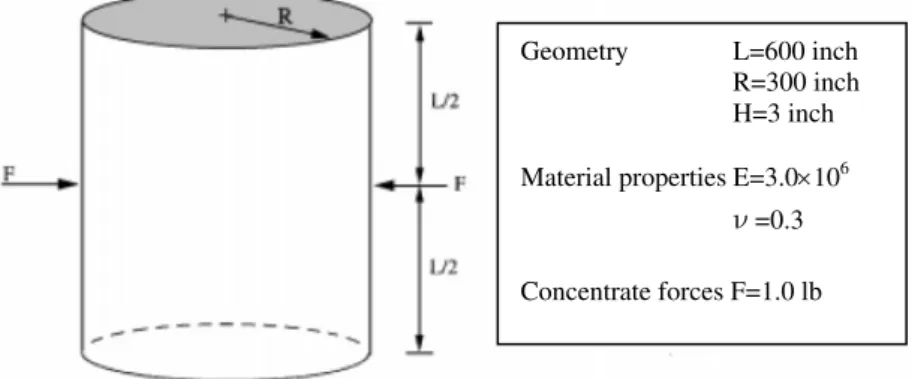
A pinched cylinder with rigid end diaphragms is presented. The cylinder is subjected to diametrical load as shown in Fig 1. This is a benchmark case study frequently analyzed by several authors. The example of a pinched cylinder with the present methodology is compared with the work by Cirak, Ortiz and Schroder (2000) and Fonseca (2007). Simultaneously, numerical simulation using ANSYS finite element program will be presented.
The material properties and the geometric parameters are the following (units are according to the references for comparison):
psi
E
=
3
×
10
6ν
=
0
.
3
r=300 inch L=600 inch h=3 inch
In this example lengths are in inches and load in pounds as published by Fonseca (2007) and Cirak, Ortiz and Schroder (2000). Figure 1 shows the case study including all considered parameters.
Geometry L=600 inch
R=300 inch
H=3 inch
Material properties E=3.0×10⁶
ν =0.3
Concentrate forces F=1.0 lb
Fig.1 - Geometry of a two-radial loads pinched cylinder
2.1 The variational method application
Equation (7) represents the load submitted for this type of analysis and introduced in differential Eq. (6).
F(x) =
600
sin
600
314
cos
600
286
cos
2
59
1
x
n
n
n
n
F
n
π
π
π
π
⎟
⎠
⎞
⎜
⎝
⎛
−
+
∑
=
(7)
Figure 2 shows the load considered on the surface as a Fourier expansion whereF=-0.5pound
Fig.3 – Separate solutions ocorresponding to each ovalization mode
a
2(
x
),
a
3(
x
),...,
a
7(
x
)
Superposing the six solutions gives the optimal solution for the deformation, the vertical displacement along length of cylinder obtained with this hybrid formulation is shown in Fig. 4.
inch
E-05 inch
Fig.4 -
a
2(
x
)
+
a
3(
x
)
+
...
+
a
7(
x
)
for pipe deformationThe next graph shows that these results match the ones obtained with finite element methods by Fonseca (2007), Cirak et al (2000).
-2.0E-05 -1.6E-05 -1.2E-05 -8.0E-06 -4.0E-06 0.0E+00
0 100 200 300 400 500 600
V
er
ti
cal
d
is
p
la
cem
en
t
Length
Ring element (8elem) Ring element (24elem) Shell8 element
Fig.6 –Pipe ovalization at mid length resulting from diametrically opposed pair of forces.
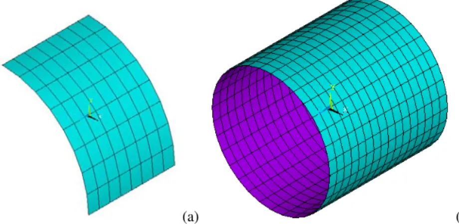
2.2 The finite element method application
The pinched cylinder problem tests the ability of simulation to model complex bending and membrane states. Researchers use the pinched cylinder problem as a benchmark test to assess the performance of curved beam or shells elements as did Fonseca (2007) and Cirak et al (2000). Results of the finite element method using ANSYS program are shown in the next Figures to compare the obtained solution with the functional analysis. In ANSYS program a finite Shell93 element was used, with 8 nodes and 6 degrees of freedom per each node: translations in the nodal x, y, and z directions and rotations about the nodal x, y, and z-axes. Shell93 is particularly well suited to model curved shells. The deformation shapes are quadratic in both in-plane directions. Different analyses are presented. Due to the geometry and load symmetry a one-eighth of the cylinder is modelled and all complete cylinder, being the finite element mesh used in Fig. 7. For the one-eighth symmetry model, one-fourth of the load is applied.
(a) (b)
Fig. 7 – Finite element mesh used for one-eighth (a) and total cylinder length (b).
Figure 8 shows the postprocessor obtained for the vertical displacement results using ANSYS program.
(a) Uymax=-0.182E-04 [in]
(b)
Uymax=-0.180E-04 [in]
Fig. 8 – Vertical displacement for eighth (a) and total cylinder length (b).
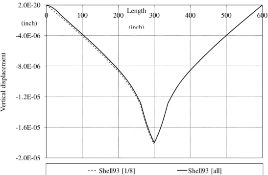
This is known as a benchmark result where there is a dominant bending behaviour in the thin shell limit. The vertical displacement along length of cylinder obtained with two different meshes was compared in the following Fig. 9, similar to the results obtained by Fonseca (2007) in Fig. 5.
-2.0E-05 -1.6E-05 -1.2E-05 -8.0E-06 -4.0E-06 2.0E-20
0 100 200 300 400 500 600
V
erti
cal
d
is
p
la
cem
en
t
Length
Shell93 [1/8] Shell93 [all]
(inch)
(inch)
Fig. 9 – Vertical displacement along the cylinder length (ANSYS solution)
3. CONCLUSIONS
The presented numerical tools have shown a good agreement altogether when analyzing a recurrent problem in piping engineering, the structural behaviour of thin walled cylindrical pipes subjected to radial loads. The variational solution based on functional analysis, though initially demanding some work with closed form analytic methods, has the advantage of leading to a quite simple computational solution by computer implementation. Moreover, the results match consistently with corresponding work run with finite element techniques.and referenced authors. The solution accuracy can be improved by easily expanding the number of trigonometric elements considered in the Fourier expansions included in the presented solution.
4. REFERENCES
Cirak, F; Ortiz, M and Schroder, P, “Subdivision surfaces: a paradigm for thin shell finite element analysis”, Int Journ for Numerical Methods in Engineering, (2000); 47:2039-2072.
Dvorkin, E., Bathe, K.J. (1984). A continuum mechanics based four-node shell element for general non- linear analysis. Engineering Computation, 1, 77-88.
Fonseca, Elza M.M., F.J.M.Q. de Melo and C.A.M. Oliveira, Trigonometric function used to formulate a multi-nodal finite tubular element, Mechanics Research Communications, Volume 34:1 (2007) pp 54-62 Kouhia, R., Stenberg, R. (2000). A simple linear nonconforming shell element. IASS-IACM 2000, Fourth International Colloquium on Computational of Shell Spatial Structures, Greece.
Millard, A., Roche, R. "Elementary Solutions for the Propagation of Ovalization along Straight Pipes and Elbows", Int. Journ. of Press. Vessels & Piping, Volume 16:1 (1984) pp 101-129.
Wylie C and Barret L, Advanced Engineering Mathematics 6th ed, McGraw-Hill (1995).
5. RESPONSIBILITY NOTICE
The authors are the only responsible for the printed material included in this paper.
6. AKNOWLEDGEMENTS