EFFECTIVE LIMITATION OF LINE FAULT CURRENTS BY MEANS OF THE
SERIES-CONNECTED VSC-BASED FACTS DEVICES
R.L. Vasquez-Arnez
∗L.C. Zanetta Jr.
∗F.A. Moreira
†∗Department of Electrical Engineering, University of São Paulo, CEP 05508-900, SP
†Department of Electrical Engineering, Federal University of Bahia, CEP 40210-630, BA
ABSTRACT
In this paper, the nearly instantaneous response of the series-connected VSC-based FACTS controllers when used to limit possible fault currents in a compensated line, will be pre-sented. The effectiveness of both FACTS controllers (SSSC and UPFC) towards this system condition was investigated exploring the series voltage effect upon the line. Moreover, it will be shown that the UPFC shunt converter can also con-tribute to the reduction of such fault currents. The short-circuit current limitation strategy presented herein showed that aside of the power flow control and voltage support com-monly carried out by the SSSC and the UPFC, they could also perform this additional functionality, thus offering a use-ful tool for the protection of the line in which these devices are installed.
KEYWORDS: FACTS, Short-circuit, SSSC, UPFC, VSC.
1
INTRODUCTION
Short-circuit current limiters could be implemented because of two reasons: to reduce the stress within the network and/or to limit the stress over a certain asset, as it might be the
Artigo submetido em 18/08/2005 1a. Revisão em 03/11/2005 2a. Revisão em 27/06/2006 3a. Revisão em 30/10/2006
Aceito sob recomendação do Editor Associado Prof. Carlos A. Castro
case of the series-connected converters referred in this paper. Modern power systems are built with a high degree of flex-ibility so that, ideally, a minimum part of the system would be interrupted during the fault period. Presently, investiga-tions are being carried out to study the coordination of the distance protection and the line’s apparent impedance vari-ation of those lines implemented with FACTS (Flexible AC Transmission Systems) devices, mainly those connected in series with the line. Also, the fault clearing time is not in-stantaneous for it depends on the operating time imposed to the overcurrent relays and the circuit-breaker’s tripping time.
The series-connected VSC (Voltage-Sourced Inverter) based FACTS devices referred in this paper, are: the SSSC (Static Synchronous Series Compensator) and the UPFC (Unified Power Flow Controller). These devices have nearly instan-taneous responses and enable to control more effectively the power flow on the lines where they are installed. As it is known, both the SSSC and the UPFC basically inject a nearly
sinusoidal voltage (Vse)in series with the line. The voltage
(Vq)of the former is in quadrature at an angle ±90˚ with
respect to the line current. The latter also injects a series voltage to the line, but its phase angle can freely rotate along the 360 degrees describing a circle whose maximum radius
is equal toVmax
se .
DC voltage in both devices to fluctuate. This fluctuation is proportional to the line current and to the injected voltage itself. The UPFC shunt VSC helps to cope with this prob-lem by controlling the DC voltage. In other words, the shunt converter damps these fluctuations and keeps the DC voltage almost constant. In this work, it will be considered that the referred fluctuations do not alter significantly the compen-sation characteristic of the devices aimed to limit the fault currents.
In recent years, some other FACTS devices have emerged for developing similar functions. It is the case of the SCCL (Short Circuit Current Limiter) which has shown to be ef-fective for this specific purpose; it is also the case of the TCSC (Thyristor Controlled Series Capacitor) as reported by
Moschakiset alii(2003). The fault limitation approach
pre-sented here may not be cheaper nor simpler than other type of short-circuit current limitation strategies, but it does ex-plore this attractive tool and additional functionality of the series-connected VSC-based FACTS controllers.
In this article, it will be presented the basis to manipulate the series voltage injected from both the SSSC and the UPFC, so as to get the maximum effect whilst limiting short-circuit currents. Further, it will be shown that the UPFC shunt con-verter can also contribute to the reduction of fault currents by forcing the bus voltage at its point of connection, therefore at the fault point, to reduce its magnitude.
2
FAULT CURRENT LIMITATION
It is well established that the short-circuit current levels in a certain network increases proportionally with the addition of lines and new generation. This may jeopardize the transfor-mation and transmission assets in existing power systems, for the short-circuit current rating of such equipment, if not mod-ified and updated or even replaced, will be exceeded. Un-der these circumstances, the fault current limitation offered by modern controllers, characterized by their nearly instan-taneous responses, may become crucial in diminishing such large currents. Hence the interest for analyzing the topic dis-cussed in this paper.
The fault current limitation based on impedance control is a well known subject. For three-phase faults, the inclusion of limiting reactors is a common method whereas for phase-to-ground faults, the use of grounding devices and modi-fications of the zero sequence impedance, are usual prac-tices. However, information on the use and application of the FACTS devices for short-circuit limitation is somewhat scarce. In a study presented by Salem and Sood (2005) a PWM (Pulse Width Modulation) VSC-based SSSC built in the EMTP RV program, is presented. Although in that paper it is also addressed the fault current limitation as an
outstand-1 2 3 4
VSI-1 VSI-2
SW1 SSSC
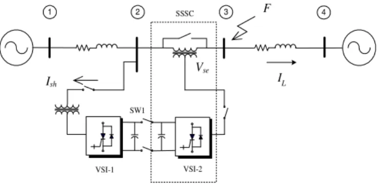
IL F
Vse
Ish
Figure 1: Series-connected VSC-based devices for fault lim-iting analysis
ing byproduct of this device, the authors mainly emphasized aspects such as the inverter’s waveform generation technique and the control system of both the converter itself and the quadrature voltage injected onto the line. The scope of our paper, unlike the one mentioned, emphasizes the effect and contribution of the FACTS devices herein referred for limit-ing fault currents. Still, whenever applicable details of either device implemented in the ATP program, will be included.
The respective leakage reactance of the series coupling trans-former reduces, although to a smaller extent, the short-circuit current that may be originated in the compensated line
(pas-sive fault limitation). Thus, if an emulated reactance of
greater value is inserted into the line, in an almost instan-taneous way, the stress of the compensated line as a result of the fault, can be limited to a considerable degree.
The fault limitation strategy using FACTS devices was
first explored by Duangkamol et alii (2000) followed by
Takeshitaet alii(2002). Here, we will further explore this
topic and will show the contribution of the UPFC shunt and series converters towards this system condition. The system depicted in Figure 1, will be used to analyze and simulate the referred fault current limitation strategy. The simple con-nection of the switch, SW1, makes of the stand-alone oper-ating VSCs (SSSC and STATCOM) to complete the UPFC arrangement. Typically, both SSSC and UPFC devices are
mainly used for power flow control (Gyugyi, 1991; Papicet
alii, 1997; Huanget alii, 2000; Vasquez-Arnezet alii, 2002
and Sen, 1998). An additional function of the shunt VSC being the line voltage support.
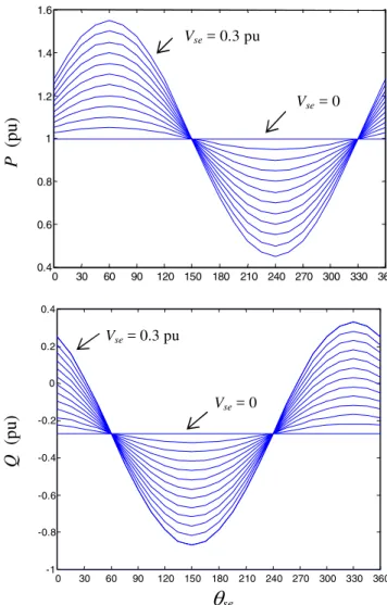
Under no fault conditions, the voltage (Vse)and its respective
angle (θse), will give rise to a family of curves like those
depicted in Figure 2. To obtain these curves both series and shunt converters were regarded as ideal sources operating at
fundamental frequency (Uzunovic et alii, 1998; Yu et alii,
The referred steady-state curves show the extent in which the line’s active and reactive power in the receiving-end, can be controlled. Notice, for the forthcoming analysis, the values
of the series angle (θse)for whichPandQare substantially
compensated.
The condition to achieve the short-circuit current limitation
is to keep the voltageVse(Vq in the SSSC configuration)
in-jected in the line even during the fault period. Recall that for the SSSC case (Sen, 1998), the relation of the
quadra-ture series voltage,Vq, over the line current will be seen by
the system as a compensating reactance, XC, which
emu-lates an inductive (or capacitive) reactance in series with the
lineVq/IL=±jXC. As for the UPFC, the relation between
the series voltage,Vse, and the line current can be seen as a
positive (negative) resistance (±R)and a positive (negative)
reactance (±jX) in series with the line (Gyugyi, 1991).
Al-though this concept can be used to explain the fault current limiting effect, we will prefer to analyze such current control from the series injected voltage viewpoint.
The idea behind the fault-current limitation concept (for three-phase and phase-to-ground faults) is to minimize the voltage at the fault point through the action of the series
volt-age,Vse. This, in fact, is an extension of the Thevenin’s
pre-fault voltage concept at the pre-fault point. For the case of a three-phase fault occurring at bus 3 (Figure 3), it can be seen the contributions of the two independent loops L (left) and R (right) to the fault point. In fact, the series voltage will reduce
the current contribution from the left AC system (E1).
This reduction will be more effective when the UPFC injects positive sequence voltages in opposition to the left equivalent source, which can be estimated in each operative condition. If it is intended to minimize the total current at the fault point, the series voltage injected must be in opposition to the pre-fault voltage at the pre-fault point. As the voltage along the line has a smooth behavior, it is not difficult to set values to cover some other cases of faults along the compensated line.
3
FAULT CURRENT LIMITATION
ANALY-SIS
Initially, it will be defined the left and right equivalent impedances, from the fault point up to each AC source, as
ZLandZR, respectively. For a phase-to-ground fault, which
is the case more likely to occur, the sequence diagrams are sequentially connected, therefore, to minimize the current contributions to the fault, a more careful analysis must be performed. Such an analysis can be done through phase or sequence components.
Thus, regarding the fault point considered in Figure 3, which
can be located at any point along the lineZ2, and with the
0 30 60 90 120 150 180 210 240 270 300 330 360
0.4 0.6 0.8 1 1.2 1.4 1.6
P
(pu
)
Vse= 0.3 pu
Vse= 0
0 30 60 90 120 150 180 210 240 270 300 330 360 -1
-0.8 -0.6 -0.4 -0.2 0 0.2 0.4
θ
seQ
(p
u
)
Vse= 0.3 pu
Vse= 0
Figure 2: Steady-state active and reactive power flow control
(0≤θse≤360˚) at the receiving end
Z2 jXse
Z1
1 2 3 4
1
E E2
se
V
f V
L1
I IL2
f I
Figure 3: Series VSC converter seen as a fundamental fre-quency source for fault analysis
termXseincluded within the equivalent impedanceZL
(left-side), it can be established that:
[E′
Under the absence of the fault, the line current in the system will be,
[IL] = [ZL+ZR]−1[E1′ −E2] (2)
The pre-fault voltage at bus3can be expressed as:
[V3] = [E2] + [ZR][IL] (3)
Substituting (2) into (3) and callingM the matrix that
repre-sents the voltage divider, yields:
[V3] = ([I]−[M]) [E2] + [M][E1] + [M][Vse] (4)
where,[I]represents the identity matrix. Also,
[M] = [ZR][ZL+ZR]−1 (5)
In order to simplify (4), the first two terms (i.e. those affected
byE1,E2without the effect ofVse)will be named asVuf
(uncompensated fault voltage), whereas the last term will be
designated asVsc (series compensating voltage at the fault
pointF). Thus, the compensated fault voltage (Vf)in (4),
formerV3, becomes:
[Vf] = [Vuf] + [M][Vse] (6)
To minimizeVf, the compensation term[M][Vse]has to be
in opposition toVuf, with the series voltage (Vse)being
in-serted at its maximum possible magnitude during the fault period.
The above equations and analysis correspond to a generic case of a tripolar fault. For the case of a phase-to-ground fault, some other aspects, such as the effect of the healthy phases should also be considered. This aspect is to be clari-fied (i.e. to observe whether the coupling effect of the unaf-fected phases can contribute or not to the fault current limi-tation). In the analyzed case only the inductive effect of the unaffected phases, will be considered. So, if the product of the resulting impedance matrices in (5) were renamed as that shown in (7) where to simplify the analysis transposed lines are considered, we will have:
[M] =
α β β
β α β
β β α
(7)
Factorsα,βare dependent on the equivalent impedancesZL
andZRand on the zero and positive sequence values which
define the coupling effect between phases. The substitution of (7) into (6), yields:
¯
Vf a
¯
Vf b
¯
Vf c
=
¯
Vuf a
¯
Vuf b
¯
Vuf c
+
α β β
β α β
β β α
¯
Vsea
¯
Vseb
¯
Vsec
(8)
For instance, the corresponding terms affecting the fault
point at phasea, are:
¯
Vf a= ¯Vuf a+αV¯sea+β
¯
Vseb+ ¯Vsec
(9)
For the case of the system depicted in Figure 3, ifZL1=0.25,
ZL0=0.545,ZR1=0.25,ZR0=0.8695, then, the values of the
factorsαandβ computed, will be: α=0.538 andβ=0.038.
Thus, according to (9) two different strategies can be adopted
for analyzing the effect of the voltageVse.
a) Regarding the positive sequence in the three phases
( ¯Vsea+ ¯Vseb+ ¯Vsec= 0), then, the voltageVseat phase
awill be:
¯
Vf a= ¯Vuf a+ (α−β) ¯Vsea (10)
in this case, the healthy phases can introduce a deleteri-ous effect on the voltage at the fault point.
b) With the introduction of the zero sequence voltage
( ¯Vsea= ¯Vseb= ¯Vsec)equation (9) becomes:
¯
Vf a= ¯Vuf a+ (α+ 2β) ¯Vsea (11)
The voltage control is improved compared to the previ-ous positive sequence voltage compensation.
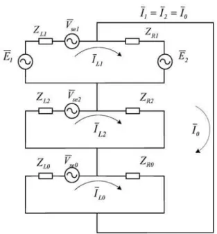
In order to analyze the contribution of the currents to the fault point, it will also be examined the sequence impedance dia-grams depicted in Figure 4, in which:
¯
I1,I¯2,I¯0: sequence components of the fault current.
¯
IL1,I¯L2,I¯L0: sequence components of the left-side
equiva-lent contribution.
Figure 4: Phase-to-ground fault: equivalent sequence dia-grams
¯
E1+ ¯Vse1−E¯2
¯ Vse2
¯ Vse0
¯ E2
=
(ZL1+ZR1) 0
0 (ZL2+ZR2)
0 0
−ZR1 −ZR2
0 −ZR1
0 −ZR2
(ZL0+ZR0) −ZR0
−ZR0 (ZR1+ZR2+ZR0)
¯
IL1 ¯
IL2 ¯
IL0 ¯
I0
(12)
or, in its compact form:
[E] = [Z][I] (13)
VoltagesV¯se1,V¯se2andV¯se0are the sequence components of
the series voltage injected by the UPFC. Recalling also that:
[I] = [Y][E] (14)
Where: [Y] = [Z]−1, then the zero sequence fault current
can be obtained through (15):
¯
I0=Y41E¯1+(Y41−Y44) ¯E2+(Y41V¯se1+Y42V¯se2+Y43V¯se0)
(15)
The first two terms of the second member in (15) represent the fault current without the presence of the series voltages. The remaining terms representing the contribution of the se-ries voltage. Obviously, the fault current can be obtained through:
¯
If = 3 ¯I0 (16)
Equation (14), shown some lines above, is in accordance to the concept of minimizing the pre-fault voltage at the fault point and it shows the most significant effect of applying pos-itive or zero sequence voltage by analyzing the admittance
matrix terms with positionsY41orY43, similarly to the
anal-ysis developed in (10) and (11). Let’s now obtain the left-side equivalent contribution to the fault current.
¯
IL= ( ¯IL1+ ¯IL2+ ¯IL0) (17)
This current is obtained through the addition of the first three rows in (14) in which the equivalent admittances are defined as:
Yj=
3
i=1
Yij (18)
where,Yjis composed by the sum of the first three elements
of each column.
A similar expression to that shown in (14) can be developed
for the left-side current contribution (ILC)to the fault
cur-rent. That is:
¯
ILC=Y1E¯1+ (Y1−Y4) ¯E2
¯
ILU(uncompensated)
+Y1V¯se1+Y2V¯se2+Y3V¯se0
¯
ILSC(contribution ofVse)
(19)
Again, the first two terms of the second member in (19) refers to the fault current contribution without the series voltage
(I¯LU), whereas the remaining terms refer to the series
volt-age contribution (I¯LSC). In order to minimize the
contribu-tion to the total fault current,I¯LSC must be in opposition to
¯
ILU. The best strategy for applying either the positive or zero
sequence voltage fromV¯se, for each specific system, must be
chosen analyzing the elementsY1andY3defined in (18). For
Y1 Y3
Y =−j
0.0615 0.018 0.034
0.018 0.0615
0.034
0.034 0.034 0.0875
0.0361 0.0361 0.0679
0.0361 0.0361 0.0679 0.0722
(20)
For this case, Y1=-j0.1135 pu and Y3=-j0.1554 pu, thus,
the values computed for the currents in (19) result in: ¯
ILU=15.46 -95.56˚pu, I¯LSC=5.25 87˚pu, I¯LC=10.22
-96.87˚ pu. For this particular system, the zero sequence
ap-plication of the series voltage,V¯se0, becomes more effective
to reduce the left equivalent contribution to the fault current. Finally, with the sequence components it can also be
ana-lyzed the total fault current in (16). As|Y43| > |Y41|, the
zero sequence voltageV¯se0is again more effective for the
to-tal fault current reduction, this being in agreement with our previous analysis performed with phase components.
3.1
UPFC MODEL AND
IMPLEMENTA-TION
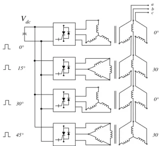
In this section, it will be presented the main aspects related to the UPFC implementation in the ATP program. In order to generate the waveforms in each VSC, it was used the Har-monic Neutralized (HN) technique which consists in the se-ries connection of all the wye connected secondary wind-ings of the transformers within the magnetic circuit. In this way, the equivalent output waveform, containing 12, 24 or 48 pulses, will be composed by the sum of all the individual 2-level or 3-level inverters, depending on the type of config-uration used. So as to generate the desired waveforms, the phase-shift among the inverters implemented must be prop-erly set up. The four VSC-based inverters depicted in Fig-ure 5, upon which was built our model, make use of this
technique using common∆-Y transformers as the magnetic
interface between the VSCs and the AC system. A more detailed description on the waveform generation using this
technique can be found in the reference authored by Senet
alii(1998).
The control sequence followed by the UPFC shunt current
(Ish)and the series voltage (Vse)along with their associate
variables, are shown in Figures 6(a) and 6(b), respectively. The shunt controller adjusts dynamically the phase angle
be-tween the VSC-1 and busV2in order to generate or absorb
MVArs at the connection point. The series VSC operates similarly to the shunt controller, in this case though adjusting
the series angle. The variables with a superscriptref can be
specified and will become the reference values for the con-trollers’ adjustment. The errors between the measured and
Vdc a b c 0° 0° 15° 30° 45° 30° 30° 0°
Figure 5: Generic arrangement for the HN technique
Shunt VSI
sh
Ish (d,q)
Ishqref Vsh
PLL constants
(PI)
P L L ✁
V2
abc ds, qs
Shunt Controller ✂ Firing control Magnetic interface c sh V c sh V (a) Series VSI se ✄ ref se ☎ ILine Ish V2
Vseref
idc, Vdc
V3
Vse
Vse
Vsh
abc ds, qs
✄
Exchanged power Line & VSIse
Receiving-end Power PR, QR
Firing control Magnetic interface Power from VSIsh Power to VSIse DC link idc= (idc1- idc2) Series Controller c sh V Ish(d,q) c se V idc_sh idc_se idc
V2, V3
(b)
Figure 6: Simplified control block diagram of the UPFC
the specified values in each VSC are processed in a PI con-troller that computes the respective output variables.
Table 1: UPFC parameters
Parameter Value
Line nominal voltage Apparent power Switching devices
DC link voltage Coupling transformer X
138 kV
±50MVA
GTOs – 24 pulses 25 kV
8%
implementation of the UPFC, were (table 1):
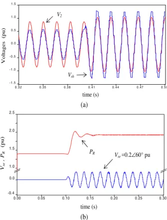
The results corresponding to the steady-state operation of the UPFC, are shown in Fig. 7. Notice the output
wave-form of the shunt inverter (Vsh)depicted in Fig. 7(a) and the
effect of the series voltage (Vse)over the power flow (Fig.
7b). The steady-state operation of the SSSC implemented, also showed satisfactory results. The SSSC implementation and waveform generation in ATP virtually followed the same procedure as its akin UPFC, except for the aforementioned quadrature operation of its series voltage imposed.
4
SIMULATION RESULTS
In this section, it will be shown the simulation results ob-tained in the ATP program. The system depicted in Figure 1, was used to simulate and assess the SSSC and the UPFC effectiveness in limiting the fault currents. For all the simu-lated cases (except Figure 10), the ground switch was set to produce the fault at t=0.1 s. Unless otherwise indicated, the results shown in this section pertain only to the contribution of the left-side AC system, with the measuring switch con-nected between the series coupling transformer and bus 3. The instant at which the series voltage is inserted was arbi-trarily chosen. According to the tests carried out, it can with no restrictions be inserted at the very beginning of the fault.
4.1
SSSC case
Observe in Figure 8, the limiting effect of the series voltage
(Vq=0.3 pu, inductive) when inserted to the line at t=0.20 s.
Should a capacitive mode of compensation of the voltageVse
be injected prior to the fault, the line fault current would
in-crease as the relationVq/IL will be seen by the system as a
capacitive reactance which reduces the equivalent impedance of the line. This deleterious effect of capacitive compensa-tion during faults, should also be taken into consideracompensa-tion.
On the other hand, a study regarding possible harmful ef-fects of the short-circuit current upon the converters is also recommended to be performed, since the sudden increase of the line’s current could be hazardous for the series inverter, specially if maintained for prolonged periods. Recall that the fault withstanding capability of the series VSCs depends
0 .3 2 0 .3 5 0 .3 8 0 .4 1 0 .4 4 0 . 4 7 0 .5 0
- 1 .5 - 1 .0 - 0 .5 0 .0 0 .5 1 .0 1 .5
Vsh V2
Vo
lt
ag
e
s
(p
u
)
time (s)
(a)
1.0 1.5 2.0 2.5
0.00 0.05 0.10 0.15 0.20 0.25 0.30 -0.4
0.0
Vse=0.2∠60° pu PR
Vse
,P
R
(pu)
time (s)
(b)
Figure 7: Equivalent (a) shunt and (b) series waveforms gen-erated by the UPFC (quasi 24-pulse scheme)
0 . 0 0 0 . 0 5 0 . 1 0 0 . 1 5 0 . 2 0 0 . 2 5 0 . 3 0 - 8
- 6 - 4 - 2 0 2 4 6 8
time (s) Short-circuit
IC
(p
u
)
Figure 8: Limitation of the left-side current contribution by means of an SSSC. Tripolar short-circuit (phase C)
mainly on the characteristics of the power semiconductors within the inverters (Moran, 1996).
4.2
UPFC case
If during the fault period the series angle is set to operate
with a value within the rangeθse=120˚→180˚, a large series
0 .0 0 0 .0 5 0 .1 0 0 .1 5 0 .2 0 0 .2 5 0 .3 0 -5 .0
-2 .8 -0 .6 1 .6 3 .8 6 .0
IB
(p
u
)
Short-circuit
time (s)
Figure 9: Limitation of the left-side current contribution by means of a UPFC. Tripolar short-circuit (phase B)
The pre-fault angle of bus 3 is 15 degrees, which means that the referred voltage, thus the total fault current, can be
min-imized through an angleθse=165˚; whereas to minimize the
left equivalent contribution, an angle equal toθse=180˚ in
opposition to the 0˚ (degrees) of the left equivalent voltage, would be needed. The UPFC response towards the tripolar short-circuit current, is shown in Figure 9. The three-phase fault currents shown in Figures 8 and 9 were reduced in ap-proximately 30%.
4.3
Shunt Converter Contribution to the
Fault Current Limitation
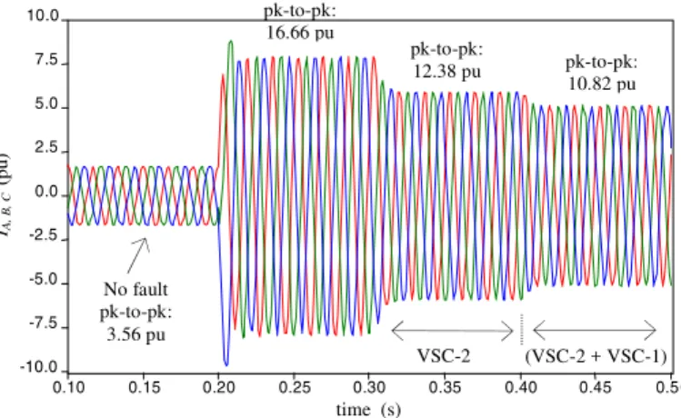
As for the UPFC case, an additional strategy can be used to limit the fault current. Such a strategy consists in utilizing the shunt converter (VSC-1) so as to force the voltage, at the point where this converter is connected (therefore at the fault point), to reduce its magnitude. The total reduction of the short-circuit current in the left-side of the circuit goes from 16.66 pu (fault current amplitude in the time interval
t=0.20→0.30 s) down to approximately 10.82 pu (Figure 10).
This represents a reduction of about 44.58% in relation to the peak-to-peak current value existing during the no fault
condition. The first limiting stage (t=0.30→0.40 s) pertains
to the series voltage action (VSC-2), whereas the second one
(t=0.40→0.50 s) to the effect of the shunt converter (VSC-1).
This reduction strategy does not necessarily have to follow the sequence shown in Figure 10. In fact, both compensators should act simultaneously for a more effective fault current reduction.
The elapsed time with fault (t=0.20→0.30 s.) prior to the
application of the series voltage, has also been chosen arbi-trarily. It by no means indicates that this will be the time needed by the FACTS devices to respond or become effec-tive. Actually, in order to avoid problems with the conven-tional protection system, this strategy should be applied at the onset of the fault. In this way, the current limitation
ef-0.10 0.15 0.20 0.25 0.30 0.35 0.40 0.45 0.50 -10.0
-7.5 -5.0 -2.5 0.0 2.5 5.0 7.5 10.0
time (s)
VSC-2 (VSC-2 + VSC-1)
No fault pk-to-pk:
3.56 pu
IA,
B
,
C
(pu)
pk-to-pk:
12.38 pu pk-to-pk:
10.82 pu pk-to-pk:
16.66 pu
Figure 10: Contribution of the shunt converter (VSC-1) to limit the left-side fault current (three-phase short-circuit)
fectiveness will only depend on the stress that the semicon-ductor switches can withstand. Also, this current limitation strategy may imply both an appropriate rating of the convert-ers and the strengthening of the series coupling transformer’s iron, so as to avoid saturation.
4.4
UPFC Phase-to-Ground Fault
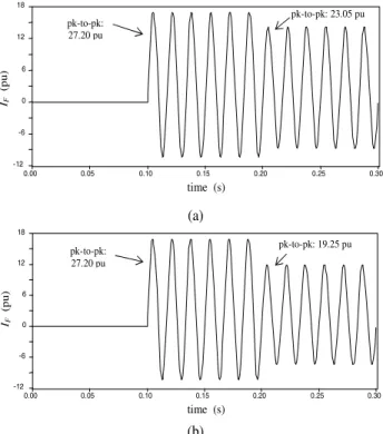
The results corresponding to the phase-to-ground fault anal-ysis developed in Section 2, regarding the equivalent positive and zero sequence impedances of the left and right AC sys-tems, are illustrated in Figure 11.
The total fault currents are reduced from 27.20 pu (uncom-pensated) down to about 23.05 pu and 19.25 pu, when the
positive and the zero sequence voltages (Vse1andVse0)are
applied, respectively. For this specific system, the series
an-gles used wereθsea=165˚,θseb=45˚,θsec=285˚ (for the
posi-tive sequence application) andθsea=θseb=θsec=165˚ (for the
zero sequence application).
4.5
Further Comments
The three-phase faults simulated in the ATP program were applied to a balanced system. Likewise, the converter topol-ogy corresponded to a common neutral-point clamped three-level VSC converter. That is, no special type of converter was built. For practical applications, it would be advantageous to implement 2-level VSC-based converters. Although, as
reported by Schauderet alii (1998) a 3-level inverter
con-figuration (as the one utilized in the AEP Inez Station) could also be feasible and advantageous for real world applications. The use of 3-level inverter configuration is also becoming more common for assessing the FACTS devices’ response in
0.00 0.05 0.10 0.15 0.20 0.25 0.30 -12
-6 0 6 12 18
pk-to-pk: 23.05 pu pk-to-pk:
27.20 pu
IF
(pu)
time (s)
(a)
0.00 0.05 0.10 0.15 0.20 0.25 0.30
-12 -6 0 6 12 18
pk-to-pk: 27.20 pu
pk-to-pk: 19.25 pu
time (s)
IF
(pu)
(b)
Figure 11: Total phase-to-ground fault current reduction: (a)
Positive sequence application ofVse, (b) Zero sequence
ap-plication ofVse
1999).
Of course, for phase-to-ground and bipolar faults the nega-tive and zero sequence components must be incorporated in the ATP program. For both unbalanced systems and faults, it will be essential to have capability to inject different volt-age phasors into all three phases, this research is currently underway.
Both shunt and series inverters have PI (Proportional-Integral) type of controllers that compare the reference (spec-ified) parameters with those existing previously in the sys-tem. Also, the PLL (Phase-Locked Loop) controller used has no particular features. However, the idea while adjusting it was to find some PLL constants robust enough to operate under both normal and fault conditions, rather than building extra control systems aimed only to fault current limitation. For a proper operation of the converter (case of unbalanced systems) the PLL should be able to track adequately each
phase (Songet alii, 1999; Kauraet alii, 1999).
The primary objectives of the FACTS devices regarded herein are the power flow control and the line voltage sup-port. The short-circuit limitation strategy explored, showed that the SSSC and the UPFC may offer a useful additional functionality when implemented within the network.
5
CONCLUSIONS
This paper covered the main aspects of the steady-state AC series voltages when inserted into the power system during fault conditions. It has been observed that, aside of the power flow control characteristic and line voltage support, the series connected VSC-based devices considered (SSSC and UPFC) could be effective tools for limiting fault currents rather than being by-passed during such periods. Both devices may well overcome the continuously increasing short-circuit currents, resulting from the system expansion, which may jeopardize the fault current withstanding capability of existing assets.
The paper presented the basis to manipulate the series volt-age in order to get the maximum effect while limiting short-circuits. Although in the analysis it was focused mainly the three-phase and line-to-ground faults for total and par-tial (branch contribution) fault currents, it could easily be ex-tended to other type of faults. It has been shown that the UPFC shunt converter can also contribute to the reduction of the fault current. This can be achieved by forcing the line voltage to reduce its magnitude, thus, the fault current will do so. The magnitude of the series voltage used along the work was limited to 0.3 pu. The possibility to use higher values during short periods, could be translated in a more efficient compensation effect upon the short-circuit current. This as-pect is still being investigated.
REFERENCES
Duangkamol, K, Y. Mitani, K. Tsuji and M. Hojo (2000). Fault Current Limiting and Power System Stabilization
by Static Synchronous Series Compensator. Proc.
In-ternational Conference on Power System Technology (PowerCon2000), Australia, pp. 1581-1586.
Duangkamol, K., Y. Mitani and K. Tsuji (2001). Power System Stabilizing Control and Current Limiting by a
SMES with a Series Phase Compensator.IEEE
Trans-actions on Applied Superconductivity, Vol. 11, No. 1, pp. 1753-1756.
Dufour C. and J. Bélanger (2005). Real-time Simulation of a 48-Pulse GTO STATCOM Compensated Power System
on a Dual-Xeon PC using RT-LAB.Proc. International
Conference on Power Systems Transients (IPST’05), Montreal, June 19-23, 2005.
Gyugyi, L. (1991). Unified Power Flow Control Concept for
Flexible AC Transmission Systems. IEE Proc. of the
5th International Conference on AC and DC Power
Transmission Conf., London, UK, Issue 345, pp. 19-26.
in Interconnected Power Systems – Modeling,
Inter-face, Control Strategy and Study Case.IEEE
Transac-tions on Power Systems, Vol. 15, No. 2, pp. 817-824.
Kaura, V. and V. Blasko (1997). Operation of a Phase Locked
Loop System Under Distorted Utility Conditions.IEEE
Transactions on Industry Applications, Vol. 33, No. 1, pp. 58-63.
Moran, L., R. Oyarzun, L. Pastorini, J. Dixon and R. Wal-lace (1996). A Fault Protection Scheme for Series
Ac-tive Power Filters.Proc. Power Electronics Specialists
Conference - PESC, Vol. 1, pp. 489-493.
Moschakis, M.N., E.A. Leonidaki and N.D. Hatziargyriou (2003). Considerations for the Application of Thyris-tor Controlled Series CapaciThyris-tors to Radial Power
Dis-tribution Circuits.Proc. IEEE Power Tech Conference,
Bologna, Vol. 3, pp. 1-7.
Ooi, B.T., G. Joos, X. Huang (1999). Operating Principles of Shunt STATCOM Based on 3-Level Diode-Clamped
Converters.IEEE Transactions on Power Delivery, Vol.
14, No. 4, pp. 1504-1510.
Papic, I., I. Zunko, D. Povh and M. Weinhold (1997). Basic
Control of Unified Power Flow Controller.IEEE
Trans-actions on Power Systems, Vol. 12, No. 4, pp. 1734-1739.
Salem S. and V.K. Sood (2005). Modeling of Series Voltage
Source Converter Applications with EMTP RV. Proc.
International Conference on Power Systems Transients (IPST’05), Montreal, June 19-23, 2005.
Schauder C., E. Stacey, M. Lund, L. Gyugyi, L. Kovalsky,
A. Keri, A. Mehraban, A. Edris (1998).AEP UPFC
Project: Installation, Commissioning and Operation of
the ±160 MVA STATCOM (Phase I).IEEE
Transac-tions on Power Delivery, Vol. 13, No. 4, pp. 1530-1535.
Sen, K.K and E.J. Stacey (1998). UPFC-Unified Power Flow
Controller: Theory, Modeling and Applications.IEEE
Transactions on Power Delivery, Vol. 13, No. 4, pp. 1953-1960.
Sen, K.K. (1998). SSSC-Static Synchronous Series
Compen-sator: Theory, Modeling and Applications.IEEE
Trans-actions on Power Delivery, Vol 13, No 1, pp. 241-246.
Song, H.S., H.G. Park and K. Nam (1999). An Instantaneous Phase Angle Detection Algorithm under Unbalanced
Line Voltage Conditions.Proc. Power Electronics
Spe-cialists Conference - PESC, Vol. 1, 27 pp. 533-537.
Takeshita, M. and H. Sugihara (2002). Effect of Fault Current Limiting of UPFC for Power Flow Control
in Loop Transmission. Proc. IEEE/PES Transm. &
Distrib. Conference and Exhibition 2002, Yokohama, Japan, Vol. 2, pp. 2032 –2036.
Uzunovic, E., C. Cañizares and J. Reeve (1998). Fundamen-tal Frequency Model of Unified Power Flow Controller.
Proc. North American Power Symposium NAPS, Cleve-land, Ohio, pp. 294-299.
Vasquez-Arnez, R.L. and L.C. Zanetta J. (2002). Unified Power Flow Controller (UPFC): its Versatility in Han-dling Power Flow and Interaction with the Network.
Proc. IEEE/PES Transm. & Distrib. Conference, Yoko-hama, Japan, Vol. 2, pp. 1338-1343.
Yu, Q, D. Round, E. Norum and T. Undeland (1996). Per-formance of a Unified Power Flow Controller Using a
D-Q Control System.Proc. IEE AC & DC Transmission