An FPGA Implementation of OFDM Transceiver for LTE Applications
Tiago Pereira, Manuel Violas, João Lourenço, Atílio
Gameiro, and Adão Silva
Instituto de Telecomunicações Universidade de Aveiro
Aveiro, Portugal
e-mail: [email protected], [email protected], [email protected], [email protected], [email protected]
Carlos Ribeiro
Instituto de Telecomunicações Escola Superior de Tecnologia e GestãoInstituto Politécnico de Leiria Leiria, Portugal e-mail: [email protected]
Abstract – The paper presents a real-time transceiver using an Orthogonal Frequency-Division Multiplexing (OFDM) signaling scheme. The transceiver is implemented on a Field-Programmable Gate Array (FPGA) through Xilinx System Generator for DSP and includes all the blocks needed for the transmission path of OFDM. The transmitter frame can be reconfigured for different pilot and data schemes. In the receiver, time-domain synchronization is achieved through a joint maximum likelihood (ML) symbol arrival-time and carrier frequency offset (CFO) estimator through the redundant information contained in the cyclic prefix (CP). A least-squares channel estimation retrieves the channel state information and a simple zero-forcing scheme has been implemented for channel equalization. Results show that a rough implementation of the signal path can be implemented by using only Xilinx System Generator for DSP.
Keywords – Software Defined Radio; OFDM; FPGA; time-domain synchronizatio; least square channel estimation.
I. INTRODUCTION
This paper is an extension of work originally reported in [1]. Software-Defined Radio (SDR) is both the popular research direction of the modern communication and the key technology of the 3rd generation mobile communication [2]. Ideally, in a receiver, it is an antenna connected to an Analog-to-Digital Converter (ADC) and a digital signal processing unit. However, Radio Frequency (RF) processing and down conversion is performed on the analog domain
before the ADCs, see Figure 1. SDR is evolving towards the ideal and future SDRs might replace hardware with an intelligent software-controlled RF front-end (FE) [3]. Devised by Joseph Mitola in 1991 [4], it provides control over a range of modulation methods, filtering, frequency bands and bandwidths enabling its adaptability to several wireless standards in order to meet users necessities. Current home radio systems nowadays support at least 4 different radio standards (a/b/g/n) with dedicated circuits for filtering, modulating and processing each standard.
A SDR’s reconfigurability allows the programming of
the required standard instead of building extra hardware according to a standard’s need. If multiple waveforms can be designed to run on a single platform, and that platform can be reconfigured at different times to host different waveforms depending on the operational needs of the user, it stands to reason that fewer platforms may be needed [6]. SDR is forcing a fundamental change in the business model by both platform and waveform developers, in that – although capability is still a key discriminator – the low cost solution wins [6].
Field Programmable Gate Arrays (FPGAs) are mainly used in SDR RF FEs to improve the performance of digital signal processing chip-based systems [7]. Current FPGA vendors include Xilinx, Altera, Actel, Lattice, Tabula, among others. Each vendor has its architectural approach. A FPGA, see Figure 2, is a reconfigurable logical device
Figure 1. The Software-Defined Radio architecture
consisting of an array of small logic blocks and distributed interconnection resources and is characterized by a structure that allows a very high logic capacity. They provide a higher computing power when compared to Digital Signal Processors (DSPs) or General Purpose Processors (GPPs) due to their parallel processing nature, which are essentially serial in operation.
One of the peculiarities of FPGA is “number representation.” Unlike GPPs who are typically equipped with Floating Point Units (FPUs), most DSPs and FPGAs are outfitted with highly parallel multiplier-accumulator cores dedicated to fixed-point precision operations, and even though the support for FPGAs floating-point operations has increased, there are no RF FEs that perform floating-point precisions. In signal processing, the additional range provided by floating point is uncalled for in most cases and fixed-point operations on DSPs and FPGAs provide you a large speed and cost benefit due to their dedicated cores. Still regarding operation speed, if you are running a program on a GPP that has multiple fixed-point multiply/accumulate cores then it will be far faster in fixed-point. On the other hand, on a standard x86 chip, it will actually probably be slower in fixed point. A floating-point representation will have a higher accuracy though and an example is given in [8]. Even though the embedding of FPUs in FPGAs is discouraged; encouragement to improve floating-point support is discussed in [9].
The development of wireless networks is a lasting process that includes many stages, but at some point, verification on a hardware testbed is needed to validate the theoretical and simulation work. Such testbeds are used not only for theory verification, but there are also some concepts that can only be seriously studied in practice (e.g., interference modeling). For instance, rarely a communication theory student needs to spend time understanding the impact of I/Q imbalance, while a student working on a testbed will have to consider such effects.
While theory and simulations typically show the corresponding gains under ideal conditions, hardware platforms and testbeds are essential in validating these gains in real channels and in the presence of implementation impairments [10].
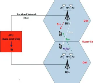
In a distributed antennas system, see Figure 3, the radio signals are jointly processed at a central point, therefore enabling efficient interference mitigation, space diversity and uniform coverage inside the cell. Recently, some practical centralized precoding schemes that can be employed in the considered platform have been proposed [11]-[14]. Two centralized multicell precoding schemes based on the waterfilling technique have been proposed in [11]. It was shown that these techniques achieve a close to optimal weighted sum rate performance. A block diagonalization (BD) cooperative multicell scheme was proposed in [11], where the weighted sum-rate achievable for all the user terminals (UTs) is maximized. A promising centralized precoding scheme based on Zero-Forcing (ZF) criterion with several power allocation approaches, which minimize the average BER and sum of inverse of signal-to-noise ratio (SNR) was proposed in [13][14].
The aim of this article is to present the implementation of an FPGA-based Orthogonal Frequency-Division Multiplexing (OFDM) receiver with a ML time-domain synchronization and a frequency-domain Least-Squares (LS) Channel Estimator (ChEst) using Xilinx System Generator for DSP (SysGen) and Xilinx ISE Design Suite. SysGen is a high-level design “toolbox blockset“ built into Matlab’s Simulink providing the user with high-level abstractions of the system that can be automatically compiled into an FPGA. It provides the user a thin boundary between hardware and software, given that it enables hardware design by allowing the blocks to be synthesized into VHDL and compiling them into a FPGA with a single click. The FE for the platform we are using does require VHDL knowledge, although not all boards in the market do at this point. This allows the user to abstract himself from a time-consuming and knowledge-dependent programming language such as VHDL or Verilog, as well as thousands of lines of code. Even though some SysGen blocks need to be studied for timing and feature purposes, they are in many ways similar to Simulink blocks making them easier to work on.
We discuss some testbeds present on literature nowadays. We present some uncertainties present on the radio domain as well as a possible algorithm to correct them in higher detail along with its implementation. We show our testbed current architecture as well as our go-to deployment scenario. We “focus” on time-domain synchronization using the Beek algorithm and frequency domain LS channel estimation. We show some Bit Error Rate (BER) results with a ZF equalization as well as the simulation method (hardware co-simulation). To finish, we yield some conclusions.
II. BACKGROUND AND RELATED WORK
Although multicarrier techniques can be traced back to 1966 [15], the first commercial application of OFDM occurred only in 1995 with the Digital Audio Broadcasting (DAB) standard [16]. OFDM is a multicarrier bandwidth efficiency scheme for digital communications, where the main difference to conventional Frequency Division Multiplexing (FDM) is that in the frequency domain the OFDM subcarriers overlap, providing spectrum efficiency. Given that OFDM implementations are carried out in the digital domain, there are a number of platforms able to implement an OFDM system suitable for SDR development.
SDR testbeds can be discerned between 2 main fields: hardware platforms and software architectures. The hardware features of an SDR consist of the RF parts and communication links to the software-based signal-processing component. The remaining parts can be composed of a DSP, a FPGA or a GPP.
The BEEcube Company is probably the best growing example on this field and has the Berkeley Emulation Engine 4 (BEE4) as its latest platform. It consists of a platform with 4 different modules, each one supporting a variety of 4 Xilinx Virtex-6, allowing the support of 20 million gate designs per module. Users can run logic up to 500 MHz and digital communication at 640 Gbps per module, along with flexible expansion options such has HDMI. It explores an FPGA capability of processing a large data amount in parallel very quickly. Similar to our system, it also implements its design flow in SysGen. BEE system tests include projects such as an emulation of a Time-Division Multiple Access (TDMA) receiver with an 806 kHz symbol rate using 3 processing FPGAs, 1 crossbar FPGA, and achieves a maximum operating frequency of 25 MHz [17]; a single-channel 2.4 GHz radio system capable of operating in real-time with a 32 MHz system clock rate; a video encoder; a complex iterative decoder design, and other DSP related component designs. Additional BEEcube models include the miniBEE “R&D in a box” platform aimed at smaller designs containing a single Virtex-6 FPGA and targets applications such as Wireless Digital Communications, High Performance Computing, and Video Prototyping, among others. The BEE7 will be introduced in 2013, and will be packaging the latest Xilinx Virtex-7 FPGA family.
Another well-known hardware platform is the Wireless open-Access Research Platform (WARP) from Rice University. One of its fundamental attributes is the central repository [18] dedicated to free distribution of hardware and software projects on the WARP website. It is an extensible reprogrammable platform built for prototyping wireless networks [19]. Their latest model, the WARP v3.0 has a Xilinx Virtex-6 FPGA, two 12-bit ADCs with a sampling rate of 100 MSPS, two 10-bit DACs with a sampling rate of 170 MSPS and comes by default with a 200 MHz Low-Voltage Differential Signaling (LVDS) oscillator. Its capability enables the programmability of both
physical and network layer protocols. For design flow implementation on the WARP hardware platforms, Rice developed two dedicated software architectures, WARPnet and WARPLab. WARPLab is a non-real-time system that brings together WARP and Matlab through an Ethernet switch. One can interact with WARP nodes directly from the Matlab workspace and signals generated in Matlab can be transmitted in real-time over-the-air using the nodes, facilitating rapid prototyping of physical layer (PHY) algorithms directly in Matlab M-Code [20]. Transmitter and receiver processing is performed offline in Matlab. WARPnet is a SDR measurement framework for real-time designs built around client-server architecture in Python [21][22] and it uses a packet capture (PCAP) application-programming interface (API) to communicate with the WARP nodes directly. The PHY layer is implemented on SysGen and VHDL while the Medium Access Control (MAC) layer is implemented in C/C++ code using Xilinx Platform Studio (XPS). Hardware Co-Simulation, see Section 5, is also supported [21][23]. A real-time cooperative OFDM transceiver is presented on [22][23] [24][25]to explore the utility of PHY layer cooperation in real-world wireless systems and early performance results are performed using WARP. An architecture for MAC protocol development and performance evaluation entitled WARPMAC is presented in [22]. A similar work in [26] uses this testbed to present an OFDM-based cooperative system using Alamouti’s block code to study its capability versus a 2 x 1 multiple input single output (MISO) system. It is a suite of software routines that sits above the PHY layer and allows for flexible abstraction of hardware interactions [24][27]. On [25][28] a flexible architecture of a high data rate LTE uplink receiver with multiple antennas is implemented in a single FPGA using SysGen and then verified with WARPLab on a real over-the-air indoor channel supporting data rates up to 220 Mbps.
As for software architectures, the open-source GNU Radio [29] is a development toolkit distributed under the GNU General Public License that provides a set of signal processing libraries for the implementation of the processing blocks required by a transmission system. The GNU Radio project has started in 2001 and now has a large community worldwide devoted to the use of the platform for different applications: OFDM systems, GSM communications, GPS receivers, HDTV receivers, RF sensing, amateur radio applications, FM radio, etc.
The GNU Radio platform runs on Linux-based machines and processing blocks other than the ones given in the libraries are written in C++ language. The flow graph of the system is defined in Python language that defines the interaction among the different blocks.
This platform only implements the digital baseband processing and RF hardware is not part of GNU Radio. To implement the RF transmit and receive paths, off-the-shelf low-cost external hardware is readily available. Some of the boards that interface with the platform are Ettus Research
Figure 4. Transceiver architecture
USRP Series [30], FlexRadio Systems hardware [31], open source HPSDR hardware [32], AMRAD Charleston SDR project board [33], etc. The equipment that stands-out as the most commonly used is the USRP family of devices. A USRP device is made-up of a baseband analog/digital processing motherboard and an RF FE daughterboard. The RF boards cover frequencies from DC to 6GHz with different bandwidths, gains and noise figures. The motherboards are able to process signals with bandwidths up to 50MHz with 100MSamples/s ADCs and 400MSamples/s DACs.
Smaller scale testbeds for OFDM systems based on GNU Radio have been reported in the literature. An OFDM modulator/demodulator with two synchronization options and two error-controlling techniques is reported in [27][34]. The work in [28][35] uses GNU radio to transfer OFDM signals with Quaternary Phase Shift Keying (PSK) and Binary PSK modulation to analyze the packet-received ratio for Quality of Service purposes. An implementation of superposition coding for OFDM systems using the GNU Radio is presented in [34][36]. FPGA implementations of standards 802.11a and 802.16-2004’ modulators using Xilinx System Generator for DSP for high-level design can be found in [37][38].
III. THE ORTHOGONAL FREQUENCY DIVISION MULTIPLEXING TRANSCEIVER
A. Testbed Architecture
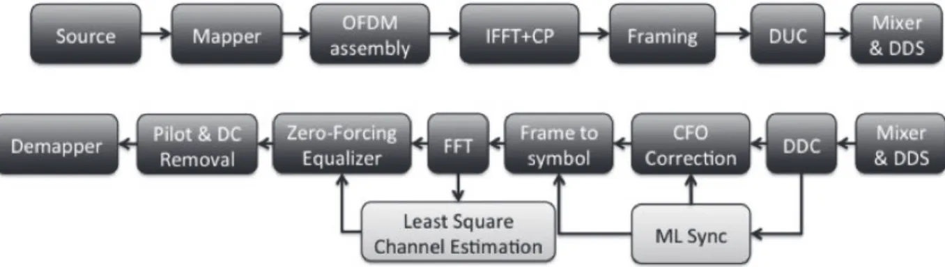
Figure 4 depicts the transceiver architecture of the system discussed in this paper. On the transmitter, data is generated randomly by making an inverse fast Fourier transform (IFFT) of quadrature amplitude modulated (QAM) symbol sets with 1024 subcarriers. The CP is added after the IFFT and the symbols are turned into frames. An up-conversion of 4 is performed on the digital up conversion (DUC) block by a set of two interpolation filters: a square-root-raised-cosine and a halfband.
The mixer and direct digital synthesizer (DDS) block performs frequency translation to an intermediate frequency (IF) and is achieved by mixing the frame with a DDS. On the receiver side, another DDS translates the IF back to baseband on the mixer block. Down-conversion and matched filtering is performed by a similar set of filters as the ones used on the
transmitter by the digital down conversion (DDC) block. Once the estimations for the offsets are performed, the frame to symbol and CFO correction blocks performs the compensations. A fast Fourier transform (FFT) shifts the data back into the frequency domain. A LS channel estimator is implemented to retrieve the channel state information (CSI) and a ZF equalizer applies the estimations. Once pilots and DC subcarriers are removed, the data is demodulated back into bits. Several parameters along the system are reconfigurable at users need. Such parameters include number of symbols per frame, CP length, carrier frequency (limited by the system’s frequency), modulation (QPSK, 16-QAM, 64-16-QAM, etc.) and the system’s main clock frequency, among some others.
Two critical parts of the receiver are the time-domain synchronization and channel estimation subsystems. On the time-domain synchronization, we should estimate the frame arrival time and the frequency offset between the local oscillators and RF carriers. Compensation can then be applied to the received signal. On the channel estimation subsystem on the frequency domain, the CSI will be estimated by a channel estimator and then corrected by an equalizer. In the following subsections, we will detail these two algorithms.
B. Time-domain synchronization - Beek
Receiver and transmitter operate with independent local reference oscillators. In order to perform an efficient demodulation, the receiver should be able to perform frame and carrier synchronization. The first operation defines the starting / ending points of the frame while the latter synchronizes the phase / frequency between transmitter and receiver. Erroneous frame detection is projected into the symbol constellation with a circular rotation, whereas the carrier frequency offset (CFO) causes all the subcarriers to shift and is projected as dispersion in the constellation points. Both ambiguities yield the received signal:
( )
s ( ) j2 k N/( )
r k = k-t e pe + n k (1) where e is the normalized CFO, t is the unknown arrival
number of samples per symbol, n k is the additive white
( )
gaussian noise (AWGN) and k is the sample index of each symbol ranging [0,1023].Moose [39] presented a simple method using the CP just like Beek [40]. Schmidl and Cox [41] use the repetition on the preamble, providing a more robust algorithm for symbol formats where the CP is short.
We do not make use of preamble repetition on our system, although we use Zadoff-Chu (ZC) sequences at the beginning of each frame for time-domain synchronization due to its good autocorrelation properties and given that they are a part of 3GPP Long Term Evolution (LTE) air interface. Beek’s algorithm, see Figure 5, was the chosen one due its mediocre complexity and it can be easily adapted to take advantage of our ZC sequences.
C. Frequency-domain estimation – Least-Squares Channel Estimation
Channel estimation has always been present in wireless communications systems to assist the receiver in mitigating the effects of the wireless multipath channel on the received signal. In OFDM systems, the acquisition of accurate (CSI) is crucial to achieve high spectral efficiency, with emphasis on the demodulation/decoding process, where the frequency response of the channel at the individual subcarrier frequencies needs to be accurately estimated to be used in the decoding process. Furthermore, the synchronization algorithm presents a phase offset ambiguity after frequency offset correction that must be estimated by the channel estimator and removed in the equalization process.
The system discussed in this paper uses the common rectangular pilot pattern adopted by the LTE standard with some adaptations, where a 12 symbol OFDM frame carries pilots in the 1st, 5th and 9th symbol. The pilot-carrying subcarriers are optimally equipowered and equidistant to
Figure 6. Frame structure
achieve the lowest mean square error (MSE) [42][43], considering that the transceiver uses LS channel estimation.
The distance between consecutive pilots is 6 subcarriers. The first and last 208 subcarriers are not loaded making-up the band guards on each end of the spectrum to contain the spectral leakage typical of OFDM systems. An initial ZC training symbol is appended to the frame for synchronization. The frame structure is depicted in Figure 6. This pilot arrangement has been extensively used in the related literature. Some of the outstanding works on channel estimation that used it can be found in [44][45][46].
To overcome the issue of having to extrapolate the edge subcarriers [47][48], with the subsequent degradation of the
ZC symbol Data Pilots Figure 5. Beek estimation algorithm architecture
Empty carriers
estimation accuracy, the adopted frame structure has pilots at both edge subcarriers.
In this work, the initial estimate in the pilot subcarriers used the well-known LS estimator [49]. This classical estimator does not take advantage of the correlation of the channel across the subcarriers in frequency and time domains nor does it use a-priori information on the channel statistics to obtain the estimate, but, on the other hand, presents a reduced implementation complexity, requiring only an inversion and a multiplication per pilot subcarrier. Considering that the value received in the kth pilot subcarrier p k can be expressed by
( )
( )
( ) ( )
( )
u k =s k h k +n k (2)
where h k is the channel value affecting the kth pilot
( )
subcarrier. The LS estimation’s output can be expressed as
( )
( )
( )
( )
( )
( )
ˆ p k n k h k h k s k s k = = + (3)that can be interpreted as noisy samples of the wanted channel frequency response (CFR).
In the literature, some channel estimation schemes output the full channel estimate (for both data and pilot subcarriers) [44], but our initial estimation only outputs the channel values for the pilot subcarriers. It is now necessary to estimate the channel values for the data-carrying subcarriers. The simplest method would be to extend the current channel estimates to the closest pilots in both frequency and time domains [50]. This method only yields acceptable performance if the correlation of the CFR for neighboring pilots is significant. Therefore, it is only adequate for scenarios where the channel varies slowly and has a limited delay spread. The transceiver introduced in
this paper adopted a linear interpolation method in the frequency domain, similar to the one found in [51][52], using a first order polynomial to define the line that connects two neighboring pilots, enhancing the performance of the previous scheme [53]. Higher order polynomials could be used [54]-[56] to achieve higher accuracy in estimating highly selective channels, at the cost of a higher implementation complexity. With the full CFR for the pilot-carrying symbols, and as the pilot separation is small in time domain (4 symbols), the transceiver extends each CFR estimate until next pilot-carrying symbol, to get the full frame CFR.
IV. BEEK ESTIMATION,FRAME SYNCHRONIZATION AND
CFO COMPENSATION
The following subsections present the time-domain synchronization algorithm divided in three parts.
A. Estimation of frame arrival time and carrier frequency offset
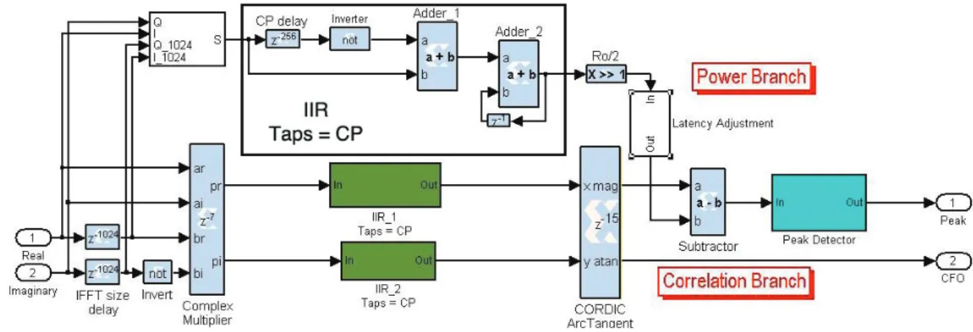
The algorithm presented on this subsection is based on the algorithms developed by Beek and the subsystem created for its purpose and adapted to the frame pattern on Figure 6 is illustrated in Figure 7. Beek exploits the CP by correlating it with a delayed version of itself. When the repeated pattern is located, a peak is generated in order to detect the frame arrival and the phase between patterns gives the CFO.
The algorithm consists of two main branches. The top one calculates an energy term. While the bottom one calculates the correlation term required for estimating both symbol arrival time and phase offset. Equation (4) shows the calculation of the energy term and equation (5) shows the calculation of the correlation term.
( )
(
)
1 2 2 ρ ms1 2 m L k m r k r k N + + = ºå
+ + (4)( ) (
)
1 * ρ ms2 2 m L k m r k r k N + + = ºå
+ (5)The factor ρ is the magnitude of the correlation coefficient between r k and
( )
r k(
+N)
; it depends on the signal-to-noise ratio but can be set to 1. Both moving sums were designed using infinite impulse response (IIR) filters.The complex multiplier core present on the SysGen libraries performs multiplications throughout the subsystem. In order to proceed with both estimations, two operations must be performed on the bottom branch, a complex module to create the peak when the CP correlates with its delayed version and an arctangent to calculate the angle between both IQ signals to enable CFO estimation, see Figure 9. SysGen provides a CORDIC arctangent reference block that implements a rectangular-to-polar coordinate conversion using a CORDIC algorithm in circular vectoring mode, that given a complex-input <I,Q>, it computes a magnitude and an angle according to (6) and (7), respectively.
2 2 Q I Q I, = + (6)
ang=2πe=arctan Q/I
(
)
(7) It is assumed that the offset between oscillators is lower than a single subcarrier and so | | 1/ 2e < . On [57], a division is performed to create the necessary peak for frame arrival detection, but such operation in hardware is more expensive and should be avoided. The only difference brought by the difference operation is how the peak is generated, since the argument to be detected will be close to 0 with a subtraction and to 1 with a division. Achieving a theoretical value of 0 when a signal is detected is not a realistic approach since the fixed-point logic used is subject to quantization errors and to contention of bit propagation along the system. The computed angle is only used when the peak is detected, ensuring the CFO is only used if the correlation is complete.
B. Data forwarding control
This subsystem uses the peak detected for each ZC to process the frame in order for each symbol to be processed by the FFT. Unlike a non-deterministic simulation such as the ones ran in Simulink, a FPGA simulation does not have the ability to hold the information on its own while the estimations described on the previous subsection are executed. Data must be contained in a memory and forwarded when a condition is met or delayed by a constant
value if the process is continuous, which is the case. The processing time required for a peak to be detected and the accurate CFO to be estimated is known, constant and
introduced as a delay before the FIFOs. The peak detected on subsection A triggers the frame writing into the FIFOs. The
CP is not needed anymore so it is not stored. The FFT will require 3*N samples to process each symbol and output it.
This amount of samples needs to be created given that the symbols stored on the FIFOs are continuous. Reading the data stored on the FIFOs at a sampling rate four times higher as the symbols arrive creates that gap, breaking the frame back into separate symbols.
C. Carrier frequency offset correction
Correction of the CFO is achieved with a CORDIC implementing a rotate function [58]. The core rotates the vector (I,Q) by an angle f yielding a new vector (I’,Q’) such that
( )
( )
( )
( )
( )
( )
' cos sin ' cos sin I k I k Q k Q k Q k I k f f f f = ´ - ´ = ´ + ´ (8) where 2 k N/ f= pe (9)Taking the angle achieved at subsection A, the angle is first divided by N and then accumulated along each symbol nullifying the phase offset along each symbol, see Figure 8.
Figure 8. OFDM symbol constellation with a 6 kHz offset between oscillators. Before compensation (left) and after compensation (right)
a .u . a .u . r a d ia n s
Figure 9. Estimation algorithm results for the 1st three symbols of a frame (Zadoff-Chu and two symbols) without AWGN: (a) signal, (b) peak
estimation and (c) computed angle
TABLE I. SYSTEM PARAMETERS
System Parameters
Baseband frequency || Bandwidth 15.36 MHz || 10 MHz
FFT size || CP size 1024 || 256
Modulation QPSK - 16QAM
Subcarrier separation 15 kHz
Symbol duration (Symbol+CP) 66.66 + 16.66 = 83.32 μs
IF sampling frequency 61.44 MHz
Oscillator frequency 15 MHz
D. Estimation Issues
On Figure 8, the received constellation is rotated due to two possible factors, an erroneous frame detection arrival time, which will be discussed shortly, and/or an offset between the oscillators starting time. Both errors are compensated on the channel equalization subsystem on the frequency-domain.
An issue brought by this algorithm is how noise affects the correlation algorithms as seen on Figure 10. Assuming a peak detection algorithm where the peak, that sets the frame start time, is defined on sample N when N+1>N after a given threshold, flawed detections may occur when noise is present. If the peak is detected before the actual peak occurs, a rotation is induced on the constellation and compensated by the channel equalizer. On the other hand, if the peak is detected after the actual peak occurs, random distortion is introduced due to intersymbol interference (ISI) and intercarrier interference (ICI). A peak detection algorithm based on maximum value would always perform a detection closer to the peak, but it would be more time-consuming and it would not be error-free either if the noise disturbed the correlation near the peak. The current algorithm will not avoid this problem either, so we shift the detected peak by three samples into the cyclic prefix to
ensure that the frame start is not set inside the symbols useful time.
V. TESTBED,SIMULATIONS AND RESULTS
Even though we are targeting the 3GPP LTE standard at this point, such implementation can be easily adapted to several other OFDM standards such as 802.11a, WiMAX, among others, given the reconfigurability of the parameters.
The design was compiled through hardware co-simulation. It is a methodology introduced by Xilinx on 2003 [59], which allows a system simulation to be run completely in hardware (FPGA), while showing the results in Simulink. This enables accurate hardware modeling along with faster simulation times due to the faster calculations and easier hardware verification by implementing the manufactured algorithm into the FPGA. Xilinx’s block components behaviors are projected to Simulink, while at the same time; the behavior of each block’s associated hardware component is performed on the FPGA. The objective is to get both hardware and software working before the prototyping stage by providing a better understanding of its behavior.
The targeted model for the simulation was the Xilinx ML605 development board, which contains a Virtex-6 LX240T FPGA, and a 4DSP FMC150 FMC daughter card with a dual 14-bit 250 MSPS ADC and a dual 16-bit 800 MSPS DAC, see Figure 11.
The tests were performed in a wired-channel and the system was run at a system clock of 61.44 MHz with an IF of 15 MHz. The BER hardware results were obtained using Simulink on a hardware co-simulation mode without the daughter card, with some parameters being shown on Table I. The theoretical results were obtained from an adapted Matlab OFDM chain that is used in [60]. Figure 8 was
Figure 11. FPGA hardware platform setup
Figure 12. Baseband BER results for 3 simulations: Perfect CSI (black) and Zero-Forcing Equalization with/without time-domain synchronization (blue
TABLE II. RESOURCE USAGE OF THE FULL SYSTEM
Full system resource usage for Virtex-6
Parameter Used % Slices 7693 19 Slice registers 29395 10 Slice LUTs 25684 17 Block RAMs 42 3 DSP48E 149 19
obtained using Xilinx ChipScope Pro Tool with the daughter card attached. Because of the daughter card present on the testbed, a wrapper must be created with Xilinx ISE Design Suite in order to connect both the system presented here and the daughter card where the DACs/ADCs are present. Table II shows the resources used for the full transceiver, without the wrapper.
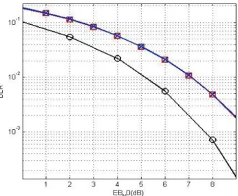
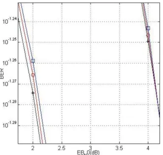
Figures 12 and 13 illustrate the BER theoretical and practical results for three different simulations: perfect CSI, no time-domain synchronization with a ZF equalizer and time-domain synchronization with a ZF equalizer.
VI. CONCLUSION AND FUTURE WORK
A full baseband + IF design was presented focused on the synchronization and channel estimation algorithms. The work presented was performed using Xilinx System Generator for DSP, the ChipScope Pro tool, ISE Design Suite, and validated with Matlab Simulink.
SysGen does not allow the user to replace hardware description language (HDL) completely but allows him to focus the attention on the critical parts of and optimizing paths, HDL is better suited. The amount of resources used for the design was never a priority and can certainly be reduced by optimizing the register transfer level (RTL) of the design to ensure maximum reuse and an efficient implementation [7].
In Figure 9, a rough estimation of the frame is presented, with a peak being generated at the beginning of each symbol and the respective CFO on the bottom, thus proving an accurate arrival time and CFO estimation of each symbol. It is also possible to perform a symbol-based estimation instead
of a frame-based one, with no additional complexity brought by the change.
Figure 8 shows OFDM’s sensitivity to frequency offsets, and even though the CORDIC Rotate corrects the phase along the symbol, the algorithm lacks the ability to compensate for an ambiguous phase offset present on the constellation, later corrected on the channel estimation.
The BER results for a QPSK modulated signal show that the obtained results are according to theory. No relevant differences can be perceived between a baseband and baseband with IF implementation. Our results show a degradation ranging from 1.8 (SNR=10-3.2) to 2.3 (SNR = 0) when the Zero-Forcing equalizer is used which is a feasible result when compared to theory [60]. The time-domain algorithm is also validated; there are no relevant differences between a perfect synchronization simulation and a simulation with Beek’s algorithm.
It is possible to do FPGA simulations with a floating-point representation, but not all blocks present on the SysGen libraries allow such precision and operations on floating point have a higher resource usage in hardware. Also, the FE only allows a fixed-point precision. One discrepancy between such precisions can be seen on Figure 9; when the correlation is occurring the angle should be expressed has a constant flat line. However, due to the lower precision brought by fixed-point, there are some inconsistencies on the line. Unlike the system found in [7], our BER results show no relevant degradation between the Matlab floating-point and FPGA fixed-point simulations, however, we are not limiting the registers bit width along the algorithm and the system parameters are different.
The next step is to direct the work presented here towards a 3GPP LTE MIMO-PHY 2x2 layer implementation along with channel encoding and decoding algorithms.
ACKNOWLEDGMENT
The Portuguese projects CROWN, PTDC/EEA-TEL/115828/2009, and CelCop Pest-OE/EEI/LA0008/2011 as well as the Mobile Network Research Group (MOBNET) from the Instituto de Telecomunicações in Aveiro supported the work presented in this paper.
REFERENCES
[1] T. Pereira, M. Violas. A. Gameiro, C. Ribeiro, and J. Lourenço, “Real time FPGA based testbed for OFDM development with ML synchronization”, in The Seventh Figure 13. BER results for 2 simulations: Perfect CSI (left lines) and
Zero-Forcing Equalization without time-domain synchronization (right lines). Theoretical (black*), baseband (red¢) and IF (blue܆)
International Conference on Systems an Network Communications (ICSNC 2012), pp. 197-200, Lisbon, Portugal, November 18-23, 2012.
[2] Bo Li, “Analysis and design of Software Defined Radio”, in Proceedings of the 2011 International Conference on Internet Computing and Information Services (ICICIS), pp. 415-418, September 2011, doi:10.1109/ICICIS.2011.108.
[3] W. Tuttlebee, “Software Defined Radio: enabling technologies”, John Wiley & Sons, 2002.
[4] J. Mitola, “Software radios survey, critical evaluation and future directions”, in Telesystems Conference, NTC. National, pp. 13/15 –13/23, IEEE, 1992.
[5] T. Pereira, “Tx/Rx baseband implementation of 802.11-2007 on a FPGA”, Masters Thesis, Universidade de Aveiro, 2010. [6] Alan C. Tribble, ”The Software Defined Radio: fact and
fiction”, in Proceedings of IEEE Radio and Wireless Symposium, pp. 5-8, January 2008, doi:
[7] A. A. Tabassam, F. A. Ali, S. Kalsait, and M. U. Suleman, “Building Software-Defined Radios in MATLAB Simulink – A step towards cognitive radios” in Proceedings of the 2011 UKSim 13th International Conference on Modelling and
Simulation, pp. 492-497, 2011 ,doi:
10.1109/UKSIM.2011.100.
[8] W. Zhu, et al., “A real time MIMO OFDM testbed for cognitive radio & networking research”, in Proceedings of the 1st International Workshop on Wireless Network Testbeds, experimental evaluation & characterization
(WiNTECH), pp. 115-116, September 2006, doi:
10.1145/1160987.1161018.
[9] F. de Dinechin, J. Detrey, O. Cret, and R. Tudoran, “When FPGAs are better at floating-point that microprocessors”, in Proceedings of the 16th International ACM/SIGDA symposium on Field programmable gate arrays, pp. 24-26, February 2008, doi: 10.1145/1344671.1344717.
[10] W. Zhu, et al., “Multi-antenna testbeds for research and
education in wireless communications”, IEEE
Communications Magazine, pp. 72-81, vol. 42 issue 12, December 2004, doi: 10.1109/MCOM.20041367558. [11] A. G. Armada, M. S. Fernández, and R. Corvaja,
“Waterfilling schemes for zero-forcing coordinated base station transmission”, in Proceedings of the 28th IEEE
Conference on Global Telecommunications
(GLOBECOM’09), pp. 213-217, 2009, doi:
10.1109/GLOCOM.2009.5425267.
[12] R. Holakouei, A. Silva, A. Gameiro, “Multiuser precoding techniques for a distributed broadband wireless system”, Tellecommunication Systems Journal, Special Issue on Mobile Computing and Networking Technologies, Springer, online version published on June 2011, doi: 10.1007/s11235-011-9496-2.
[13] R. Holakouei, A. Silva, A. Gameiro, “Coordinated precoding techniques for multicell MISO-OFDM networks”, Wireless Personal Communication (WPC) Journal, Springer, 2013, in press.
[14] R. Zhang, “Cooperative multi-cell block diagonalization with per-base-station power constraints”, in IEEE Journal on Selected Areas in Telecommunications – Special Issue on cooperative communications in MIMI celular networks, pp. 1435-1445, vol. 28 issue 9, December 2010, doi: 10.1109/JSAC.2010.101205.
[15] R. W. Chang, “Synthesis of band-limited orthogonal signals for multi-channel data transmission”, Bell System Technical Journal 45, 1966, pp. 1775-1796.
[16] ETS 300 401, “Radio broadcasting systems; Digital Audio Broadcasting (DAB) to mobile, portable and fixed receivers”, ETSI, Feb. 1995.
[17] K. Kuusilinna, C. Chang, M. J. Ammer, B. C. Richards, R. W. Brodersen, “Designing BEE: a hardware emulation engine for signal processing in low-power wireless applications”, in EURASIP Journal on Applied Signal Processing, pp.
502-513, Vol. 2003, January 2003, doi:
10.115/S1110865703212154.
[18] WARP repository, http://warp.rice.edu/trac/browser/ 13.03.2013.
[19] C. Clark, “Software Defined Radio: with GNU Radio and USRP”, McGraw-Hill Professional, November 2008. [20] WARPLab Framework Overview,
http://warp.rice.edu/trac/wiki/WARPLab/ 13.03.2013. [21] WARPnet Measurement Framework,
http://warp.rice.edu/trac/wiki/WARPnet/ 13.03.2013. [22] C. Hunter, J. Camp, P. Murphy, A. Sabharwal, and C. Dick,
“A flexible framework for wireless medium access protocols”, Invited Paper in Proceedings of IEEE Signals, Systems and Computers Conference, ASILOMAR, November 2006.
[23] K. Amiri, Y. Sun, P. Murphy, C. Hunter, J. R. Cavallaro, and A. Sabharwal, “WARP, a unified wireless network testbed for education and research”, in Proceedings of the 2007 IEEE International Conference on Microelectronic Systems Education, pp. 53-54, June 2007, doi: 10.1109/MSE.2007.91. [24] P. Murphy, C. Hunter, and A. Sabharwal, “Design of a
cooperative OFDM transceiver”, in Proceedings of the 43rd ASILOMAR Conference on Signals, Systems and Computers, pp. 1263-1267, November 2009.
[25] P. Murphy, and A. Sabharwal, “Design, implementation and characterization of a cooperative communications system”, in IEEE Transactions on Vehicular Technology, vol. 60, July 2011, doi: 10.1109/TVT.2011.2158461.
[26] P. Murphy, A. Sabharwal, and B. Aazhang, “On building a cooperative communication system: testbed implementation and first results”, EURASIP Journal on Wireless
Communications and Networking, June 2009,
doi:10.1155/2009/972739.
[27] WARPMAC, http://warp.rice.edu/trac/wiki/WARPMAC/
[28] G. Wang, B. Yin, K. Amiri, Y. sun, M. Wu, and J.R. Cavallaro, “FPGA prototyping of a high data rate LTE uplink baseband receiver”, in Proceedings of the 43rd ASILOMAR Conference on Signals, Systems and Computers, pp. 248-252, November 2009.
[29] GNU Radio, http://gnuradio.org/, 2013.
[30] USRP - Universal Software Radio Peripheral, http://www.ettus.com, 13.03.2013.
[31] FlexRadio Systems, http://www.flex-radio.com/, 2013. [32] HPSDR - High Performance Software Defined Radio,
http://openhpsdr.org/index.php, 13.03.2013.
[33] AMRAD Charleston SDR project, http://www.amrad.org/projects/charleston_sdr, 13.03.2013. [34] M. Majó, “Design and implementation of an OFDM-based
communication system for the GNU radio platform”, Master Thesis, Dec. 2009.
[35] A. Marwanto, M. A. Sarijari, N. Fisal, S. K. S. Yusof and R. A. Rashid, “Experimental study of OFDM implementation utilizing GNU Radio and USRP – SDR”, Proc. of the IEEE 9th Malaysia International Conference on Communicatons, Dec. 2009, pp. 132-135.
[36] R. K. Ganti, et al., "Implementation and experimental results of OFDM-based superposition coding on software radio", IEEE International Conference on Communications (ICC'10), pp. 1-5, May 2010, doi: 10.1109/ICC.2010.5502330.
[37] J. Garcia and R. Cumplido, “On the design of an FPGA-based OFDM modulator for IEEE 802.11a”, 2nd International
Conference on Electrical and Electronics Engineering”, Sept. 2005, pp. 114-117.
[38] E J. Garcia and R. Cumplido, “On the design of an FPGA- based OFDM modulator for IEEE 802.16-2004”, 2005 International Conference on Reconfigurable Computing and FPGAs, 2005, pp. 22-25.
[39] P. Moose, “A technique for Orthogonal Frequency Division Multiplexing frequency offset correction”, IEEE Transactions on Communications, vol. 42 no. 10, pp. 2908-2914, October 1984.
[40] Jan-Jaap van de Beek, M. Sandell, and P. O. Börjesson, “ML estimation of time and frequency offset in OFDM systems”, IEEE Transactions on Signal Processing, vol. 45, no. 7, July 1997.
[41] T.M. Schmidl and Cox, and D. C. Cox, “Robust frequency and timing synchronization for OFDM”, IEEE Transactions on Communications, vol. 45, pp. 1613-1621, December 1997. [42] R. Negi, and J. Cioffi, “Pilot tone selection for channel estimation in a mobile OFDM system”, Journal IEEE Transactions on Consumer Electronics, pp. 1122-1128, vol. 44 issue 3, August 1998, doi: 10.1109/30.713244.
[43] I. Barhumi, G. Leus, M. Moonen, “Optimal Training Design For Mimo–Ofdm Systems in Mobile Wireless Channels”, IEEE Transactions on Signal Processing, vol. 51 no. 6, pp. 1615–1624, June 2003.
[44] P. Hoeher, S. Kaiser, P. Robertson, ”Two-dimensional pilot-symbol-aided channel estimation by Wiener filtering,” in Proceedings of IEEE International Conference on Acoustics, Speech, and Signal Processing, pp. 1845-1848, April 1997. [45] S. Kaiser, P. Hoeher, “Performance of multi-carrier CDMA
systems with channel estimation in two dimensions,” in Proc. IEEE Personal, Indoor and Mobile Radio Communications Symposium, pp. 115-119, Helsinki, Finland, September 1997. [46] Y. Li, “Pilot-symbol-aided channel estimation for OFDM in wireless systems,” IEEE Transactions on Vehicular Technology, Vol. 49, Issue 4, pp.1207-1215, July 2000. [47] S. Boumard, A. Mammela, “Channel Estimation Versus
Equalization in an OFDM WLAN System,” in Proc. IEEE Vehicular Technology Conference, vol. 1, pp. 653–657, Rhodes, Greece, May 2001.
[48] M. Shin, H. Lee, C. Lee, “Enhanced Channel Estimation Technique for MIMO–OFDM Systems,” IEEE Transactions on Vehicular Technology, vol. 53, no. 1, pp. 261–265, Jan. 2004.
[49] A. Chini, “Multicarrier modulation in frequency selective fading channels,” Ph.D. dissertation, Carleton University, Canada, 1994.
[50] J. Rinne, M. Renfors, “Pilot spacing in Orthogonal Frequency Division Multiplexing systems on practical channels,” IEEE Transactions on Consumer Electronics, vol. 42 no. 3, pp. 959 – 962, November 1996.
[51] S. Coleri, M. Ergen, A. Puri, A. Bahai, “Channel Estimation Techniques Based on Pilot Arrangement in OFDM Systems,” IEEE Transactions on Broadcasting, vol. 48, no. 3, pp. 223– 229, Sept. 2002.
[52] C. Athaudage, A. Jayalath, “Low–Complexity Channel Estimation for Wireless OFDM Systems,” in Proc. IEEE International Symposium on Personal, Indoor and Mobile Radio Communications, vol. 1, pp. 521 – 525, Beijing, China, Sept. 2003.
[53] S. Coleri, M. Ergen, A. Puri, A. Bahai, “A Study of Channel Estimation in OFDM Systems,” in Proc. IEEE Vehicular Technology Conference, vol. 2, pp. 894 – 898, Vancouver, Canada, Sept. 2002.
[54] X. Wang, K. Liu, “OFDM Channel Estimation Based on Time-Frequency Polynomial Model of Fading Multipath Channel,” in Proc. IEEE Vehicular Technology Conference, vol. 1, pp. 460 – 464, Atlantic City, USA, Oct. 2001. [55] A. Dowler, A. Doufexi, A. Nix, “Performance Evaluation of
Channel Estimation Techniques for a Mobile Fourth Generation Wide Area OFDM System,” in Proc. IEEE Vehicular Technology Conference, vol. 4, pp. 2036 – 2040, Vancouver, Canada, Sept. 2002.
[56] S. Lee, D. Lee, H. Choi, “Performance Comparison of Space-Time Codes and Channel Estimation in OFDM Systems with Transmit Diversity for Wireless LANs,” in Proc. Asia-Pacific Conference on Communications, vol. 1, pp. 406 – 410, Penang, Malaysia, Sept. 2003.
[57] O. Font-Bach, N. Bartzoudis, A. Pascual-Iserte, and D. L. Bueno, “A real-time MIMO-OFDM mobile WiMAX receiver: architecture, design and FPGA implementation”, Computer Networks, 55 (16), pp. 3634-3647, 2011.
[58] Xilinx Inc., “DS249 LogiCORE IP CORDIC v4.0”, http://www.xilinx.com/support/documentation/ip_documentat ion/cordic_ds249.pdf, 13.03.2013.
[59] Xilinx Inc., “Put hardware in the loop with Xilinx System Generator for DSP”, Xcell Journal, Fall 2003.
[60] C. Ribeiro, “Channel and frequency offset estimation schemes for multicarrier systems”, PhD Thesis, Universidade de Aveiro, 2010.
![Figure 2. FPGA structure [5]](https://thumb-eu.123doks.com/thumbv2/123dok_br/15752403.1073819/1.892.89.430.898.1076/figure-fpga-structure.webp)