Licenciado em Ciˆencias da Engenharia Electrot´ecnica e de
Computadores
Implementing the SC-FDMA Transmission
Technique Using the GNURadio Platform
Disserta¸c˜ao apresentada para obten¸c˜ao do Grau de Mestre em
Engenharia Electrot´ecnica e de Computadores, pela Universidade Nova
de Lisboa, Faculdade de Ciˆencias e Tecnologia.
Orientadores : Prof. Doutor Luis Bernardo, FCT-UNL
Prof. Doutor Rui Dinis, FCT-UNL
J´uri:
Presidente: Prof. Doutor Rodolfo Oliveira Arguentes: Prof. Doutor Jo˜ao Oliveira
Vogais: Prof. Doutor Rui Dinis
Implementing the SC-FDMA Transmission Technique Using the GNURadio
Platform
Copyright ➞ Pedro Miguel Rodrigues Cunha, Faculdade de Ciˆencias e Tecnologia, Uni-versidade Nova de Lisboa
First, I would like to express my gratitude to my supervisor Luis Bernardo for all the guidance, support and patience that he gave me along the realisation of this the-sis; to my co-supervisor Rui Dinis for the scientific knowledge that he gave me to com-plete this project. Without their support, this work could not be developed. Also, to other teachers of the Telecommunications Section for their sympathy and academic support. Last, thank you to FCT/MEC Femtocells (PTDC/EEA- TEL/120666/2010), MANY2COMWIN (EXPL/EEI-TEL/0969/2013) and ADIN (PTDC/EEI-TEL/2990/2012) projects for the financial support.
From the Department of Electrical Engineering, I would also like to give my special thanks to my colleagues and friends Pedro Sardinha, Ant´onio Furtado, Jo˜ao Silva, Nuno Pereira, Filipe Martins, Carlos Ribeiro, Fernando Rosado, Diogo Rocha and Bruno Ribeiro for their friendship and fellowship during my academic years.
To my closest friends Rui Cabrita, Pedro Anjos, Filipe Alves, Filipe Oliveira, Gon¸calo Mendon¸ca and Catarina Branco for their friendship and times together through the years. A special thanks, because I am very grateful for all the support, love and encourage-ment my girlfriend Marta gave me during our time together in this last years, I appreciated every moment. Thank you Marta.
I would like to express my gratitude to my grandmother Gertrudes for her love and education she gave me in my first years, and to the rest of my family that support me in my tough times and saw me grow up, specially my uncle Jos´e Paulo. Finally, from the deep of my heart I would like to thank my parents for their love, education and support they gave me during all my life.
To all, thank you very much.
Com a evolu¸c˜ao na ´area das telecomunica¸c˜oes, foram implementadas v´arias t´ecnicas de transmiss˜ao de dados. Na nova gera¸c˜ao de comunica¸c˜oes m´oveis, Long Term Evolution (LTE), o Orthogonal Frequency Division Multiplexing (OFDM) ´e usado para as trans-miss˜oes de dados no downlink e o Single Carrier - Frequency Division Multiple Access (SC-FDMA) ´e usado para as transmiss˜oes de dados no uplink, devido a permitir uma maior eficiˆencia energ´etica na transmiss˜ao, com um menor r´acio entre a potˆencia de pico e a potˆencia m´edia transmitida. Esta tese foca-se nestas duas t´ecnicas de transmiss˜ao e implementa um prot´otipo para o SC-FDMA utilizando a plataforma GNURadio.
O GNURadio ´e baseado no conceito Software-Defined Radio (SDR) e usa os equipa-mentos USRP para fazer a transmiss˜ao de sinais. Numa primeira an´alise, examinou-se o modulador OFDM que j´a estava implementado na plataforma GNURadio. Para criar o SC-FDMA, modificou-se os blocos modulador e desmodelador do OFDM e implementou-se m´odulos que trabalhasimplementou-sem com o novo sistema de preˆambulos (Zadoff-Chu), que real-izassem novos algoritmos FFT e novas sincroniza¸c˜oes.
Com o GNURadio-Companion GRC, testou-se ambas as modula¸c˜oes usando v´arios tipos de ambientes, alterando a potˆencia de ru´ıdo e o desvio da frequˆencia. Por ´ultimo, realizaram-se experiˆencias com os USRP em diferentes frequˆencias, usando o cabo de loop-back e as antenas.
O prot´otipo proposto foi implemento com sucesso. Comparando o modelador SC-FDMA com o OFDM, os resultados dos testes mostram que a nova t´ecnicas de transmiss˜ao foi mais eficiente em altas frequˆencias.
Palavras Chave: USRP, GNU Radio, OFDM, SC-FDMA.
With the evolution in the telecommunication field, several transmission techniques have been implemented. With the new generation of mobile communications, Long Term Evolution (LTE), the Orthogonal Frequency Division Multiplexing (OFDM) is used for the downlink data transmission and the Single Carrier - Frequency Division Multiple Access SC-FDMA) for the uplink data transmission and due to its more efficient energy efficiency, due to the low peak-to-average power ratio. This thesis focuses on these two transmission techniques and implements a SC-FDMA prototype in the GNURadio platform.
GNURadio is based on the Software-Defined Radio (SDR) concept and uses the USRP equipment to do the signal transmission. In a first analysis, we examine the OFDM modulator already implemented in the GNURadio platform. In order to create the SC-FDMA, we have modified the OFDM modulator and demodulator blocks and implemented modules that work with the new preamble system (Zadoff-Chu), to perform new FFT algorithms and new synchronizations.
Using the GNURadio-Companion GRC software, we tested both modulations using several types of environment, while changing the noise power and the frequency offset. Last, we performed experiments using the USRP devices in different frequencies, using the loop-back cable and the antennas.
The proposed prototype was successfully implemented. The tests comparing the SC-FDMA modulator with the SC-SC-FDMA, show that the new transmission technique per-formed better at higher frequencies.
Keywords: USRP, GNURadio, OFDM, SC-FDMA.
ADC Analog to Digital Converter
DAC Digital to Analog Converter
FDM Frequency Division Multiplexing
FDE Frequency Domain Equalization
FFT Fast Fourier Transform
FPGA Field-Programmable Gate Array
GRC GNURadio Companion
IFDMA Interleaved FDMA
ICI Inter-Carrier Interference
IBI Inter-Block Interference
IFFT Inverse Fast Fourier Transform
ISI Inter-Symbol Interference
LTE Long Term Evolution
LFDMA Localized SC-FDMA
MC Multi-Carrier
MIMO Multiple-Input and Multiple-Output
ML Maximum Likelihood
MMSE Minimum Mean Square Error
OFDM Orthogonal Frequency Division Multiplexing
PAPR Peak-to-Average Power Ratio
PER Packet Error Rate
PSK Phase Shift Keying
PN Pseudorandom Noise
QAM Quadrature Amplitude Modulation
SC Single Carrier
SC-FDMA Single Carrier - Frequency Division Multiple Access
SDR Software Defined Radio
SNR Signal to Noise Ratio
USRP Universal Software Radio Peripheral
Acknowledgements iii
Resumo v
Abstract vii
Acronyms ix
1 Introduction 1
1.1 Context . . . 1
1.2 Objectives and Major Contributions . . . 2
1.3 Dissertation Structure . . . 3
2 Theoretical Concepts 5 2.1 Software Defined Radio . . . 5
2.1.1 SDR principle and analog radios . . . 6
2.1.2 Universal Software Radio Peripheral (USRP) . . . 6
2.1.3 Daughterboards . . . 7
2.1.4 GNURadio . . . 8
2.1.5 GNURadio Block Types . . . 9
2.1.6 GNURadio Tools . . . 10
2.2 Block Transmission Techniques . . . 11
2.2.1 Multi-Carrier and Single Carrier Modulations Comparison . . . 11
2.2.2 Orthogonal Frequency Division Multiplexing . . . 14
2.2.3 Single Carrier - Frequency Division Multiple Access . . . 21
3 System Implementation 27 3.1 Dial Tone Example . . . 27
3.2 GNURadio Tools . . . 29
3.2.1 Creating New Blocks (gr modtool) . . . 29
3.2.2 Filter Design Tool . . . 30
3.3 OFDM Block . . . 32
3.3.1 OFDM Modulator Block . . . 34
3.3.2 OFDM Demodulator Block . . . 37
3.4 SC-FDMA Block . . . 44
3.4.1 SC-FDMA Modulator Block . . . 45
3.4.2 SC-FDMA Demodulator Block . . . 49
3.4.3 Other Files . . . 53
4 Performance Analysis 55 4.1 Tests on GRC Using a Perfect Channel . . . 55
4.1.1 OFDM Transmission . . . 56
4.1.2 SC-FDMA Transmission . . . 62
4.2 Tests on GRC Using Different Noise and Frequency Offsets . . . 67
4.2.1 Noise Tests Results . . . 69
4.2.2 Frequency Offset Tests Results . . . 71
4.3 Tests on USRP Hardware . . . 73
4.3.1 Results Using the Loop-back Cable . . . 74
4.3.2 Results Using the Antennas . . . 75
5 Conclusions 77 5.1 Final Considerations . . . 77
5.2 Future Work . . . 79
Bibliography 80 Appendices 85 A Dial Tone Example 87 B Block Example Code 93 C OFDM Block Code 97 C.1 OFDM Modulator Block . . . 98
C.2 OFDM Demodulator Block . . . 104
D SC-FDMA Block Code 111 D.1 SC-FDMA Modulator Block . . . 112
2.1 SDR sender and receiver module diagram [Mar09]. . . 6
2.2 GNURadio block connections . . . 8
2.3 GRC interface. . . 11
2.4 Conventional FDM [Sil10] . . . 13
2.5 MC cyclic prefix [Sil10] . . . 16
2.6 OFDM modulator block [Sil10] . . . 18
2.7 OFDM demodulator block [Sil10] . . . 19
2.8 Sub-carrier allocation (Distributed mode and Localized mode) [HGMG06] . 22 2.9 SC-FDMA modulator block . . . 22
2.10 SC-FDMA demodulator block . . . 24
3.1 Dial Tone example - block diagram. . . 28
3.2 First Examples graphs Upper graph experiment 1. Bottom graph -experiment 2. . . 29
3.3 GNURadio Filter Design tool interface. . . 31
3.4 Root Raised Cosine filter performance graphs . . . 32
3.5 GRC OFDM blocks. . . 33
3.6 Block diagram of the OFDM modulator. . . 34
3.7 Data allocation inside each block. . . 35
3.8 Diagram of the OFDM demodulator. . . 37
3.9 Block diagram ofofdm receiver.py. . . 38
3.10 Result of the preamble block conversion. . . 39
3.11 State machine in the ofdm demodmodule. . . 43
3.12 Simplified SC-FDMA schematics. . . 44
3.13 Block diagram of the SC-FDMA modulator. . . 46
3.14 State machine inpreambles block. . . 47
3.15 Block diagram of the SC-FDMA Demodulator. . . 49
3.16 Block diagram ofscfdma recv. . . 50
3.17 GRC SC-FDMA blocks . . . 53
4.1 First 100 symbols of the inputted file. . . 56
4.2 OFDM schematics indicating which outputs are observed. . . 57
4.3 Pkt input module - data block outputted. . . 58
4.4 Preamble samples vector. . . 58
4.5 The absolute value of the preamble block symbols in the time-domain. . . . 59
4.6 The spectrum of the preamble block symbols after thesampler module. . . 60
4.7 Frames after being converted in fft demodmodule. . . 60
4.8 Constellation of a data block - QPSK symbols marked in red. . . 61
4.9 Frames after equalization inside the ofdm frame acqmodule. . . 61
4.10 SC-FDMA schematics indicating which outputs are observed. . . 62
4.11 Data block constellation - outputted frompkt inputmodule. . . 63
4.12 Preamble sequence. . . 63
4.13 Spectrum of the symbols in a data block after mapping. . . 64
4.14 Absolute value of the preamble block symbols in the time-domain. . . 64
4.15 The absolute value of the preamble block symbols after thesampler module. 65 4.16 Preamble and data block after thefft demodmodule. . . 66
4.17 Preamble block after the equalization in the scfdma frame acqmodule. . . . 66
4.18 Constellation of a data block after being converted to the timedomain -QPSK symbols marked in red. . . 67
4.19 Channel model block. . . 67
4.20 Transmission blocks with the Channel Model block in the GRC. . . 68
4.21 Data block after the equalization, with a noise voltage of 0.00001 in the channel. . . 69
4.22 Data block after the equalization, with a noise voltage of 0.001 in the channel. 70 4.23 Data block after the equalization, with a noise voltage of 0.1 in the channel. 70 4.24 Unsuccessfully equalized data block in SC-FDMA. . . 71
4.25 Data block after the equalization, with a frequency offset of 683µHz in the channel. . . 72
4.26 Data block after the equalization, with a noise voltage of 0.1 in the channel. 72 4.27 USRP setup using the loop-back cable. . . 74
4.28 USRP setup using the antennas. . . 75
A.1 Dial Tone example - block diagram . . . 87
B.1 Test diagram using the new block. . . 95
3.1 First examples setups. . . 28
3.2 Parameters to design a Root Raised Cosine filter. . . 32
4.1 Parameters used in GRC tests of the modulation techniques. . . 56
4.2 Parameters to test the modulation techniques. . . 68
4.3 Parameters used by both modulation techniques. . . 73
4.4 Some parameters used for the SC-FDMA modulation. . . 73
4.5 OFDM experiments results using the loop-back cable. . . 74
4.6 SC-FDMA experiments results using the loop-back cable. . . 75
4.7 OFDM and SC-FDMA PER values. . . 75
4.8 OFDM and SC-FDMA results using the antennas and with a frequency of 2.48 GHz. . . 76
Introduction
1.1
Context
For decades, the communications systems have been growing exponentially and over time, filling the radio spectrum where they are implemented. On top of everything, the public demanded for faster and more reliable communications systems. To serve this de-mand, in 1980s the telecommunication community revisited a method that was conceived by Robert W. Chang in 1966, the Orthogonal Frequency Division Multiplexing (OFDM). Before this method was implemented, the total signal bandwidth was split into N non-overlapping frequency sub-channels, and each sub-channel was modulated with an inde-pendent symbol and then the N sub-channels were modulated in the frequency-domain. With the application of Frequency Division Multiplexing (FDM) and subsequently, the OFDM transmission technique, the carriers begun to overlap with each other, but they did not create Inter Carrier Interference (ICI). To obtain this performance the carriers have to be mathematically orthogonal between each other [NL08].
OFDM was the predominant method used until 1993, when H. Sari and his team pre-sented in a conference paper [HSJ94], the advantages and drawbacks of OFDM modulation technique; they also introduced a different transmission technique called Single Carrier -Frequency Division Multiple Access (SC-FDMA). The authors proposed that SC-FDMA could attain the performance of the OFDM transmission while easing the Peak-to-Average Power Ratio (PAPR) and synchronization problems. SC-FDMA merge the characteristics of a Single Carrier (SC) transmission and the multiple access similar to the OFDM
mission technique. SC-FDMA tries to take advantage of the strengths of both techniques [CS10].
The community has been fighting over the years between the two transmission tech-niques, until a major development put the SC-FDMA transmission technique in the spot-light. This happened when the Third-Generation Partnership Project (3GPP) started its work to define the technical standards for the so-called Beyond 3G systems. At the end of 2008, the release 8 of the 3GPP standard adopted OFDM for the downlink and SC-FDMA for the uplink [NL08]. In the release 11, the 3GPP standard adopted clustered SC-FDMA as the LTE-Advanced uplink access scheme, otherwise known as discrete Fourier transform spread OFDM (DFT-S-OFDM) [Tec11].
Parallel to the development of the new transmission techniques, the Software Defined Radio (SDR) was proposed in 1992. This system uses software instead of hardware to do the signal process and is used mainly for applications that run in multiple bands, reducing the number of hardware components and its weight [Mit95]. One software based on this concept is GNURadio. This environment does an excellent job creating new blocks necessary for the signal processing and testing them in several environments, using the software GNURadio-Companion (GRC). GNURadio already comes with several blocks implemented, including the OFDM modulator and demodulator blocks.
1.2
Objectives and Major Contributions
As previously mention, GNURadio software comes with several signal processing blocks implemented and one of them is the OFDM transmission technique. The main objective of this project is to implementation the SC-FDMA transmission technique in the same platform. The main objectives of this thesis are:
❼ Introduce the GNURadio software, presenting some of its features;
❼ Present the theory behind the transmission blocks, that are referred in this project;
❼ Explain the OFDM modulator and demodulator blocks implemented in GNURadio;
❼ Test and compare the SC-FDMA and the OFDM modulator and demodulator blocks,
and see how they work and the differences between them.
The blocks developed in this project are implemented in GNURadio software, which is open source. This way, the SC-FDMA transmission technique developed can be shared, allowing other users to use or modify it.
1.3
Dissertation Structure
This dissertation is divided in five chapters and four appendices. Chapter 2 explains the SDR concept and the software associated with it, GNURadio. It also, explains which block types can be implemented and which tools exist in GNURadio. After, this chapter describes the theory behind the transmission techniques handled in this thesis.
Chapter 3 provides three examples of the tools from GNURadio. First, the Dial Tone example illustrates the use of the GRC tool; second, an example on how to create new blocks in GNURadio is provided; and third, an example shows the use of the filter design tool. After the examples, this chapter explains the OFDM modulator and demodula-tor blocks, already implemented in GNURadio. Finally, the chapter explains the main contribution of this dissertation: the implementation of the SC-FDMA blocks.
In chapter 4, the OFDM and SC-FDMA modulator and demodulator blocks are tested. First, we test the transmission blocks and see the outputs of some modules within them, in a noise and frequency distortion free environment. Second, using different noise and frequency distortions, we see how the transmission techniques hold up in the tests and measure the errors that occur. Lastly, we test the blocks using a real channel and see the differences between them.
Chapter 5 summarizes the main analysis done in this project, shows the main contri-butions of this work and refers to future work.
Theoretical Concepts
In the telecommunications world there are several modulation types to do data trans-mission. OFDM is used for that purpose in several systems such as the Digital Video Broadcasting [ser09], Digital Audio Broadcast (DAB), Asymmetric Digital Subscriber Line (ADSL)[Rum08], wireless broadband access technologies IEEE 802.16a/d/e [Bib04][IEE06] and the new generation of the cellular system in the Long Term Evolution has a downlink modulator [3GP06]. Another relevant modulation scheme is SC-FDMA adopted in the Long Term Evolution for the uplink access [LAMRdTM08].
This chapter introduces the theoretical bases necessary to develop the SC-FDMA module on the GNURadio. The first section 2.1 introduces SDR main concepts as well as the hardware used by the system, the software GNURadio, the definition of the block types and the tools used in this environment. The second part 2.2 briefly introduces the Multi Carrier (MC) and Single Carrier (SC) modulations and their properties. The transmission and receiver blocks also are characterized in both modulation types. Subsection 2.2.2 describes the OFDM scheme and 2.2.3 the SC-FDMA scheme.
2.1
Software Defined Radio
In 1992, Joe Mitola introduced the Software Defined Radio (SDR) concept to the world. This new concept uses software instead of hardware to process signals which are sent through antennas, in various frequencies. SDR is specially needed when there are applications that use multiple bands, reducing the number of hardware components and
its weight [Mit95].
This section introduces the main elements of SDR, including USRP, daughterboards (hardware components), GNURadio, block types and some software tools.
2.1.1 SDR principle and analog radios
Before SDR appears, traditional radio components (filters, modulators, mixers, ampli-fiers, FFT, etc) had their own fixed function and needed to be implemented exclusively via hardware. With SDR that principle was changed, almost all blocks are now implemented through programming and processed by a computer, simplifying the creation of new radio prototypes, as well as testing them and/or changing their configuration.
The signals must be analog to be transmitted through the air but SDR can only process them in the digital domain. To achieve this, SDR converts the analog signals to digital and vice-versa. The figure 2.1 shows that SDR uses an ADC to convert the antenna signals to the digital domain and processes them using software. When SDR needs to send any signals, they are converted through a DAC to the analog domain and are transmitted in the desired radio frequency.
Software Transmit RF
Front End
DA
C
Receive RF
Front End ADC Software
Figure 2.1: SDR sender and receiver module diagram [Mar09].
2.1.2 Universal Software Radio Peripheral (USRP)
bandwidth math, reducing the data rate to rates compatible with USB 2.0 [Ham08]. USRP is a flexible low-cost platform for SDR developed by Matt Ettus and his com-pany, Ettus Research. They provide a vast variety of USRP models such as the Bus Series, the Networked Series and the Embedded Series. The Bus Series (USRP1 and USRP B100) provides a low-cost RF processing capability and designed for cost-sensitive applications requiring exceptional bandwidth processing capability and dynamic range. This model supports streams up to 8 MS/s and users may implement custom functions in the FPGA fabric. The Networked series (USRP N200 and USRP N210) provides high-bandwidth, high-dynamic range processing capability. It uses a Gigabit Ethernet interface and be-cause of that, the devices can transfer up to 50 MS/s of complex baseband samples. The Networked model uses a dual 14-bit, 100 MS/s ADC and dual 16-bit, 400 MS/s DAC. Also, it is provided a MIMO expansion port which can be used to synchronize two de-vices, making it the recommended solution for MIMO systems. Finally, the Embedded series (USRP E100 and USRP E110) combine the same functionality of the other USRP devices with an OMAP 3 embedded processor. This devices do not need to be connected to an external PC to operate. The Embedded Series is designed for applications that require stand-alone operation. The tests presented in this thesis were measured using a Bus Series, specifically the USRP B100 [Res13].
2.1.3 Daughterboards
2.1.4 GNURadio
There are several free software that can be found for SDR, some focused in using only the software to do the signals computation and USRP antennas to make the signals transmission (GNURadio, SDR4all, etc.). Other software, like HPSDR, may use the hardware component to do some of the computation [Mar09].
GNURadio was launched in 2001 by John Gillmore and Eric Blossom and is distributed using the GNU General Public License. It is today one of the most advanced open source project in the SDR area and an easy one to begin with. GNURadio target users are the hobbyists, the academics and the researchers. Nowadays, GNURadio provides examples, reference systems and applications for Global System for Mobile communications (GSM), OFDM, High-definition television (HDTV) and other areas [Mar09].
GNURadio is divided in blocks that do the signal processing, they are written in C++, it also uses flowgraphs that interconnects the blocks and configures them according to our requirements, they are written in Python. GNURadio blocks work with a infinite flow of data of a certain type like complex, short and float [Mar09].
The interface compiler, that allows the integration between C++ and Python lan-guage, is called Simplified Wrapper and Interface Generator (SWIG). Figure 2.2 shows the structure of a SDR application including the GNURadio and USRP [AM09].
Python Flow Graph
(created using the processing blocks)
SWIG (connects C++ blocks with python code) Signal Processing Blocks in C++
USB RF Front End
G
N
U
R
a
d
io
U
S
R
P
GNURadio is updated periodically and the version used in this thesis is 3.6.4.1. The current stable version available is 3.7.0.1.
2.1.5 GNURadio Block Types
GNURadio offers four different types of blocks, implemented using C++: general, synchronous, decimation and interpolation blocks. Using Python, the programmer can create flowgraphs, where the earlier blocks are combined to create a hierarchical block.
A general block has a N:M ratio, which defines the relation between the number of input items and the number of output items; the other blocks are just specializations of this type of block. The main method of a general block is general work(), however, for the other types is work(). One of the input parameters is ninput items, which is a vector describing the length of each input buffer;noutput items outputs the same length of data as the input buffer, but this behaviour can be changed using the forecast()method.
A synchronous block has a ratio of 1:1, allowing users to write blocks that consume and produce the same number of items per port. Also, it can have any number of input and output ports. This block is used to create source blocks, where there are not any input ports, as well as sink blocks, where there are not output ports. The synchronous block has the same length in items for all input and output buffers.
A decimation block has a ratio of N:1. This means that the number of input items are a fixed multiple N of the number of output items. N is represented by the decimation
factor, which is a parameter ofgr sync decimator constructor, given by
inputitems=noutput items∗decimation. (2.1)
On the other hand, an interpolation block has an 1:M ratio, meaning that the number of output items is a fixed multiple of the number of input items. The interpolationfactor is provided as a constructor parameter of thegr sync interpolator and is given by
inputitems= noutput items
Finally, the hierarchical blocks are written in Python. This type of block aggregates other blocks and connects them using the connect function. The top block is the main data structure of a flowgraph and all blocks are connected under this block. GNURadio generates the top block automatically, when all the connections and configurations are correct.
2.1.6 GNURadio Tools
GNURadio provides tools to help in project development, such as the GNURadio-Companion (GRC), gr modtooland gr filter design.
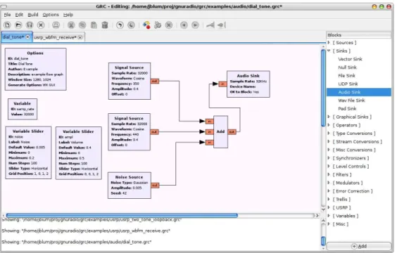
GRC is an open-source Visual programming language that uses the GNURadio li-braries, providing users an easy way to create GNURadio applications. Figure 2.3 gives a general idea of its interface. The GRC uses drag-and-drop to interact and define con-nections between the modules. GRC also provides information about the configuration of the system parameters, about its correctness, saving time and avoiding mistakes. When everything is set, GRC builds the python code, that runs the application. Thanks to the graphical and to the user-friendly interface, GRC offers an easy way of inserting and testing new modules in the system. However, GRC has some disadvantages and does not give place for block customization besides the configuration of the parameters, therefore GRC is not recommended for the implementation of a new module.
GRC is an interesting tool in an educational environment because it allows students to create and change GNURadio applications in a very short learning period. But in a research context, which needs more customization, GRC is not recommended because it slows down the research process. Instead, the researchers need to create new custom made blocks and add them to GRC, using the XML file that describes the module.
When creating new modules, it can be very difficult to create, compile and install all the files and folders necessary. For that purpose, GNURadio has a tool that allows an easy way to do it: thegr modtool. In the implementation chapter it is given a short tutorial on how to build new blocks step-by-step.
and have a cleaner signal. GNURadio provides several filters templates and a tool called
gr filter design and the users can design the filters using the parameters that GNURadio provides. More information about this tool is available in the implementation chapter.
Figure 2.3: GRC interface.
2.2
Block Transmission Techniques
This section starts by providing a brief comparison between Multi-Carrier (MC) and Single Carrier (SC) modulations, which are respectively, the base theoretical concept for the OFDM and SC-FDMA. Afterwards, this section explains each transmission techniques in detail.
2.2.1 Multi-Carrier and Single Carrier Modulations Comparison
s(t) =
N−1 X
n=0
snr(t−nTs), (2.3)
wheresnis the complex coefficient that matches thenth symbol, selected in a chosen
con-stellation (Phase Shift Keying (PSK), or a Quadrature Amplitude Modulation (QAM)); r(t) designates the support pulse with the proper constellation andTsthe symbol duration.
The Fourier transform to s(t) is given by,
S(f) =F{s(t)}=
N−1 X
k=0
snR(f)e−j2πf nT s. (2.4)
The transmission band for each data symbol sn, is equal to the band occupied by
R(f), which is the Fourier transform ofr(t).
The MC transmission sends theN symbols in the frequency-domain, each in a different sub-carrier, during the same interval of time (T). The multi-carrier signal assumes the following spectrum,
S(f) =
N−1 X
k=0
SkR(f−kF), (2.5)
where Sk refers thekth frequency-domain symbol, N the number of the used sub-carriers
andF = T1
s the spacing between sub-carriers. Doing the inverse Fourier transform to each
side of 2.5, leads to the dual of 2.4,
s(t) =F−1
{S(f)}=
N−1 X
k=0
Skr(t)e
−j2πkF t, (2.6)
which represents the complex envelope of the corresponding multi-carrier burst. Compar-ing all the above equations, it is clear that the multi-carrier modulation is dual to sCompar-ingle carrier modulation and the same way around.
mod-ulation method, gives no overlap between different sub-carriers in the spectrum. For the bandwidth of each Sk to be a fraction N1 of the total transmission band, the bandwidth
R(f) must be smaller than F (F is the bilateral bandwidth and F2 the unilateral band-width), as the figure 2.4 shows.
-2 -1 0 1 2
-3 3
f/F 1
Figure 2.4: Conventional FDM [Sil10]
The Inter-Symbol Interference (ISI) is a problem in this method. To prevent it, the pulse r(t) must verify the next orthogonality condition,
Z +∞
−∞
r(t−nTs)r
∗
(t−n′Ts)dt= 0, n6=n
′
. (2.7)
In the frequency-domain, the orthogonality condition between each sub-carriers is
Z +∞
−∞
R(f −kF)R∗
(f −k′F)df = 0, k6=k′. (2.8)
Z +∞
−∞
|r(t)|2e−j2π(k−k′)F t
dt= 0, k6=k′. (2.9)
In the SC modulation case, if we use different pulses using r(t− nTs) with n =
....,−1,0,1, ..., it still prevails the orthogonality between the pulses, even if they overlap. For example, using the pulse
r(t) =sinc
1 Ts
, (2.10)
with sinc(x), senπx(πx), the equation 2.7 is verified.
In the MC scheme the behaviour is identical and the orthogonality is still secure between the sub-carriers, even when we use distinct R(f −kF) and they overlap. For instance, the orthogonality between sub-carriers (expressions 2.8 and 2.9) still happens when,
R(f) =sinc
1 F
, (2.11)
that is equal to have in the time-domain a rectangular pulse r(t), with period T = F1 [Sil10]. This way, the orthogonality condition 2.9 now is
Z t0+T
0
e−j2π(k−k′)F tdt= 0, k6=k′
. (2.12)
2.2.2 Orthogonal Frequency Division Multiplexing
OFDM is a MC data transmission technique, where the data is transmitted on N
narrowband parallel sub-carriers, each using a portion of the available bandwidth and spaced each other by F > 1
TB (TB is the period of an OFDM block). So each block
fulfilling the orthogonality between them. This way, the complex envelope of an OFDM is given by,
s(t) =X
m
"N−1 X
k=0
Sk(m)ej2πkF t
#
r(t−mTB), (2.13)
which characterizes a sum of blocks with the durationTB>T, whereT = F1 (duration of
the useful part of the block) and they are transmitted at a rate of F > 1
TB. The N data
symbols, Sk;k = 0, ..., N −1, are sent during the mth block and the complex sinusoids,
ej2πkF t;k= 0, ..., N −1, denote the sub-carriers.
Consider the mth OFDM block. It can be expressed as
s(m)(t) =
N−1 X
k=0
Sk(m)r(t)ej2πkF t=
N−1 X
k=0
Sk(m)r(t)ej2πTkt, (2.14)
with r(t) being the transmitted impulse, where the time interval is bigger than T (TB =
T +TG),
r(t) =
1,[−TG, T]
0, elsewhere
(2.15)
the guard interval and is larger than 0. Although condition 2.9 is not verified by a pulse defined by 2.15, the orthogonality is still obtained in the time interval between [0, T], which is the effective detection interval. Each sampling instant is given by
s(m)(t) =
N−1 X
k=0
Sk(m)ej2πkF t,06t6TB. (2.16)
The symbol period must be longer than the delay spread through the time-dispersive radio channel.
s(m)(t) =
N−1 X
k=0
Sk(m)ej2πkF t=
N−1 X
k=0
Sk(m)ej2π
k
TBt=
N−1 X
k=0
Sk(m)ej2πkF t,06t6TB, (2.17)
with ej2πFkt;k = 0, ..., N −1 representing the sub-carriers, S
k;k = 0, ..., N −1 the mth
block data symbols, fk = TkB is the centre frequency of the kth sub-carrier and r(t) a
rectangular pulse with a bigger duration than F1 and equal to 1 in the interval [−TG, T].
Doing the inverse Fourier transform to both sides of 2.17, we get
S(f) =F{s(t)}=
N−1 X
k=0
Sk(m)sinchf−Tk
B i
. (2.18)
The duration of each symbol is big enough to insert a guard interval between each OFDM symbols, thus removing the Block Interference (IBI). To eliminate the Inter-Carrier Interference (ICI) we need to add a cyclic prefix instead of a zero interval [Sil10]. Equation 2.17, defines a periodic function in t with a period T. The guard period is the complex envelope of the final part of the MC block (figure 2.5). Therefore, the final part of the OFDM is copied to the beginning of the transmitted frame, the guard interval, creating a periodic signal and reducing the sensitivity to the time synchronization.
CP
OFDM Block
s(t)
t
Figure 2.5: MC cyclic prefix [Sil10]
the synchronization [vdBMSPOB97].
Assuming that there is a block containing the data samples plus the cyclic prefix, with a size ofNG+N, using the ML synchronization, we observe a 2N+NGsize window,
that certainly contain one complete OFDM NG+N symbol. By performing a series of
operations, the ML gives the estimation of ˆεM L, which is the carrier offset, and ˆθM L that
represents the channel delay estimation [vdBMSPOB97].
PN synchronization searches for a training symbol with two identical halves in the time-domain. The two halves remain identical after passing through the channel, except for phase differences, caused by the carrier frequency offset. The training symbols have the PN sequence in the even frequencies while the odd are zero by default. An accurate estimation of the carrier frequency offset and of the symbol timing. PN allow a very fast and low-overhead synchronization, which is necessary for wireless communications [SC97].
Transmission Scheme
When the data symbols enter in the OFDM transmission block, it is first converted in a serial to parallel converter. Thus, they are transformed intoN size data blocks, represented asSk;k= 0, ..., N −1, which are complex data symbols from a chosen constellation (PSK,
QAM, etc.). Taking 2.17 and sampling the OFDM symbols with a interval, Ta = NT, we
get the samples,
sn≡s(t)|t=nTa =S(t)δ(t−nTa) =
N−1 X
k=0
Skej2π
k
TnTa, n= 0,1, ..., N −1, (2.19)
where F = T1. An IFFT is applied to the data blocks, to pass them to the time-domain, so 2.19 can be written as
sn= k=0
X
N−1
Skej
2πkn
N =IF F T{Sk}, n= 0,1, ..., N−1. (2.20)
Then, a cyclic prefix is added, with NG samples size, which are inserted at the
the OFDM block. It is bigger than the channel impulse response and is attached between each block, transforming the multipath linear convolution into a circular one. With the cyclic prefix, the data block issn;n=−NG, ..., N−1 and the time duration of the OFDM
symbol is NG+N times larger than the symbol of a SC modulation. The cyclic prefix
increases the cost and bandwidth, because it adds additional data. After adding the cyclic prefix, the data is converted from parallel to serial, a DAC is applied and the data is sent through a designated channel. The OFDM modulator block is depicted in figure 2.6.
Mapper IFFT Add CP
DAC
DAC
S ...
Figure 2.6: OFDM modulator block [Sil10]
Reception Scheme
ADC
ADC
Low-pass
Filter Sync
Remove CP
... FFT ... FDE Decision Device
Y
Figure 2.7: OFDM demodulator block [Sil10]
The signal that enters in the reception block, y(t), is the convolution ofs(t) with the channel response h(τ, t) plus the noise signaln(t), and comes in the form of
y(t) =
Z +∞
−∞
s(t−τ)h(τ, t)dτ+n(t). (2.21)
The signaly(t) is then submitted to an ADC, converting it into the sequenceyn, where
n=−NG, ...., N−1, which corresponds to the sampled version of the received signal y(t)
with a sampling rateTa= NT. The signal received is then filtered, by a low-pass filter, and
enters in the synchronization block, which applies PN or ML synchronization [Ram08]. The received data symbols may overlap, due to multipath propagation, which leads to a loss of orthogonality between sub-carriers. The usage of the cyclic prefix with a duration TGlonger than the channel impulse response avoids the overlapping. The sequence received
hasN+NGsamples due to the cyclic prefix in theNGfirst samples, which is extracted in
the next step. After this operation, the resulting samples are converted to the frequency-domain using the FFT algorithm. The frequency-frequency-domain block Yk;k= 0, ...., N−1, is
Yk = N−1
X
k=0
yne
−j2πkn
N , k= 0,1, ..., N−1. (2.22)
Since IBI is prevented using the cyclic prefix, the receiver works each sub-carrier individually. Considering flat fading on each sub-carrier and null ISI, the symbols are characterized in the frequency-domain by
Yk=HkSk+Nk, k= 0, ..., N −1, (2.23)
where Nk represents the additive Gaussian channel noise and Hk the overall channel
frequency response for the kth sub-carrier.
The OFDM sub-carrier has a narrow bandwidth when the number of sub-carrier is sufficiently large. A constant frequency-selective effect can occur, which is caused by the fading effect due to multipath propagation. In this case, the equalizer has to multiply each sub-carrier by a constant complex number. This equalization is simpler and consumes less computational process if it is done in the frequency-domain rather than in the time-domain, this is why the receiver uses an FFT to convert theN size blocks to the frequency-domain. When the receiver obtains theYk samples, the equalization occurs using a Frequency
Domain Equalization (FDE). It may consist in a simple one-tap equalizer under the zero forcing (ZF) criteria, where the samples are outputted as
˜
Sk =FkYk. (2.24)
˜
Sk denotes the estimated data symbols, calculated from the multiplication of the
inputted symbols and the equalization coefficients, Fk;k= 0, ..., N −1 defined by
Fk=
1 Hk
= H
∗
k
|Hk|2
After the equalization, the decision device works, and based on the constellation, does the demodulation of the samples [Sil10].
2.2.3 Single Carrier - Frequency Division Multiple Access
In the 3rd generation in wireless telecommunication systems, OFDM was the official
modulation technique used for transmission, because it could achieve high bit rates. With the evolution to the new generation, Long Term Evolution (LTE), Single Carrier - Fre-quency Division Multiple Access (SC-FDMA), also referred as precoded-OFDM or DFT-Spread OFDM, takes a step in and is the new modulation technique used for the uplink wireless transmission. This technique uses different sub-carriers to transmit the symbols, but this time, the transmission of the sub-carriers is done sequentially, rather than in parallel, reducing the envelope fluctuations in the transmitted waveform [HGMG06].
The choice for SC-FDMA in LTE comes from the need to reduce the Peak-to-Average Power Ratio (PAPR), which in OFDM is greater than SC-FDMA, making OFDM un-favourable for the uplink transmission [Ahs09]. The wireless systems have severe multi-path propagation, making SC-FDMA signals arrive at the base station with inter-symbol interference, but the base station cancels the interference by applying an adaptive FDE.
Terminal 1
Terminal 2
Terminal 3
Sub-carriers
Localized Mode Sub-carriers
Distributed Mode
Figure 2.8: Sub-carrier allocation (Distributed mode and Localized mode) [HGMG06]
Transmission Scheme
Figure 2.9 shows the transmitter block, explained in this subsection.
N-size
DFT
Sub-carrier Mapping
M-size
IDFT
CP adder /
PS
DAC/RF
Channel
Figure 2.9: SC-FDMA modulator block
Like in the OFDM transmitter, the SC-FDMA transmitter first converts a binary input signal into a multilevel sequence of complex numbers sn, using the proper constellation
(BPSK, QPSK, 8PSK or 16/64QAM), which may differ, to match the current channel conditions. Then the stream of complex numbers enters in a serial to parallel converter. We get, in the end, the same result as the OFDM counterpart in equation 2.19. The passage of the symbols from the time-domain to the frequency-domain (Sk) is done applying a
standard preamble used in OFDM [SB09]. The Chu-sequence used for the LTE systems has the following formula,
sk=e
−jπRk(k−1)
N , k= 0, ..., N −1, (2.26)
where R is the root of the Zadoff-Chu sequence and N the length. In order to perform a good synchronization, this sequence is interleaved with zeros, like in the OFDM preamble system, in order to perform a good synchronization [3GP08].
From this point on, the modulator performs the sub-carriers mapping, using either IFDMA or LFDMA, mentioned above. The sub-carriers are mapped into blocks, with a size M, where M must be greater than N and N = M
Q (Q is the bandwidth expansion
factor of the symbol sequence). The result of this mapping is expressed by ˜Sl (with
l= 0, ...., M−1).
In the next step, it is performed aM −size inverse Fourier transform (IDFT) to ˜Sl,
converting the symbols to the time-domain, ˜sm. A chosen frequency carrier is used to
carry all the modulated symbols, which are then sent sequentially.
Like in OFDM, the problem with IBI, caused by multipath propagation, is resolved by adding the cyclic prefix, with a size larger than the length of the channel impulse response. The additional symbols, at the beginning of the sequence, are also copied from the end of the block, similarly to the OFDM, which converts a discrete time linear convolution into a discrete time circular convolution. After adding the cyclic prefix, the signal is converted from parallel to serial, it is applied a DAC and the signal is sent through a designated channel [HGMG06].
Reception Scheme
To follow this sub-section, figure 2.10 shows the internal blocks of the demodulation block.
power. Depending upon the rolloff factor of the filter pulse, which convolves with the signal, the filter induces a distortion in the signal, causing an increase in PAPR. However, this does not mean that the PAPR of the SC-FDMA is higher than the OFDM, because even in the worst case scenario, the PAPR for the SC-FDMA is lower then the OFDM signal [Han09].
Detect Sub-carrier
Demapping/ Equalization M-size
DFT Remove
CP ADC/RF
Channel
N-size DFT
Figure 2.10: SC-FDMA demodulator block
Next, the signal enters in the synchronization block, which transforms the stream of symbols into blocks, that have a M+NG size (NG is the guard size). The cyclic prefix is
removed, resulting in M size blocks, ready for the equalization, but before this, a M size Fourier transform is applied to the data blocks, converting them from the time-domain to the frequency-domain, to simplify the equalization. The resulting SC-FDMA blocks are defined by the following equation,
Yk=HkSk+Nk, k= 0, ..., N −1, (2.27)
whereHkis the overall channel frequency response for thekthsub-carrier andNkrepresents
the additive Gaussian channel noise. ISI can also occur in the SC modulation. Yk is
Fk=
H∗
k
α+|Hk|2
, k= 0, ..., N −1, (2.28)
where α represents the inverse of the Signal to Noise Ratio. Fk coefficients multiply the
System Implementation
The GNURadio platform and the theory behind OFDM and SC-FDMA modulators were described in the previous chapter. This chapter focuses on the implementation of the SC-FDMA modulator and demodulator blocks and also shows how the tools in GNURadio work.
This chapter is organized as follows: section 3.1 starts by presenting examples of GRC software; section 3.2 shows how to create new blocks and design the filters, using the
gr modtooland gr filter designtools respectively; section 3.3 reveals how the OFDM tech-nique is implemented in GNURadio, analysing the modulator and demodulator blocks; and section 3.4 explains the SC-FDMA modulator and demodulator blocks implementation.
3.1
Dial Tone Example
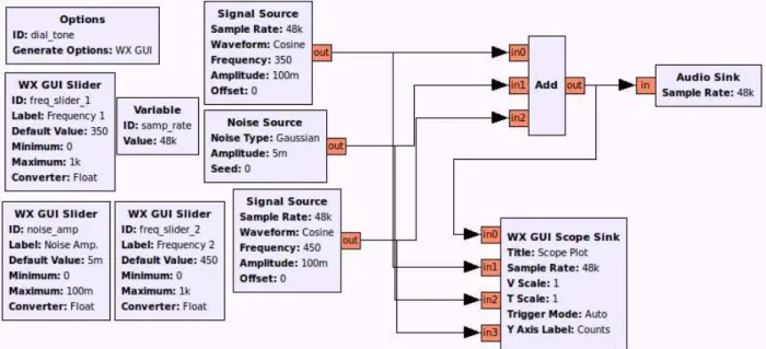
This section presents the Dial Tone example implemented using the GNURadio plat-form. This example produces an audio sound composed by two cosine signal sources and by a noise signal source. The output is converted to an audio format using the audio sink block, allowing the signal to be heard. Figure 3.1 shows the schematic for this example, on the GRC. First, the Signal Source block creates cosine waves; the frequency is adjusted using a WX GUI Slider, a variable slider that ranges from 0 to 1000; the amplitude of the wave is set to 0.1. There are two Signal Sources: one with the default frequency of 350 Hz and another with 450 Hz. The Noise Source block creates a Gaussian noise; this block also has a WX GUI Slider associated with the noise amplitude that ranges from 0 to 0.1
and has a default value of 0.005. The three source blocks are added, using an Add block, and the output enters in the Audio Sink block. To analyse the signal in the time domain, all blocks are connected to the channel plotter block WX GUI Scope Sink, which works like an oscilloscope and shows the inputted signals in the graphical interface.
Figure 3.1: Dial Tone example - block diagram.
After connecting all the ports in the GRC schematic, the program generates the python code listed in appendix A. Two experiments were done with the setups from table 3.1, generating the graphs depicted in figure 3.2. They show four channels and each channel represents an input signal. Channel 1 is the final signal, channel 2 is the signal from signal source 1, channel 3 is the noise signal and channel 4 is the second source signal. As observed in figure 3.2, the signal in channel 1 increases as the other two increase and decreases if the other two diminish. The difference between the two graphs is the noise added to the two source signals.
❵ ❵
❵ ❵
❵ ❵
❵ ❵
❵ ❵
❵
Parameters
Setup
1 2
Signal Source 1 Frequency (Hertz) 450 100 Signal Source 2 Frequency (Hertz) 750 600
Noise Source Amplitude 5m 30m
Figure 3.2: First Examples graphs - Upper graph - experiment 1. Bottom graph - experi-ment 2.
3.2
GNURadio Tools
GNURadio provides tools to assist the signal processing. First, the gr modtool eases the creation of new modules in C++; this section has a step-by-step guide on how to create new modules on GNURadio. The second part shows thegr filter design, how it works and which filters can be designed by this tool. The operating system used to perform the tests and the implementation is Ubunto 12.04.
3.2.1 Creating New Blocks (gr modtool)
Creating new blocks is a hard process. To smooth it, GNURadio offers a tool called
gr modtool, which creates all the folders and the skeleton files for C++.
The first step in the creation of a new block is to create a new module. In the terminal, you may call:
Then the terminal asks for the module name (let us call itexp) and generates a folder with the namegr-exp. This folder contains all the necessary sub-folders and files to compile the new blocks the user may add. In order to create new blocks, inside the folder gr-exp, you may call:
1 ✩gr modtool add
Now, the terminal asks which block type the user wants to create (it can be a sink, source, sync, decimator, interpolator, general, hier, noblock). Next, the terminal asks for the block name (let us call it “square ff”) and for the input arguments. Finally, the terminal asks if the user wants to define test codes. When the terminal finishes creating all the files and folders, it is time to program them. There are two main files that can be modified to do the signal processing; square ff impl.cc and square ff impl.h (both in
lib folder). There is also an XML file (exp square ff.xmlin the grc folder) that should be modified to prepare the block for the GRC software. Appendix B shows the modification performed in order to create a block that computes the square of the inputted signal.
With the files completely programmed, it is time to compile them; from the terminal in the gr-expfolder, you should call:
1 ✩mkdir build 2 ✩cdbuild 3 ✩cmake../ 4 ✩make
5 ✩sudo make install 6 ✩sudo ldconfig
This sequence of commands creates a folder named buildand compiles the files inside it. While running themakecommand, there might exist some errors in the C++ code and the terminal alerts for them. When everything is correct, the user can access the blocks in GRC, and it is also possible to call the new blocks in python flowgraphs.
3.2.2 Filter Design Tool
pass, band notch, high pass, root raised cosine and gaussian filters. To create the filter, there are several window functions such as: Blackman, Blackman-Harris, Hamming, Hann, Rectangular, Kaiser and Equiripple; these functions produce zero values outside of their interval and all that is left is the part where they overlap with the signal.
The application has a friendly user-interface, represented in figure 3.3. On the upper left side, the user can choose from the several filter types and windows functions. The variables below change according to the user choice, and allow the configuration of the filter’s and window’s parameters. The graph on the right shows the frequency response and time domain representation of the filter as well as the phase and group delay.
Figure 3.3: GNURadio Filter Design tool interface.
Root Raised Cosine Parameters Sample Rate (sps) 2M
Filter Gain 1
Symbol Rate (sps) 1M Roll-off Factor 0.01 Number of Taps 201
Table 3.2: Parameters to design a Root Raised Cosine filter.
Figure 3.4: Root Raised Cosine filter performance graphs
3.3
OFDM Block
GNURadio package already includes two OFDM blocks; the modulator and demodu-lator blocks. Both are explained in detail in this section.
or 8/16/64/256 QAM). These parameters have to be equal in both, sender and receiver. There are other parameters that only belong tobenchmark tx.py, like the size and number of packets that are transmitted. When using the benchmarks, the experiments require the use of an USRP. This way, there is another parameter that defines the antenna used by the system. When the user calls the benchmarks in the terminal, he must choose which antenna is used; for the sender the user must writeRX/TX and for the receiverRX2.
The benchmarks are in the top of the OFDM block hierarchy. Bellow them there are other two python files. The transmit path.py file, which creates the schematic using the OFDM modulator block and helps in the definition of some parameters; and the
receive path.py, that besides creating the schematic, has a module called probe that detects if there is transmission.
To create the OFDM modulator and demodulator blocks, GNURadio uses the python file called ofdm.py (located in the gr-digital/python folder), this file defines two classes: the ofdm mod for the modulator and the ofdm demod for the demodulator. Figure 3.5 shows how the blocks appear in the GRC. The blocks have several parameters such as: modulation, where users may choose a constellation (BPSK, QPSK, 8PSK or 8/16/64/256 QAM); FFT length (M), necessary for the IFFT and FFT algorithms; cyclic prefix length and occupied tones (N).
Figure 3.5: GRC OFDM blocks.
The next two subsections explain the OFDM modulator and demodulator classes in detail. This way, our implementation of the SC-FDMA blocks can be easier to understand. Appendix C shows the most relevant code of the OFDM blocks.
3.3.1 OFDM Modulator Block
The OFDM modulator block is created in the ofdm.py file, at the ofdm mod class. This module defines two main functions: one for changing the options and other to create messages, thesend pkt function. Function send pktcreates data blocks with the inputted data using the function make packet, from ofdm packet utils. The blocks have a header, which is used at the receiver to check its validity, and a body. The created packets are then put in a queue.
Figure 3.6 shows the OFDM modulator block schematic. Each module in the figure represents a member of theofdm modclass, and underneath them are the file names where the modules are programmed. As we can see, the modulator is composed by the following modules: pkt input, preambles, ifft, cp adder and scale. These modules are connected by one OFDM data stream, except for the first two modules that are connect by an additional data stream.
Msg queue
preambles ifft cp_adder scale
pkt_input self
0
1
Label: 0 – OFDM data 1 – Str eam of characteres
0 0 0 0
ofdm_mapper_bcv ofdm_insert_preamble gr.fft_vcc ofdm_cyclic_prefixer gr.mult iply_const_cc
Figure 3.6: Block diagram of the OFDM modulator.
Normally, in a python block where several modules are connected between them, we use the function connect(self, <module >), so that the first module receives the data directly from the block input port. Because the OFDM modulator receives input data from a message queue, the first connection does not start with self, but with the first module,
pkt input. This module withdraws the messages from the message queue and works with them. We can see how the modules are connected in ofdm mod class in appendix C list C.3.
module receives the messages as data input and has two output ports: one port outputs the data blocks, with M symbols in each block; and the other port outputs a stream of characters delimiting the block, one for each OFDM data symbol outputted. The character outputted is 1 when it is the first symbol of the block and 0 for the remaining symbols. The character stream is consumed by the next module, which uses them to insert the preamble block in the right position. There are two important input parameters in this module:
❼ d occupied carriers - sets the size of the d subcarrier mapvector;
❼ d fft length - sets the size of the outputted data blocks.
As the number of blocks outputted is higher than the size of d subcarrier map, the rest of the outputted data block is initialized with zeros. Figure 3.7 shows how the data blocks are filled. We can see that each block has M symbols but only N symbols have useful data, whereM represents the FFT length andN the occupied tones length. When the pkt input module is initialized, it calculates the sub-carriers tones and saves them in thed subcarrier mapvector. Later, the module uses the vector to map the data inside the output data blocks.
0 0 0
. . .
0 0 0
1 1-1
-1
. . .-11 1-1
0 0 0
. . .
0 0 0
N
M
Figure 3.7: Data allocation inside each block.
As stated above, thepkt inputmodule works using messages as inputted data, drawing the messages from the message queue. The module uses the selected constellation (BPSK, QPSK, 8PSK or 8/16/64/256 QAM) and modulates the symbols inside the messages. There are some cases where the data is not enough to complete the data blocks, therefore the module uses the function randsym to randomly generate data symbols to fill them.
known sequence of symbols constructed from a vector of′
1′
and′ −1′
previously generated. The sequence enters has an input parameter and it is stored in d preamble vector. The
preamblesmodule has two data input ports: in the first port enters the data blocks withM symbols; and in the second port enters the stream of characters outputted by the previous module. When the preambles module finds the character ′
1′
in the stream, it adds one preamble block and outputs the rest of the data blocks, until it finds the character ′
1′
again. More details on this module are explained in the SC-FDMA modulator subsection, which also uses it. Thepreamblesmodule output ports have the same size as the previous block, but only the port that outputs the data blocks is connected to the next block, the
ifft module.
Theifftmodule takes the data blocks and does the inverse Fourier transform, convert-ing the symbols from the frequency-domain to the time-domain. IFFT and FFT blocks are defined in the C++ file gr fft vcc.cc, which is a GNURadio generic block. The last two modules were specifically developed for the OFDM computation.
In the next step the modulator adds the cyclic prefix. This operation is performed in the cp adder module and is defined in the C++ file digital ofdm cyclic prefixer.cc. This module uses the inputted data blocks and copies the last symbols of the block to the begin. The length of the copied symbols is equal to the cp size parameter, which is an input parameter. Now, the blocks have the length of the inputted data blocks plus the length of the cyclic prefix. In the end, this module converts the blocks into a stream of symbols in order to send them later.
3.3.2 OFDM Demodulator Block
The OFDM demodulator block is also created in the ofdm.py file, this time in the
ofdm demod class. Figure 3.8 illustrates the demodulator block diagram. This block has two modules: ofdm recv and ofdm demod. The demodulator uses the input port self to receive the data, which comes in the form of complex numbers. Then, in the ofdm recv
module, the demodulator implement the functions (filter, synchronization, de-mapping and equalization) necessary to recover the symbols. Finally, using the ofdm demod module, the block demodulates the data symbols, comparing them with the constellation in use; and possibly recovering the binary messages sent by the modulator.
Msg queue
ofdm_demod
self
0
1
ofdm_recv
Label:
0 – OFDM data
1 – Str eam of characteres ofdm_receiver.py ofdm_frame_sink
Figure 3.8: Diagram of the OFDM demodulator.
The demodulator block receives the stream of complex data, coming from an USRP sink or from a Channel Model, respectively for a hardware implementation and for a sim-ulation on GRC software. The data enters in the ofdm recvmodule, which is created in a different python file named ofdm receiver.py. Figure 3.9 shows the block structure in the
ofdm receiver.py. Each module in the figure represents its name inofdm receiver.py and the file name where the module is programmed. The ofdm recvblock is composed by the
nco sigmix ofdm_sync chan_filter self 0 1 Label: 0 – OFDM data
1 – Str eam of characteres
fft_demod ofdm_frame_acq sampler ofdm_sync_pn.py gr.frquency_modula tor gr.mult iply_cc gr.firdes.low_pass ofdm_sampler.cc ofdm_sampler.cc ofdm_fra me_acquisition.cc 0 1 0 0 1
Figure 3.9: Block diagram of ofdm receiver.py.
The first module ischan filt, which is a low-pass filter with a Hamming Window. The filter parameters depend on the FFT size (M) and the occupied tones (N) size. The filter gain and sampling rate are fixed to 1, the cut-off frequency isBW = 2NM and the transition width is T B = 0.08BW
After the filter, the data stream enters in the synchronization module ofdm sync. There are several implementations for this module: the maximum likelihood synchro-nization (ofdm sync ml), defined in the python code ofdm sync ml.py; the pseudoran-dom noise numbers synchronization module (ofdm sync pn), defined in the python code
ofdm sync pn.py; the enhanced pseudorandom noise synchronization module (ofdm sync pnac), defined in the python codeofdm sync pnac.py; and the fixed synchronization mod-ule (ofdm sync fixed), defined in the python codeofdm sync fixed.py. This OFDM demod-ulator block uses theofdm sync pnmodule as the default module for the synchronization. The module ofdm sync pn is based on the Schmidl and Cox algorithm [SC97]. This algorithm searches for the beginning of the training symbols and calculates the frequency offset. To run this algorithm, the preamble sequence must come with a predefined arrange-ment. For this reason, when the modulator inserts the preamble block, the symbols were originally put on the even carriers and the zeros on the odd carriers. The modulator’s ifft
IFFT
V 0 W 0 X ... 0 Y 0 Z 0
CP K K
Figure 3.10: Result of the preamble block conversion.
When the ofdm sync pn module obtains a preamble sequence, the first and second half only differ on a phase shift. If the transmitting channel is constant during an interval T, if we multiply the conjugate of each symbol in the first half with the corresponding one in the second half, we cancel the effect of the channel and get the following phase,
φ=πT∆f. (3.1)
If we consider that half of the preamble block has L symbols, we can sum all the symbols within a window of 2Lsymbols. Resulting in,
P(d) =
L−1 X
k=0
r∗
d+krd+k+L
, (3.2)
wheredis the time index. The module calculates the received energy for the second half, using
R(d) =
L−1 X
k=0
|rd+k+L|2. (3.3)
M(d) = |P(d)|
2
(R(d))2 (3.4)
When the module calculates the timing metric, the result values are bellow 1. Now, the module uses a peak detector to find the maximum value, which detects the starting carrier of the data block. So, in one port the ofdm sync pn module outputs a stream of
′
1′
and ′
0′
characters, coming from the peak detector, where ′
1′
represents the beginning of the OFDM data blocks and the′
0′
the rest of the symbols.
Besides giving the start of the preamble block, this module gives the frequency offset estimation ( ˆ∆f) and uses it to correct the diverted symbols. This way, using 3.1 we can estimate ˆφas,
ˆ
φ=angle(P(d)). (3.5)
Thus, getting
ˆ ∆f = φˆ
πT. (3.6)
So, from the second output port in theofdm sync pnmodule we get a stream of floats, each representing a frequency offset. This port connects to the nco module [Pag06].
The ncomodule, defined in the C++ file gr frequency modulator fc.cc, is a frequency modulator that generates a signal proportional to the frequency offset. The outputted complex data multiplies with the outputted signal from the filter, thus making the fre-quency correction of the signal; this multiplication is done in thesigmix, a simple multiplier module.
Later, for the SC-FDMA demodulator we will use the same synchronization module and thenco and sigmixmodules, with a little modification in the peak detector.
module, defined in the C++ fileofdm sampler.cc. The sampler module receives the data stream coming from sigmixmodule and the character stream from theofdm syncmodule, removes the cyclic prefix and creates the data blocks. The module has two output ports: the first outputs the data blocks and the second a stream of characters. In this case, the character ′
1′
indicates the preamble block and ′
0′
the data blocks.
The next step is a Fourier transform done by the fft demod module. This module converts the data blocks from the time-domain to the frequency-domain. The outputted data enters in the first port of ofdm frame acquisition.
Theofdm frame acquisitionmodule is defined in the C++ filedigital ofdm frame acquisition.cc. The module searches for the start of the OFDM data block based on the inputted
charac-ters. At the same time that the module finds an ′
1′
character, the preamble block enters in the other input port. Using this data block, the module searches for the start of the occupied tones with thecorrelatefunction, because the carriers may or may not be shifted. When the data blocks enter in the FDE module, they have the following expression,
Yk=HkSk+Nk, k= 0, ..., N −1, (3.7)
whereYk represents the inputted samples,Nk the additive Gaussian channel noise,Skthe
known symbols and Hk the overall channel frequency response for thekth sub-carrier. To
calculate the frequency response, we use the expression,
Hk =
Yk
Sk
, k= 0, ..., N−1, (3.8)
assuming that we ignore the additive noise. At this instant, when the following data blocks enter in FDE module, we need to multiply them by Fk, to perform the equalization. This
way, we use the expression,
˜
where Fk= H1k orFk= SYkk.
With this in mind, the ofdm frame acquisition module enters in the function calcu-late equalizer and using the preamble block, calculates Fk, with the following formula,
d hestimate = d known symbol
symbol , (3.10)
where d hestimateis Fk,d known symbolis Sk and symbolis Yk.
After the preamble block, the next blocks have data symbols. Using the equation 3.9, these data blocks suffer a one-tap equalization on all sub-carriers by multiplying the received samples by the values in d hestimate, using the expression
out =d hestimate∗coarse freq comp∗symbol (3.11)
where out is ˜Sk, d hestimate is Fk and symbol is Yk. When there is a carrier offset,
the function coarse freq compobtains the complex value that restores the samples to the original carrier, otherwise coarse freq compwill give the value of 1.
Eventually, the module finds a new character ′
1′
and it starts the process again for a new OFDM data block. The ofdm frame acquisition module only copies the occupied sub-carriers from the data blocks and outputs only the necessary data.
SYNC
SEARCH
HAVE
HEADER
HAVE
SYNC
Data demod don eBlock found
Header foun d
ERROR
ERROR
Data
Queue
Data
Figure 3.11: State machine in theofdm demod module.
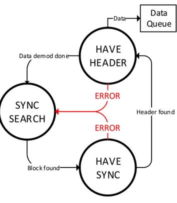
The state machine inofdm demodmodule starts in state SYNC SEARCH. The module waits in this state until a flag 1 is received in the second port, signalling the beginning of an OFDM data block. Following this event, the module enters in the HAVE SYNC state and ignores the preamble data, demodulating only the symbols corresponding to the header. The header is build in a way that the first and the last half have the same data. If the header is found, the module enters in the HAVE HEADER state, demodulates the rest of the OFDM data and creates a new messages, returning in the end to the state SYNC SEARCH. The resulting messages are queued and taken to the upper levels, if the data is valid. Therefore, this module is constantly searching for the start of the next OFDM data block.
![Figure 2.6: OFDM modulator block [Sil10]](https://thumb-eu.123doks.com/thumbv2/123dok_br/16578818.738401/38.892.158.778.469.714/figure-ofdm-modulator-block-sil.webp)
![Figure 2.7: OFDM demodulator block [Sil10]](https://thumb-eu.123doks.com/thumbv2/123dok_br/16578818.738401/39.892.155.732.141.487/figure-ofdm-demodulator-block-sil.webp)