Energy Efficiency of MIMO-OFDM Communication System
K.Swathi
1, S Mallikarjun Rao
21
(Department of E.C.E, Andhra Loyola Institute of Engineering and Technology, Vijayawada, India)
2
(Assistant Professor, Department of E.C.E, Andhra Loyola Institute of Engineering and Technology, Vijayawada, India)
ABSTRACT
With the ever increasing number of subscribers and their seemingly “greedy” demands for high-data-rate services, the next generation networks will have to provide global connectivity to ensure success. So the combination of multiple-input multiple-output (MIMO) signal processing with orthogonal frequency division multiplexing (OFDM) is regarded as a promising solution for enhancing the data rates of next-generation wireless communication systems operating in frequency-selective fading environments.
Therefore hybrid architecture between terrestrial and satellite networks based on MIMO-OFDM with frequency reuse is employed here. However, this frequency reuse introduces severe co-channel interference (CCI) at the satellite end. To mitigate CCI, we propose an OFDM based adaptive beamformer implemented on-board the satellite with pilot reallocation at the transmitter side. The system performance is simulated by using the software MATLAB, the experimental result shows that the MIMO-OFDM communication system has better performance when compared.
Keywords
: Adaptive beamforming, Co-channel interference (CCI) Multiple-input multiple-output (MIMO), Orthogonal frequency division multiplexing (OFDM).I.
INTRODUCTION
In today’s world the need for communication has
driven the growing demand of multimedia services and the growth of Internet related contents lead to increasing interest to high speed communication with higher data rates and all time connectivity. This increased a lot of pressure on the communication networks. In order to meet this requirement a well sophisticated technological communication networks are needed. For a communication network to be effective provision of higher data rates is not alone sufficient but it has to support a large customer base.
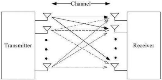
In order to deal with this problem, a hybrid architecture based on OFDM system using MIMO is modeled and is presented in Fig 1. In this architecture the users located in rural areas are served directly from the satellite spot beam due to lack of infrastructure of terrestrial networks [2] [3]. On the other hand users located in urban areas are served by existing terrestrial system as satellite signal cannot penetrate in buildings [4]. Likewise, the spectrum is being shared between two networks that is terrestrial and satellite for providing throughout connectivity and the multiple antennas at the transmitter and the
receiver (MIMO) provide high data rates at reasonable cost.
The rest of this paper is structured as follows: Section 2 gives the OFDM with MIMO. Section 3 describes the system modelSection 4 presents Simulation results obtained using MATLAB and the results are discussed with reasons. Section 5 presents Conclusion and References are given in last section.
II.
MIMO-OFDM
Today’s communication environment the signal
is propagating from the transmitter to the receiver along number of different paths collectively referred as multipath. The use of multiple antennas at both the transmitter and receiver is commonly referred as multiple-input multiple-output (MIMO) is shown in Fig 2 which improves communication performance and one of several forms of smart antenna technology [2]. MIMO technology has attracted attention in the field of communications, because it offers significant increases in data throughput and link range without additional bandwidth or transmit power. It achieves this by higher spectral efficiency (more bits per second per hertz of bandwidth) and link reliability or diversity (reduced fading).
Figure 1: Hybrid Terrestrial-Satellite System.
Figure 2: Basic MIMO model.
OFDM is found to be a popular method for high-data-rate transmissions. It may be combined with multiple antennas at both the access point and receiver section to increase diversity gain and/or enhance system capacity on a time-varying multipath fading channel, resulting in a MIMO-OFDM system. The combination MIMO-OFDM is very natural and beneficial since OFDM enables support of more antennas and larger bandwidths since it simplifies equalization dramatically in MIMO systems and it is regarded as a promising solution for enhancing the data rates of next-generation communication systems supporting a large customer base.
III.
SYSTEM MODEL.
frequency domain of multiuser case is expressed as, taking one symbol at a time.
x(i, j)=( x(1,j), x(2, j),…… x(N, j) )T (1)
Where x(N, j) shows the nth subcarrier of the jth user,
where n = 1, 2, 3, . . . . , N and j = 1, 2, 3, . . . , J and (.)T represents the transpose.
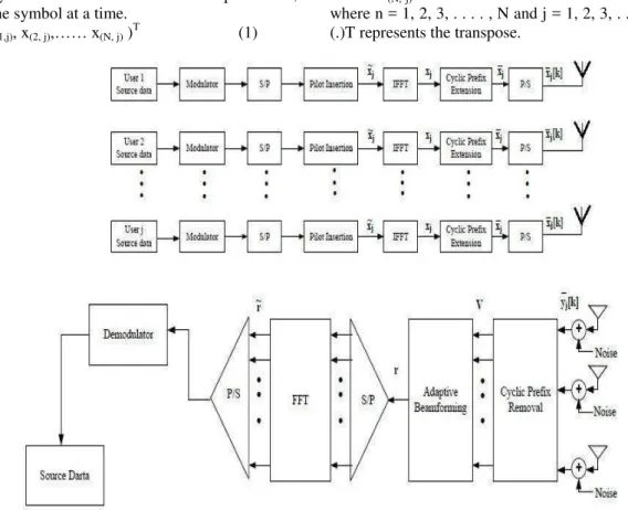
Figure 3: MIMO-OFDM System model.
Now the mapped data signal is in frequency domain is transformed into time domain by using IFFT.
xj = FHxj (2)
Eq.2, is the time domain symbol of an OFDM system and F shows the matrix for FFT operation and (.)H shows the Hermitian transpose. After the transformation of signal from time domain to frequency domain, then comes the block of cyclic prefix extension to overcome the effect of ISI (Inter Symbol Interference) [7][8].The guard interval is introduced using the following equation [9].
xj= KFH N,G
N (3)
In (3),��=[G+1,j), G+2,j), . . . . , x(N-1,j), x(N ,j), x(x(N-1,j), x(2,j), . . . . , x(N,j)]T is the OFDM symbol with the cyclic prefix of 1/4th of the symbol lengthand N,G in (3) is containing the last G rows of matrix IN, which is an identity matrix of size N. After
this the parallel to serial converter (P/S) converts the data to serial form and readily transmits over the channel. Channel effect can be expressed as [9].
yj= xjNhjk (4)
Where k is the index of time in (4), so passing through the channel, the signal is received by the receiver from the desired source and other sources of interference. In this paper the channel effect is not
considered. When the signal is received at the satellite antenna element, the signal matrix for one OFDM symbol after removing the cyclic prefix can be represented as [10]
V = AYH+ N(5)
In (5); A is the array response, Y is the received OFDM symbol and N is the noise. The important point to notice here is that the beamformer will take one OFDM symbol at time so the noise for that one symbol will be randomly generated.
Similarly the received signal for jth user and nth subcarrier is given by y(j, n) i.e., is the element of Y matrix. Also n(s, n) and v(s, n) are the elements of matrix N and V respectively representing the noise and output of beamformer for sth antenna element and nth OFDM subcarrier and the element of A matrix which is the array response of sth antenna elements and jth user is given by(6).
a s, j = ej2Πsλdsnθ
(6)
Where the total number of antenna elements are s = 1, 2, 3, . . . ,S. And the inter antenna element distance is given by d, and the direction of Arrival (DOA) for the jth user is given by θjand the carrier wavelength is given by λ. Since we have modeled the linear array so the distance between inter-elements is da= λ/2, the
Beamforming (BF) is a type of spatial filtering provided by a array of antenna elements to mitigate interference.
Use of BF (spatial filtering) with array of antenna elements offers two principle advantages: 1) In view to the CCI problem, the capability of interference mitigation is directly proportional to the size (or length) of the spatial aperture. An array of antenna elements or sensors is able to synthesize a much larger spatial aperture as compared to a single physical antenna.
2) The more important advantage is that BF gives the ability to performactive signal suppression. This can be done by adaptively changing the spatial filtering functions to effectively track the desired user and mitigate the interference.
A beamformer is analogous to anFinite impulse response (FIR) filter in the sense that an FIR filter linearly combines temporally sampled data whereas a beamformer linearly combines spatially sampled data. Therefore, beamformer response can be defined as a function of location and frequency.
The beamformer processes the output of the antenna elements by applying complex weights to the symbols. The complex weights of the beamformer can only be considered as a constant value if the statistics of the signal at the input of the beamformer remain unchanged. In wireless communication systems, the users are not bound to a constant position. Moreover, users can be present in any location within the service region and hence weights cannot be hard-wired. Hence the beamformer should have the capability of changing its weights depending on the DOA of desired and interference signals. This requires computation of weights at frequent intervals and the subsequent class of BF is referred to as adaptive BF and this process is expressed as
r = wHV (7)
where r in (7) is termed as the weighted beamformer output and r = [r(1), r(2), . . . . , r(N)] and w is [w(1), w(2), . . . . , w(N)]T termed as complex weights. After the beamformer, the received datais applied to serial
to parallel (S/P) converter and is converted into parallel sequence. Finally the obtained parallel sequence is converted into frequency domain by applying FFT.
r = FrH (8)
In (8) r=r1, r2, r3,……, rNis the OFDM symbol
received in frequency domain. In order to update the weight for the next symbol the beamformer takes the transmitted pilot sequence and also the pilots received using these pilots it calculates the error vector [10]. Depending upon this error vector, adaptive algorithm based upon Mean Square Error (MSE) computes the next weight for the next symbol[11][12]. The error vector is as shown below
ep = rpx d p
(9)
But the error vector obtained is in frequency domain while pre-FFT beamforming is done in time domain as said in the previous section. So there is a need to convert this error vector into time domain [13]. The transformation of error vector from frequency domain to time domain is expressed as below [14]
ep= FpHe~p (10)
Here ep is the error in time domain Fp is the IFFT
which transforms the error vector from frequency domain to time domain.
After the process of error calculation, Least Mean Square (LMS) algorithm is implemented in order to update the beamformers complex weights [9][15]. Hence a new weight for the next symbol is calculated we repeat the process till all the weights for all the symbols are calculated and the desired data is extracted.
IV.
SIMULATION RESULTS
Figure 4: BER vs Eb/No for BPSK .
Figure 5: BER vs Eb/No for QPSK
BER is plotted against QPSK for QPSK. There is not much different between BPSK and QPSK performance because the two more bits can be sent in the constellation of BPSK without putting more energy as they still will be orthogonal to each other.
Figure 7: BER vs Eb/No for 8-PSK
Fig 6 & Fig 7 show the performance of 8-PSK and 16QAM. It is quite clear that using higher order modulation results in performance degradation.
4.1 Scenario 1: System performance in terms Bit error rate(BER).
Figure 8: System performance vs desired user Eb/No for MIMO and M-PSK{M=2,4,8}
Fig 8 below shows the results of first scenario comparing the system performance in terms of Bit Error Rate (BER) for the OFDM using MIMO and other modulation schemes. It shows that the system gives better performance when the antenna elements are increased i.e. MIMO performance is more compared to the other schemes in OFDM.
4.1 Scenario 1: System performance in terms Mean square error (MSE).
Fig 9 depicts the system performance based on MSE. It is seen from the graph that increase in SNR result in decrease of MSE. One thing to note here is this that higher modulation schemes have lower MSE as compared to lower order modulation scheme. Comparing the results shown in (9), we can analyze that OFDM with MIMO have low MSE and low SNR when compared with other schemes.
V.
CONCLUSION
MIMO and MIMO-OFDM are very hot topics of current research. The results show the encouraging performance of the MIMO in OFDM system. The results also show the increased efficiency of capacity, coverage of OFDM communication systems using MIMO.
References
[1] Farman Ullah, Nadia N Qadri, Muhammad Asif Zakriyya, Aamir Khan , “Hybrid Communication System based on
OFDM,”I.J. Information Technology and
Computer Science, Nov 2013,vol.12, pp 31-38.
[2] Ammar H. Khan, Muhammad A. Imran and
Barry G. Evans, “OFDM based Adaptive Beamforming for Hybrid Terrestrial-Satellite Mobile System with Pilot Reallocation,” International workshop on
satellite and space communications IEEE, pp 201-205
[3] Litwin, L. and Pugel, M, “The Principles of OFDM,” RF signal processing Magazine Jan
2001 pp 30-48, www.rfdesign.com Accessed [ 21 April 2010]
[4] Shaoping Chen and Cuitao Zhu, “ICI and ISI Analysis and Mitigation for OFDM Systems with Insufficient Cyclic Prefix in Time-Varying Channels,” IEEE Transaction on Consumer Elecronics, vol. 50, No. 1, Feb 2004
[5] C. K. Kim, K. Lee and Y.S. Cho, “Adaptive beamforming algorithm for OFDM systems with antenna arrays,” vol. 46, no. 4, pp.
1052-1058, Nov. 2000.
[6] H. Matsuoka and H. Shoki, “Comparison of pre-FFT and Post-FFT processing adaptive arrays for OFDM system in the presence of co-channel interference,” in Proc. 14th
IEEE on Personal, Indoor and Mobile Radio Communications PIMRC 2003, vol.2, 7-10 Sept. 2003, pp. 1603-1607.
[7] D. Zheng and P. D. Karabinis, “Adaptive beamforming with interference suppression in MSS with ATC,” [Online]. Available:
www.msvlp.com
[8] William Y. Zou and Yiyan Wu, “COFDM: An Overview,” IEEE Transactions on
Broadcasting, vol. 41, NO, 1, March 1995. [9] P.D. Karabinis, “Systems and methods for
terrestrial reuse of cellular frequency spectrum,” USA patent 6 684 057, January
27, 2004
[10] P.D. Karabinis, S. Dutta, and W. W.
Chapman, “Interference potential to MSS due to terrestrial reuse of satellite band frequencies,” [online]. Available: www.msvlp.com
[11] W. G. Jeon, K H. Chuang, and Y. S. Cho,
“An equalization technique for orthogonal frequency division multiplexing systems in time-variant multipath channels,” IEEE
Trans. Commun., vol. 49, pp. 1185–1191, January 1999
[12] (S. Colieri, M. Ergen, A. Piro, Bahai. A study of channel estimation in OFDM systems Vehicular Technology Conference, 2002. Proceedings VTC 2002-Fall. 2002 IEEE 56th, Vol. 2 (10 December 2002), pp. 894-898 Vol. 2
[13] L. Hanzo, W. Webb, and T. Keller, “ Single and Multi-carrier Quadrature Amplitude Modulation: Principles and Applications for Personal Communications, WLANs and
Broadcasting,”. John Wiley and IEEE Press
2000
[14] F.Mueller –Roemer, “Directions in audio broadcasting,” Journal of the Audio
Engineering Society, vol.44, pp.158-173, March 1993 and ETSI, Digital Audio Broadcasting (DAB),2nd ed.,May 1997. ETSI 300 401