DISSERTAÇÃO DE INVESTIGAÇÃO
MESTRADO INTEGRADO EM MEDICINA DENTÁRIA
C
OMPARATIVE
S
TUDY OF THE
B
IOMECHANICAL
B
EHAVIOUR OF
E
XTRAORAL
F
ORCE
M
ODULES
Laiz Barros Cavalcanti
Porto, 2013 ! ! ! ! ! ! ! ! ! !
! ""!
DISSERTAÇÃO DE INVESTIGAÇÃO
MESTRADO INTEGRADO EM MEDICINA DENTÁRIA
E
STUDOC
OMPARATIVO DOC
OMPORTAMENTOB
IOMECÂNICO DEM
ÓDULOS DEF
ORÇAE
XTRA-
ORALLaiz Barros Cavalcanti
Student no 081301063 of the 5th year of the Faculty of Dental Medicine of Porto University
Supervisor
Professor Maria João Ponces, PhD
Assistant Professor of the Faculty of Dental Medicine of Porto University
Co-supervisors
Professor José Carlos Reis Campos, PhD
Assistant Professor of the Faculty of Dental Medicine of Porto University
Professor Mário Augusto Pires Vaz, PhD
Assistant Professor of the Faculty of Engineering of Porto University
! "#! ! ! ! !
The execution of this investigation was only possible due to the direct or indirect contribution of a few people and institutions, which I would like to thank and express my deep gratitude.
I am particularly thankful to my supervisor, Professor Maria João Ponces, for her patient guidance throughout the development of this research work and her valuable advice and assistance in keeping my progress on schedule. Her willingness to give me her time and knowledge so generously has been very much appreciated.
I would also like to extend my thanks to Professor Reis Campos, who also supervised and encouraged the execution of this investigation.
I would like to show my very great appreciation to Professor Mário Pires Vaz, for all his assistance during this work, for his help with the execution of the tests and management of the data and for all his input in the elaboration of this investigation.
All the patient assistance and advice from Viviana Correia Pinto from INEGI and LABIOMEP (FEUP), has been of great help with the accomplishment of this study and was greatly valued.
Thank you to Mr. Louis Patel, from Ormco™, who eagerly provided valuable and useful information and material, which was pivotal for the execution of the tests.
I couldn’t help but thank and show my extreme appreciation to my friends, my second family, for their support, companionship and for all the moments shared along these past 5 years of college. Thank you so much for comforting me during the hard times and for spending and enjoying the good ones beside me.
My special thanks goes to my sister and my closest friend, for always being there for me, for understanding all the hours of stress and for her compassion and love.
Finally, but no less important, I wish to deeply and devotedly thank my parents, for their unconditional love, support and encouragement, not only throughout this study, but throughout
! #"!
my entire life. Thank you for always wanting me to aim higher and for always dreaming bigger dreams for me.
1. RESUMO ... 1
Palavras-chave ... 1
2. ABSTRACT ... 2
Key Words ... 2
3. INTRODUCTION ... 3
4. MATERIALS AND METHODS ... 7
4.1. Tensile Test ... 8
4.2. Short-term fatigue test ... 9
4.3. Constant load tension test ... 10
5. RESULTS ... 12
5.1. Tensile Test ... 12
5.2. Short-term fatigue test ... 16
5.3. Contstant load tension test ... 18
6. DISCUSSION ... 19 7. CONCLUSIONS ... 21 8. REFERENCES ... 22 ATTACHMENTS ... 25 Attachment 1 – Graphics ... 26 Attachment 2 ... 31 ! ! ! ! ! ! !
! #"""!
Figure Index
Figure 1 - High pull and cervical headgears ……… 4
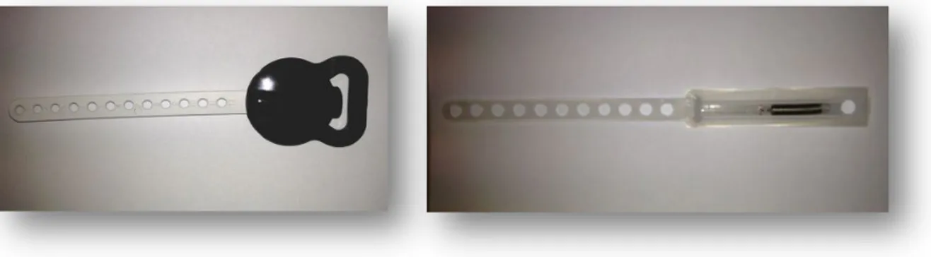
Figure 2 - Medium force module from Ormco® ... 7
Figure 3 - Medium force module from Ceosa® ... 7
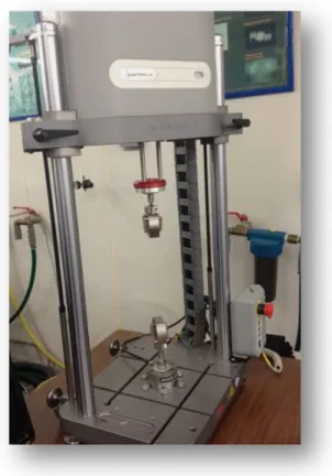
Figure 4 - Instron ElectrPuls E1000 machine ………. 8
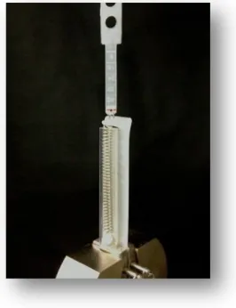
Figure 5 - Specimen from Ceosa® during tensile test ………. 9
Figure 6 - Specimen C4 during shot-term fatigue test ……… 10
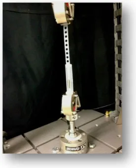
Figure 7 - Customized support structure for the constant load tension test …… 11
Figure 8 - Specimens C5, C6, O5 and O6 with calibrated masses ……….. 11
Table I - Description of the evaluated coil springs ……….. 7 Table II - Rigidity of the samples ………. 14
! $!
Graphics Index
!
Graph 1 - Tensile test – specimen O1 ... 12
Graph 2 – Tensile test – specimen C1 ... 13
Graph 3 - Trednline of the linear region of specimen O1 ... 13
Graph 4 - Trendline of the linear region of specimen C1 ... 14
Graph 5 - Group O’s load-displacement graph ... 15
Graph 6 - Group C’s load-displacement graph ... 15
Graph 7 - Load-time graph for specimen O4 ... 16
Graph 8 - Strain-time graph for specimen O4 ... 16
Graph 9 - Load-time graph for specimen C4 ... 17
Graph 10 - Strain-time graph for specimen C4 ... 17 !
1. Resumo
Introdução:!A ancoragem extra-oral continua a ser uma técnica muito utilizada no tratamento de diversas más-oclusões, principalmente em pacientes em fase de crescimento. Constitui um método muito útil de obter ancoragem numa variedade de tratamentos, podendo ser utilizado com fins ortodônticos e ortopédicos. De modo a cumprir os objetivos terapêuticos preconizados, é importante o médico dentista ter em consideração a qualidade destes dispositivos, tendo em conta o vasto leque de opções disponíveis no mercado. Assim, torna-se relevante perceber as características e o comportamento biomecânico dos constituintes destes aparelhos e a degradação dos seus componentes devido à perda de memória elástica e fadiga do material. O objetivo deste trabalho de investigação foi comparar sistemas de forças extraorais através do estudo das características das respectivas molas de tração e o seu revestimento. A avaliação destes dados poderá justificar a escolha entre estas duas opções testadas.
Materiais e Métodos: Neste estudo comparativo in vitro, um total de 12 módulos de tracção extraoral foram submetidos a testes de tração e fadiga curta. As amostras foram divididas em 2 grupos, de acordo com as marcas correspondentes.
Resultados: O comportamento mecânico dos módulos comparados era idêntico;! "#$"#! %&'"#"($%)%*! +*%! ',-,."/! #"*"01%($"2! 34($+.4! %#! *40%#! .%! 5'*34®! "'%*! 0,-",'%*"($"!
*%,#!'6-,.%#7!5#!$"#$"#!."!8%.,-%!3+'$%!*4#$'%'%*!9+"!(:4!14+)"!."84'*%;:4!%3+*+0%.%! (%#!%*4#$'%#2!&%'%!4!(<*"'4!."!3,304#!%&0,3%.4#=!"#$"#!'"#+0$%.4#!(:4!84'%*!34(30+#,)4#2!>?! 9+"! #"',%! ("3"##?',4! +*! (<*"'4! *%,#! "0")%.4! ."! 3,304#! &%'%! #"! &4."'! %(%0,#%'! %! ."84'*%;:4! #48',.%! &"0%#! %*4#$'%#7 O teste de tração a carga constante demonstrou que os módulos de força eram capazes de aplicar cargas constantes, mesmo durante um período de tempo superior ao número normal de horas de uso do aparelho.
Conclusões: Com tantos fatores a influenciar o tratamento com aparelhos extraorais, é importante saber que os dispositivos utilizados têm um comportamento mecânico confiável e que garante a aplicação de forças perfeitamente conhecidas, de forma segura e previsível.
Palavras-chave:
Aparelho ortodôntico extraoral, biomecânica orofacial, módulos de força extraoral, apoio craniano, mola de tração.Comparative Study of the Biomechanical Behaviour of Extraoral Force Modules
! !!
2. Abstract
"#$%&'()$*&#+! Extraoral traction is still one of the most reliable methods used during active orthodontic period in growing and non-growing patients. It is a very cost-effective method for attaining extra anchorage in a variety of treatment situations and it can be used either with orthodontic or orthopaedic purposes.!It is imperative for the clinician to consider the quality of the force systems, taking into account the degradation of its components, due to loss of elastic memory and material fatigue.!@1+#2!it is utterly important to understand the characteristics and mechanical behaviour of the extraoral device elements7!This investigation intended to compare extraoral force delivery systems through the study of coil spring components and its enclosure.! The assessment of this data may validate the choice criteria between these two market options. Materials and Methods: In this in vitro study, a total of 12 extraoral modules were submitted to tensile and short-term fatigue tests. The specimens were equally divided into two groups according to their manufacturers.
,-.(/$.+! @1"! *"31%(,3%0! A"1%),4+'! 48! $1"! 84'3"! *4.+0"#! 34*&%'".! B%#! ,."($,3%0=! $1"C! &'"#"($".!%!#,*,0%'!',-,.,$C2!")"(!$14+-1!5'*34®’#!*4.+0"#!B"'"!#0,-1$0C!*4'"!',-,.7!
The short-term fatigue tests showed that there was not any accumulated strain in any of the modules tested, for the number of cycles applied; these results were not conclusive, since it would be necessary to perform a superior number of cycles to obtain assessable results of the strain endured by the samples. The results from the constant load tension test showed that the modules applied a constant force, even for a longer period of time than the usual hours of use of the extraoral appliance.
Conclusions: With so many distinct factors influencing the treatment with extraoral force, it is important to know that at least the extraoral appliances have a reliable mechanical behaviour that ensures the application of perfectly known forces, in a safe and predictable way.
Key Words:
Orthodontic extraoral appliance, orofacial biomechanics, extraoral force modules, headgear, coil springs.3. Introduction
Orthodontics is a very versatile and controversial therapeutic area with diverse and distinct methodologies and numerous orthodontic appliances available in the market. The enormous amount of options allows the clinician to select the technique he believes to be the most beneficial for each patient. However, the selected option should always be focused on aims that may allow stable and lasting results, avoiding relapse.
The extraoral anchorage and traction are still one of the most reliable and recommended methods used during active orthodontic period in growing and non-growing patients. It is a very practical and cost-effective method for attaining extra anchorage in a variety of clinical situations and it can be used either with orthodontic or orthopaedic purposes. [2-4] According to some authors, extraoral devices are crucial components of a clinician’s armamentarium, not only to achieve predictable changes on the dentomaxillary complex, but also to supress or enhance intraoral force systems and to provide a controlled mechanism to displace bone structures. [5-7]
Extraoral headgear traction has been used since the late 1880s and has become a routine method to correct maxillary protrusions (particularly skeletal Class II, division 1 malocclusions), by restricting the forward growth of the maxilla and/or distalizing the upper molars, while the mandible grows forward naturally. [1, 8-12]
It is still unclear whether all craniofacial sutures react in a comparable manner in response to a particular force and whether a dose-response relationship exists (and to what extent) between the forces applied and the biologic reaction in a suture. An accurate study of the biological response to a force system compels the identification of all the characteristics of the given force. But in in
vivo conditions it is unmanageable to control all force variables influencing the force system. [9]
Nonetheless, studies have shown that it is possible to modify the growth of the entire maxillary complex by the application of mechanical forces. The response of sutural tissues to these forces is affected not only by the duration and the direction of the force, but also by the morphology of the suture and the age of the patient. [4, 9, 13]
The intensity and direction of force conveyed by these appliances is provided by force-delivery systems, such as elastomeric chains, stainless steel or NiTi coil springs. The link between intraoral device and extraoral headgear, cap or mask is established by these modular systems (figure 1). There are different types of headgear, each one of them used with a different purpose: cervical, high-pull (occipital), combined, reverse pull and chin cup. The first three types of
Comparative Study of the Biomechanical Behaviour of Extraoral Force Modules
! !!
headgear are employed in the correction of different types of Class II malocclusions, while the last two are used in Class III correction. [14] Even though high-pull, cervical and combined headgears are used for the correction of Class II malocclusions, the direction of force influences tooth movement and skeletal growth in distinct ways. For instance, cervical traction, which produces a distal and downward force against the maxillary teeth and the maxilla, tends to inhibit maxillary growth with a clockwise inclination of the palatal plane and usually causes the extrusion of maxillary molars, backward rotation of the mandible and an increase in lower face height. The occipital traction, on the other hand, would be applicable to patients with strong vertical growth, since this type of traction, which places a distal and upward force on the maxilla, tends to hold the palatal plane steady. [1, 12, 15, 16]
The clinician may apply light, medium or heavy forces (from 150 to 1250 g) to the maxillofacial complex, with constant and predetermined magnitude, in a safe and predictable way, in order to attain adequate therapeutic results with minor side effects and relapse. [2, 3, 15] Lighter magnitudes of force (under 350 g) only produce orthodontic movement, whereas to achieve orthopaedic modifications, higher levels of force should be applied. Nonetheless, it seems that extremely heavy forces (greater than 1000 g total) are unnecessarily traumatic to the teeth and their supporting structures. [1]
Fig. 1 – High-pull and cervical headgears. [1]!
Clinicians may recommend a part-time or continuous wear of the headgear, varying from 8 to 14 hours a day. [15] Ideally the patient should put on the appliance early in the evening, when the concentration of the growth hormone in the bloodstream is higher, and wear it continuously until the next morning. [1] The cooperation and tolerance are more easily achieved when the patient is asleep and the hormonal conditions allow maximizing the effect. [17, 18] [5]
Despite its effectiveness, these force systems rely entirely on patient compliance, which is often challenging to maintain throughout treatment, not only for the patient age range, mainly children and adolescents, but also due to difficulty of use and aesthetic concerns. [8, 18, 19] Patient cooperation has a key role on all strategies of orthodontic treatment and it is particularly true in headgear wearing. In fact, laxity in following the instructions often results in a slower treatment progress, increased costs, compromised treatment outcomes and the necessity to resort to a less-preferred alternative technique. [8, 18, 20-22]
Therefore, since the late eighties, in order to reduce the need for compliance, many types of intraoral devices have been introduced, namely: repelling magnets, superelastic nickel-titanium wires, Jones Jig, the pendulum device, the intraoral bodily molar distalizer and a few others. [8, 23, 24] These devices are easier to use, more socially acceptable and the distalization is achieved in a shorter period of time, because the force is continuosly applied. However, they present some disadvantages such as the mesialization of the upper premolars, protrusion of the maxillary incisors with an increased overjet and anchorage loss. [24] In recent years, the introduction of implant anchorage systems using titanium miniscrews and miniplates, represents an important alternative, providing absolute anchorage and better control of mandibular rotation, in addition to being relatively comfortable and easily accepted by patients. [21, 25]
Another important disadvantage of the use of headgear is the potential risk for facial injuries, due to inadequate handling during fitting or removal of the appliance, or unintentional disengagement during sleep. Although the risks are small, the morbidity of the injuries is high, because of the inoculation of oral flora into the lesions. [26-28] So it is fundamental to choose headgears with proper safety mechanisms and to carefully warn patients about the risks of incorrect use of the device. [28, 29]
The safety mechanism consists in the release of the head- or neckstrap from the facebow if any sharp force surpassing the therapeutic level is applied to the system, in order to prevent catapult injuries. According to a few authors, the mechanism should have a short extension release point, high consistency and should snap-away when forces above the therapeutic level are applied. [26-28]
Comparative Study of the Biomechanical Behaviour of Extraoral Force Modules
! !!
In addition, it is imperative for the clinician to consider the quality of the force systems, taking into account the degradation of its components, due to loss of elastic memory and material fatigue. The resulting force decline may result in dental movement instead of the expected skeletal change. [14, 30] Thus, it is utterly important that the clinician trusts and understands the characteristics and mechanical behaviour of the extraoral device elements. This knowledge allows selecting the most reliable appliance and the recognition of its eventual replacement. Coil springs used in force delivery systems can be made of different materials, such as stainless steel, which is an alloy of iron and other elements with wide-ranging uses in the medical industry. This option is thought to provide a constant force, to retain more force over a given period of time and to be more resistant to moisture and temperature when compared to elastomeric chains. [5] In spite of the superior mechanical properties of this alloy and its likelihood to provide better clinical outcomes, stainless steel springs are still relatively expensive and the ratio cost/benefit among different brands remains unclear. In addition, the plastic covers of the force modules vary between brands and have different features, which are possibly related to the mechanical response of the force delivery systems.
This investigation intended to compare extraoral force delivery systems through the study of coil spring component and their cover. Two different manufacturers were selected to show and analyse the force-degradation patterns of the force delivery systems. The selective criteria of those two brands were based on their market price, one of them being significantly more expensive than the other. The assessment of this data may validate the choice criteria between these two market options.
4. Materials and Methods
!
This orthodontic study is the result of a combined research involving the Engineering and Dental Medicine Faculties of Oporto University. A total of 12 pieces of stainless steel coil springs were tested in this in vitro study. The specimens were equally divided into two groups, according to the manufacturer: group O – Ormco® (California, USA) and group C - Ceosa® (Madrid, Spain),
and ultimately divided into six subgroups, as presented in table I.
Table I. Description of the evaluated coil springs.
!"#$%&'()*% +),&'()*% -('."% /'012%3401)50.$)'"'6% 70$08(&)"%.(2"%
!" !#" $%&'()" " *+","-"./" !0$1!®" 2#+34545" !4" !6" !7" !+" !-" 1" " 1#" 18!9:®" 446;35#" 14" 16" 17" 1+" 1-" " "
!
Fig. 2 and 3 – Medium force modules from Ormco® and Ceosa®.
!
!
!
!
Comparative Study of the Biomechanical Behaviour of Extraoral Force Modules
! !!
4.1. Tensile Test
Tensile tests were conducted in an Instron ElectroPuls E1000 machine (fig.4) from LABIOMEP (Porto Biomechanics Laboratory, University of Porto), with a 2 kN load cell, in displacement control, up to specimens’ limit, break or unlocking. Three specimens from each brand were tested, at a displacement rate of 5mm/min. The tests were followed by digital image correlation. Each plot produced by the internal chart recorder was transferred to a spread sheet and the data represented graphically as force versus displacement of the extended spring. These graphs allow the evaluation of samples deformation, when increasingly higher forces are applied. So, it allows the measurement of the rigidity of the modules.
The test consisted on applying an uniaxial tensile force to the specimen, generated by extending the module at constant speed. The specimens were fixed by their edges in the fixation claws of the Instron test machine and then they were subjected to strain; a gradual load was applied and every force value corresponding to a different stretching of the material was registered; each sample was tested with an extension speed of 5mm/min. Regarding the samples from group C, the test ended when the coil spring disengaged from the plastic strap (fig. 5). Regarding the
Fig. 4 - Instron ElectroPuls E1000 machine.!
samples from group O, the test ended when the safety mechanism broke-away, due to the application of excessive force.
4.2. Short-term Fatigue Test
Since these are mechanical devices, their behaviour is deterministic. In fact, while some variability in the individual spring features is expected, that variation is very minor, once these devices are always subjected to a strict quality control. To assess the force delivery repeatability of force modules and to verify their capacity to maintain unchanged their mechanical characteristics, a short-term fatigue test was conducted (fig. 6). This simulates the repeated application of force on each module. In this case, the universal test machine was programmed to apply 5000 sinusoidal cycles to the edges of each specimen, with a frequency of 1Hz. Only one sample from each brand was tested, since the small variation anticipated for these characteristics does not justify the repetition of such a costly test on more samples.!
Fig. 5 – Specimen from Ceosa® during tensile test; view of the disengagement of the coil spring from the plastic strap.
!
Comparative Study of the Biomechanical Behaviour of Extraoral Force Modules
! !"!
4.3. Constant load tension test
In order to achieve the intended traction and anchorage effects, the force applied by the extraoral modules should be stable over time. Since module force depends on its deflexion, it is important that during its solicitation it remains constant and without dimensional changes. With this in mind, a tension test with constant load was performed during a period of time far superior to the usual number of hours of extraoral appliance use (8 to 14 hours a day). This test enables the appraisal of the resistance to fluency of both the metallic body of the spring and the polymer used in the strap where the device links to the outer arm of the facebow.
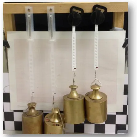
Accordingly, 4 modules (2 from each brand) were fixed in a support structure specifically created for this test (fig. 7). A constant load,obtained by the suspension of calibrated masses, was applied to each of the modules (fig. 8). They were subjected to a gravitational force of 9,8N, which is close to the maximum force of device use. The test lasted for 432 hours (18 days). In the beginning of the test, the initial position of the loaded modules was registered in a reference plane, using a millimetre paper. One mark was traced on each of the modules’ plastic straps and the four corresponding marks transferred to the millimetre paper. This way, any change in the initial position of the modules could be easily verified. The calibrated masses were suspended in order to apply the load to the total length of the module. The intention was subjecting all device components to strain.
Fig. 6 – View of specimen C4 from Ceosa® during the short-term fatigue test in the Instron machine.
!
Fig. 8 – View of specimens C5, C6, O5 and O6 with 9,8N calibrated masses in suspension.
!
!
Fig. 7 – Customized support structure for the constant load tension test.
!
Comparative Study of the Biomechanical Behaviour of Extraoral Force Modules
! !"!
5. Results
!
The mechanical devices studied in this investigation are normally produced in large scale by companies that specifically fabricate medical devices and materials. In order to commercialize this type of accessories, these companies must follow strict standards and regulations and also a rigorous quality control.
Since no variability in the mechanical characteristics of the devices is expected, statistical analysis of the attained experimental data is not justifiable in this investigation.
!
!
5.1. Tensile Tests
!
The test machine was adjusted to control the relative displacement between the two hooks and register the respective value, while the load was simultaneously applied to the specimen tested. The machine has a load cell and a displacement transductor, which send the data from the trial to the computer’s software.
! ! ! ! ! ! ! ! ! ! ! ! ! ! ! ! ! ! ! ! ! ! ! Graph 1 – Tensile test – specimen O1.
!
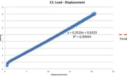
There is a linear region in the specimens test graph of both brands (graphs 1 and 2), which means that there is a directly proportional and linear relation between load and displacement; In group O, in the linear region of the load/displacement graph, the maximum load achieved was 9,5N, corresponding to a variation of 19,3mm of the total length of the specimen; in group C, the maximum load was 10,0N, corresponding to a variation of the total length of 25mm. Comparing the two specimens (O1 and C1), the reading of the linear regions supports a 5,3% higher maximum force for specimen C1.
The slope of the line in this part of the graphics represented the rigidity of the samples (in graphs 3 and 4). The trendlines of the other specimens tested (O2, O3, C2 and C3) are presented in Attachment 1.
Graph 2 – Tensile test – specimen C1.
!
!
Graph 3 – Trendline of the linear region of specimen O1.
!
Comparative Study of the Biomechanical Behaviour of Extraoral Force Modules
! !"!
Manufacturer Specimen Rigidity R2
Ormco® O1 0.3899 0,99957 O2 0,4221 0,95591 O3 0,3922 0,9996 CEOSA® C1 0.3526 0,99944 C2 0,3464 0,99963 C3 0,3671 0,99898
The rigidity of the samples presented was very similar, though group O’s samples presented slightly superior values, which means that for the same displacement, these modules can apply heavier forces than the modules from the other brand.
Graph 4 – Trendline of the linear region of specimen C1.
!
!
Table II – Rigidity of the samples.
!
All 3 tensile tests performed for each brand showed that the specimens from the same manufacturer behaved in a very similar way, as we can observe in graphs 5 and 6. From these graphs the medium maximum force of each brand can be determined: 9,2N for Ormco® and
10,4N for CEOSA®, corresponding respectively to total length variations of 19,1mm and of
25,0mm.
Graph 5 – Linear region of the load-displacement graphs of group O’s force modules.
!
!
Graph 6 – Linear region of the load-displacement graphs of group C’s force modules.
!
Comparative Study of the Biomechanical Behaviour of Extraoral Force Modules
! !"!
5.2. Short-term Fatigue Tests
!
In this trial 5000 load cycles were carried out, with the load varying sinusoidally between 0 and 4N for specimen O4 and between 0 and 2,5N for specimen C4 (graphs 7, 8, 9 and 10), taking into account its behaviour in the tensile tests. With only 5000 cycles it was not possible to take any conclusions about the accumulated deformation of the samples. Thus it should have been necessary to perform new tests with a superior number of cycles. In fatigue tests, it is better to have a higher number of cycles, hundred thousands or millions of cycles. This allows tracing a S-N curve, in which a relation between tension and number of cycles is determined.
! ! ! ! ! ! ! ! ! ! ! ! ! ! ! ! ! ! ! ! ! ! ! ! ! ! ! ! ! ! ! ! ! ! !
Graphs 7 and 8 – Load-Time and Strain-Time charts for specimen O4.
!
! ! !
Graph 9 and 10 – Load-Time and Strain-Time charts for specimen C4.
!
Comparative Study of the Biomechanical Behaviour of Extraoral Force Modules
! !"!
5.3. Constant load tension test
!
With an average 1mm error, we can say that there was no change in the position of the samples after 432 hours (fig. 9). It means that for this period of time, the force applied by the devices of both brands remained unaffected or, in other words, it is constant.
!
! ! ! ! ! ! ! ! ! ! ! ! ! ! ! ! ! ! ! ! ! ! ! ! ! ! ! ! ! ! ! ! ! ! ! ! ! !Fig. 9 – Photograph after 18 days (432hours) of constant load tension application. No change in the initial position of the marks occurred.
!
6. Discussion
! !
Extraoral force modules are devices designed to apply perfectly known forces, in direction and magnitude, in different clinical situations. Hence, the mechanical characteristics of these appliances and its maintenance over use time are of capital importance. In fact, it is not only important to know in detail the rigidity and the maximum and minimum forces delivered by these devices, but also how those values are sustained over time.
According to the results of the tests performed, the force modules from both brands had a similar mechanical behaviour. However, the tensile test showed that the Ormco® samples displayed a
slightly superior rigidity than the ones from Ceosa®. This means that for the same displacement,
group O’s modules could apply superior levels of force than group C’s. Nevertheless, it is unsafe to apply heavy forces to group C modules, since they do not have a safety mechanism, leading to an increased risk of high morbidity injuries to the patient. [26-29] Also, forces superior to 10N are likely to cause the detachment of the coil spring from the plastic strap, which makes the module unusable. Group O’s modules on the other hand, have a safety release mechanism, which snaps away if forces superior to 10N are applied. This way, the device remains functional after the uncoupling of its components, by the application of an inadequate magnitude of force. This detail may justify the price disparity between the two brands.
Regarding to the short-term fatigue tests, the results showed that there was no accumulated strain in any of the tested modules. However, these results were not conclusive, since the number of cycles applied was too small. D(!8+$+'"!#$+.,"#2!$1"!8%$,-+"!$"#$#!#14+0.!A"!04(-"'!%(.!1%)"! *4'"!3C30"#2!84'!$1"!#%*"!8'"9+"(3C=!4$1"'!8%$,-+"!$"#$#!34+0.!%0#4!1%)"!%!#+&"',4'!(+*A"'! 48! 3C30"#! %(.! %! 1,-1"'! 8'"9+"(3C! %#! B"002! B1,31! B4+0.! %004B! $4! '"%31! %! 1,-1! (+*A"'! 48! 3C30"#!*4'"!9+,3E0C=!$1"#"!$"#$#!B4+0.!&'4A%A0C!%004B!$4!4A$%,(!%##"##%A0"!.,88"'"(3"#!,(! $1"!%33+*+0%$".!#$'%,(!"(.+'".!AC!$1"!.,88"'"($!*4.+0"#7
The results from the constant load tension test showed that, with an average error of 1mm, there was no alteration in the initial position of the modules throughout the test. So, it means that for the load applied, the displacement of the modules is constant, even for a superior number of hours than the usual hours of use of the appliance. Nonetheless, if the test was carried out for a longer period of time, then maybe we could assess if there are any significant differences in the
Comparative Study of the Biomechanical Behaviour of Extraoral Force Modules
! !"!
deformation suffered by the different samples. In that case, those results would show that the modules produced by one manufacturer have better quality than the ones from the other brand. In fact, the use of these devices is usually prescribed for about 8 to 12 months, during on average 10 hours a day. In this trial the test lasted for 432 hours, corresponding to an use of a month and a half. F0$14+-1!$1"!*"31%(,3%0!A"1%),4+'!48!"G$'%4'%0!%&&0,%(3"#!*%C!A"!)"'C!#,*,0%'2!$1"!30,(,3%0! 4+$34*"#!4A#"')".!3%(!)%'C!9+,$"!%!04$=!,$H#!$1"!&%$,"($H#!,(.,),.+%0!31%'%3$"',#$,3#!B1,31! B,00! .,3$%$"! $1"! '"#+0$#! 48! $1"! $'"%$*"($2! #,(3"! #+$+'%0! '"#&4(#"! $4! *"31%(,3%0! 84'3"#! ,#! "G&"3$".!$4!)%'C!8'4*!&%$,"($!$4!&%$,"($=!*4'"4)"'2!&%$,"($!34*&0,%(3"!&0%C#!%!3',$,3%0!'40"! ,(!$'"%$*"($!#+33"##7!IJ2!K2!LK2!JJM!N,$1!#4!*%(C!.,#$,(3$!8%3$4'#!,(80+"(3,(-!$1"!$'"%$*"($! B,$1!"G$'%4'%0!84'3"2!O&%$,"($!%-"2!,(.,),.+%0!)%',%A,0,$C2!34*&0,%(3"2!.,'"3$,4(!%(.!,($"(#,$C! 48! 84'3"! %&&0,".PQ! ,$! ,#! ,*&4'$%($! $4! E(4B! $1%$! %$! 0"%#$! $1"! ."),3"#! +#".! 84'! $1,#! $C&"! 48! $'"%$*"($! 1%)"! %! '"0,%A0"! *"31%(,3%0! A"1%),4+'! $1%$! "(#+'"#! $1"! %&&0,3%$,4(! 48! &"'8"3$0C! E(4B(!84'3"#2!,(!%!#%8"!%(.!&'".,3$%A0"!B%C7!
7. Conclusions
!
Under the conditions of this comparative in vitro study of extraoral force modules from 2 different manufacturers, the following conclusions were reached:
1. The mechanical behaviour of the extraoral force modules compared was identical; they presented a very similar rigidity, even though Ormco®’s modules were slightly more rigid.
2. These mechanical devices have a well-known and predictable performance, since they are fabricated under strict regulations and control; small differences in the mechanical behaviour of the coil springs between brands are expected; the major differences might be found in the polymer used in the cover of the modules, but this aspect needs posterior detailed assessment.
3. The price discrepancy may be well justified by the safety mechanism presented by one of the brands, which greatly reduces the risk of serious injuries to the patient.
4. The tests performed allow to conclude that the behaviour of these appliances is predictable, so these are trustable devices.
Comparative Study of the Biomechanical Behaviour of Extraoral Force Modules
! !!!
8. References
!
!
1. Proffit WR, Fields HW, Sarver DM: Comtemporary Orthodontics, Fourth Edition, 4th edn: Mosby; 2007.
2. Braun S: Extraoral appliances: A twenty-first century update. AJO-DO 2004, 125(5):624-629.
3. Yamada L: Aparelhos extra-bucais no tratamento de maloclusões de Classe II.
Monografia. Instituto de Pesquisa e Ensino de Cruzeiro (IEP); 2008.
4. Samuels RH, DiBiase AT: Changes in circumferential neck measurements during movements of the head in children and their relevance to extraoral traction. Angle
Orthod 2001, 71(1):44-49.
5. von Fraunhofer JA, Bonds PW, Johnson BE: Force generation by orthodontic coil springs. Angle Orthod 1993, 63(2):145-148.
6. Verrue V, Dermaut L, Verhegghe B: Three-dimensional finite element modelling of a dog skull for the simulation of initial orthopaedic displacements. Eur J Orthod 2001, 23(5):517-527.
7. Billiet T, de Pauw G, Dermaut L: Location of the centre of resistance of the upper dentition and the nasomaxillary complex. An experimental study. Eur J Orthod 2001, 23(3):263-273.
8. Kaya B, Arman A, Uckan S, Yazici AC: Comparison of the zygoma anchorage system with cervical headgear in buccal segment distalization. Eur J Orthod 2009, 31(4):417-424.
9. Wagemans PA, van de Velde JP, Kuijpers-Jagtman AM: Sutures and forces: a review.
AJO-DO 1988, 94(2):129-141.
10. Katada H, Katada H, Isshiki Y: Changes in orthodontic cephalometric reference points on application of orthopedic force to jaw: three-dimensional finite element analysis. The Bulletin of Tokyo Dental College 2005, 46(3):59-65.
11. Kirjavainen M, Kirjavainen T, Haavikko K: Changes in dental arch dimensions by use of an orthopedic cervical headgear in Class II correction. American journal of
orthodontics and dentofacial orthopedics : official publication of the American Association of Orthodontists, its constituent societies, and the American Board of Orthodontics 1997, 111(1):59-66.
12. Alio-Sanz J, Iglesias-Conde C, Lorenzo-Pernia J, Iglesias-Linares A, Mendoza-Mendoza A, Solano-Reina E: Effects on the maxilla and cranial base caused by cervical headgear: a longitudinal study. Medicina oral, patologia oral y cirugia bucal 2012, 17(5):e845-851.
13. Mao JJ, Wang X, Kopher RA: Biomechanics of craniofacial sutures: orthopedic implications. Angle Orthod 2003, 73(2):128-135.
14. Headgear Appliances - Natalie A. Capan, D.M.D.
[1$$&RSSBBB7340+*A,%7".+S,$3S1#S."($%0STUVWWSX"%.-"%'! F&&0,%(3"#! Y! Z40+*A,%! ["B\]N7&.8]
15. Ricketts RM: A statement regarding early treatment. AJO-DO 2000, 117(5):556-558. 16. Howard RD: Skeletal changes with extra oral traction. Eur J Orthod 1982,
4(3):197-202.
17. Leonardi R, Lombardo C, Loreto C, Caltabiano R: Pressure alopecia from orthodontic headgear. AJO-DO 2008, 134(3):456-458.
18. Brandao M, Pinho HS, Urias D: Clinical and quantitative assessment of headgear compliance: a pilot study. AJO-DO 2006, 129(2):239-244.
19. Doruk C, Agar U, Babacan H: The role of the headgear timer in extraoral co-operation. Eur J Orthod 2004, 26(3):289-291.
20. Altug-Atac AT, Erdem D: Effects of three-dimensional bimetric maxillary distalizing arches and cervical headgear on dentofacial structures. Eur J Orthod 2007, 29(1):52-59.
21. Koyama I, Iino S, Abe Y, Takano-Yamamoto T, Miyawaki S: Differences between sliding mechanics with implant anchorage and straight-pull headgear and intermaxillary elastics in adults with bimaxillary protrusion. Eur J Orthod 2011, 33(2):126-131.
22. Bos A, Kleverlaan CJ, Hoogstraten J, Prahl-Andersen B, Kuitert R: Comparing subjective and objective measures of headgear compliance. AJO-DO 2007, 132(6):801-805.
23. Haydar S, Uner O: Comparison of Jones jig molar distalization appliance with extraoral traction. AJO-DO 2000, 117(1):49-53.
24. Acar AG, Gursoy S, Dincer M: Molar distalization with a pendulum appliance K-loop combination. Eur J Orthod 2010, 32(4):459-465.
Comparative Study of the Biomechanical Behaviour of Extraoral Force Modules
! !"!
25. Ma J, Wang L, Zhang W, Chen W, Zhao C, Smales RJ: Comparative evaluation of micro-implant and headgear anchorage used with a pre-adjusted appliance system.
Eur J Orthod 2008, 30(3):283-287.
26. Samuels RH: A review of orthodontic face-bow injuries and safety equipment.
AJO-DO 1996, 110(3):269-272.
27. Stafford GD, Caputo AA, Turley PK: Characteristics of headgear release mechanisms: safety implications. Angle Orthod 1998, 68(4):319-326.
28. Booth-Mason S, Birnie D: Penetrating eye injury from orthodontic headgear--a case report. Eur J Orthod 1988, 10(2):111-114.
29. Postlethwaite K: The range and effectiveness of safety headgear products. Eur J
Orthod 1989, 11(3):228-234.
30. Mirhashemi A, Saffarshahroudi A, Sodagar A, Atai M: Force-degradation pattern of six different orthodontic elastomeric chains. Journal of dentistry (Tehran, Iran) 2012, 9(4):204-215.
!
!
!
!
!
!
!
!
ATTACHMENTS
!
!
!
!
!
!
!
Comparative Study of the Biomechanical Behaviour of Extraoral Force Modules ! !"!
ATTACHMENT 1 - Graphics
! ! ! ! ! ! ! ! ! ! ! ! !ORMCO® ! ! ! ! ! ! ! ! ! ! ! ! ! ! ! ! ! ! ! ! ! ! ! ! ! ! ! ! ! ! ! ! ! ! ! ! ! ! ! ! ! !
Comparative Study of the Biomechanical Behaviour of Extraoral Force Modules ! !"! ! ! ! ! ! ! ! ! ! ! ! ! ! ! ! ! ! ! ! ! ! ! ! ! ! ! ! ! ! ! ! ! ! !
CEOSA
® ! ! ! ! ! ! ! ! ! ! ! ! ! ! ! ! ! ! ! ! ! ! ! ! ! ! ! ! ! ! ! ! ! ! ! ! ! ! ! ! ! ! ! ! ! !Comparative Study of the Biomechanical Behaviour of Extraoral Force Modules ! !"! ! ! ! ! ! ! ! ! ! ! ! ! ! ! ! ! ! ! ! ! ! ! ! !
!
ATTACHMENT 2
!!
![Fig. 1 – High-pull and cervical headgears. [1]!](https://thumb-eu.123doks.com/thumbv2/123dok_br/15212124.1019504/14.892.191.781.486.858/fig-high-pull-and-cervical-headgears.webp)