Wireless Power Transfer Impact on Data Channel
Elena N. Baikova, Stanimir S. Valtchev
UNINOVA-CTS, Faculdade de Ciências e Tecnologia,Universidade Nova de Lisboa, Portugal; EST, Instituto Politécnico de Setúbal, Portugal
R. Melício, V. Fernão Pires
IDMEC, Instituto Superior Técnico, Universidade de Lisboa; Departamento de Física, Escola de Ciências e Tecnologia, Universidade de Évora, Portugal; INESC-ID Lisboa, EST, Instituto Politécnico de Setúbal, Portugal
Abstract—This paper presents measurement results and analysis of the interference produced by the high-power electromagnetic field in a wireless energy transfer system. Through this analysis it is expected to be possible to evaluate the influence of the strong electromagnetic field on the data transmission channel. The wireless power transfer aimed at electric vehicles battery charging receives a great deal of attention in the recent years. However, the performance of those systems depends on the exchange of information between the transmitter and the receiver, e.g. vehicle identification, frequency, required power, payment information. Thus, it is essential to ensure that the electromagnetic interference, generated by the wireless power transfer system will not influence or disrupt the communication between the transmitter and the receiver.
Keywords—Wireless power and data transmission; electromagnetic field; electromagnetic interference; impact on data channel
I. INTRODUCTION
The Wireless Power Transfer with its abbreviation WPT, was introduced widely the early 1990s and today it is one of the most attractive new technologies for researchers and manufacturers [1]. The WPT technology is capable to find solutions for problems that are impossible to solve in a classical way and to be widely applied in the real world equipment. In the future, the WPT technology could be even a competitor to the wired high voltage transmission line [2,3].
In the area of low power, advances in the power transfer allowed the use of electronic devices, e.g. mobile phones, laptops, wireless headphones, implants or razors. In the same time, the high power equipment manufacturers are willing to get free from the wires too. The intelligent machining systems, robots, the forklift trucks, and electric/hybrid cars are starting to become wireless [1]. Recently, a great deal of attention has been focused on the wireless charging systems for electric vehicles (EV) [1].
Among the existent WPT technologies one of the best results was obtained by Kurs et al. using magnetically coupled resonators [4]. The magnetic resonance technology is proven to be the most suitable to achieve efficient energy transfer for the EV wireless charging [4-6]. The resonant magnetic coupling system is more advantageous since it does not need an accurate parking position of the vehicle as in the case of inductive coupling [1].
The communications play a key role in the wireless charging systems. The data transmission during WPT allows a transmitter unit to detect and identify receivers and optimize the energy transfer process by increasing or decreasing the transferred power [1]. Different methods have been used by several authors for the simultaneous transmission of power and data in the WPT systems, aimed at increasing their efficiency and reliability. The simultaneous power and data exchange needs a proper choice of the modulation strategy and some ideas are proposed in the inductive powering systems [7,8] and in the resonant systems [9,10].
The wireless power and data transmission system with resonant coils tuned at one single working frequency is analyzed in [7-9]. The transmitted working frequency is modulated at the same time by the data transmission and the receiver may also modulate its rectifier switches in order to respond. In order not to be influenced by the energy transfer the data transmission can be treated by different technical methods, as amplitude shift keying (ASK), phase shift keying (PSK) [7-9] and frequency shift keying (FSK) modulation [11].
The feasibility of the joined power and the data receiver implementation with the application of amplitude modulation with a single antenna is proposed in [7]. The system of wireless power and data transmission described in [9] operates at a frequency of 13.56 MHz and allows a simultaneous transmission of energy and data, while the data goes at a speed up to 1 Mb/s. The operation principle is the modulation of the carrier frequency by the information signal.
An example of a compact energy and data transmission device is shown in [12]. This is a three-coil construction where the inner coil is a receiver of energy and data, and the inductive transmitter has two coils: one is the “energy” coil and the other is the “external receiver” coil. That external receiver receives the signal from the modulations of the load (as mentioned above, the modulations of the consumption are sensed as a signal from the receiver to the transmitter).
interference by the voltage induced electromagnetically by the WPT system can be reduced [14].
Some proposed solutions, like shifting the switching frequency [15-17] between the data and the power transfer channel, seem difficult to implement because of the compulsory synchronization, especially in a very dynamic environment.
Every one of the described systems has disadvantages. The data transmission rate and the transferred energy are limited. Furthermore, the construction of the resonant coil should ensure a sufficient isolation between the power and the data transmission systems, which is difficult to accomplish. These difficulties can be avoided if the data exchange is executed at much higher frequencies, particularly in the GHz order, keeping low frequency for the energy transfer [18]. The used high frequency allows for increasing the data rate and reducing the electromagnetic interferences, generated by power transfer system. The higher frequency of data transmission guaranties a higher bit rate and a better WPT harmonics filtering.
An example of a WPT system for charging the EV battery and for simultaneously transferring data is shown in [10]. To optimize the charging condition a bidirectional communication between the transmitter and the receiver, a communication block with two 2.4 GHz ZigBee units, is proposed.
This paper presents an application of wireless communications technologies in high power WPT, focusing on the electromagnetic compatibility (EMC) problems in simultaneous wireless energy and data transfer system. As far as it is known, a wide overview of the EMC problems of wireless power transfer simultaneously with the wireless data transmission has not yet been reported [19]. Thus, this paper is the contribution in the field of EMC issues of the wireless power e data transmission systems.
The rest of the paper is organized as followed: Section II presents the wireless data technology for the WPT system. Section III presents the wireless data transmission and the wireless data transmission modelling and the efficiency of the WPT system. Section IV presents the experimental part. Section V presents concluding remarks.
II. WIRELESS DATA TECHNOLOGY FOR WPTSYSTEM A data transmission system by higher carrier frequency (on the order of GHz) allows increasing the data transmission rate. In the area of the information transmission systems, the technologies that are most convenient to be adopted for WPT are, for example: Bluetooth, Wi-Fi, ZigBee [1,10,20,21].
The research and development that chooses well known and well supported technology, allows for obtaining more reliable solutions. As a consequence, one important factor for the wireless data technology will be the high level of standardization and interoperability between devices from different manufacturers. According to [21], in general, there are five potential wireless networks that are capable to be considered for intra- and inter-vehicles applications, namely
Bluetooth, UWB, RFID, ZigBee and Wi-Fi. However, only the Bluetooth was really implemented in several vehicle models in the recent years and it is getting now widely used technology [21,22]. The data technologies ZigBee, UWB and Wi-Fi have not yet been implemented in vehicles, and investigations in this field are still in development [21]. The ZigBee fills a gap provided by the other technologies, serving as a wireless sensor interconnection for the control purpose. It is expected that the ZigBee can be used in monitoring and control applications, related to temperature and moisture measurement, as well as heating, air conditioning and lighting control [22]. Having into account that well-known, developed and supported technologies already exist, it is easier to use the most widely spread technology in WPT systems. In this way of thinking the important factor for choosing the wireless data transmission technology is the high level of standardization and interoperability between devices from different manufacturers [22].
Given these considerations and the fact that Bluetooth technology is the most widely used in the automotive industry [21,22], it is considered a good balance between the data rate, the efficiency, and the cost. According to these considerations, this technology (Bluetooth) was chosen as suitable for data transmission inside the WPT system.
III. MODELLING
Currently, in the Power Electronics Laboratory of the Faculty of Science and Technology (FCT) / University Nova of Lisbon, the wireless power transfer and the data transmission system are experimented. The construction is based on the magnetic resonant coupling.
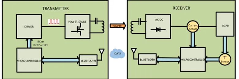
The simultaneous wireless powering and data communication transmitter and receiver block diagram is shown in Fig. 1.
DRIVER
POW ER STAGE
I2C or R232 or SP I
AC-DC
LO AD
BL UETOOTH
Current Sensor
tᵒ
Sensor MICRO CONTR OLL ER Com mun ication
POW ER
BL UETOOTH
TRANSMITTER RECEIVER
DATA
MICRO CONTR OLL ER
Fig. 1. Simultaneous wireless powering and data communication system.
The transmitter consists of a driver, a power stage, a transmitting coil and a microcontroller. The receiver side includes a receiving coil, a rectifier, a microcontroller with current and temperature sensors respectively. The load is the EV battery or a digital load that substitutes the battery. For the coordination between the transmitter and the receiver and for the optimization of the WPT system operation, a new set of microcontrollers is in development.
parallel-series (PS) and parallel-parallel (PP) [1,23,24]. If a parallel compensation PP is used at either side, the capacitance value depends on the coupling coefficient, which varies a lot when the load is moving. Therefore, the SS compensation is preferred for the EV applications [24] and was chosen for the proposed WPT system.
The schematic representation of a WPT system is shown in Fig. 2. It consists of two coils, where V is the HF AC power S source, RSis the internal resistance of the power source,
1
R ,L and1 C are respectively the primary parasitic resistor, 1 inductance and resonant capacitor,
M
12 is the mutual inductance between the primary and the secondary. The elements R ,2 L and2 C2are correspondingly the secondary parasitic resistor, the inductance and the resonant capacitor, and RL is the load resistance.RL
RS
C1 R1
L1 L2
R2 C2
M12
Primary coil Secondary coil
i2
VS
i1
Fig. 2. Schematic representation of a WPT system.
The equivalent circuit of the WPT system is shown in Fig. 3.
RS
RL
C1 L1 L2 C2
VS
M12
R1 R2
Fig. 3. Equivalent circuit of the WPT system.
The two coils are connected together via a magnetic field, characterized by coupling coefficient k12, given by:
2 1 12 12 L L M
k
The Kirchhoff’s voltage law for the primary is given by:
s i j M i vS
C j L j R
R 1 12 2
1 1 1 ) 1 (
The Kirchhoff’s voltage law for the secondary is given by:
( 1 )2 121 0
2 2
2
i j M i
C j L j R
RL
The loop impedances for the two coils is given by:
12 12 12 12 1 C j L j R R
Z SL
The currents of primary and secondary are given by:
2 12 2 2 1 2 1 M Z Z v Z I S 2 12 2 2 1 12 2 M Z Z v M j I S
At the resonance, the reactive part of the impedance of the coils becomes zero. Therefore, at the resonant frequency the currents I1 and I2 can be simplified given by:
2 12 2 2 1 2 1 ' ' ' M R R V R I S 2 12 2 2 1 12 2 '
'R M
R V M j I S
where R1'andR2' respectively, are the total transmitting and receiving circuit resistances, is given by:
R1'RSR1
R2'R2RL
The power of the input side Pin and output power delivered to the load Pout is given by:
PinVSI1cos
2
212 2 2 1 2 2 12 2 2 2 '
'R M
R V M R I R
Pout L L S
The power transfer efficiency is given by:
cos ) ' ' (
' 1 2 2 122
2 2 12 2 M R R R M R P P L in out
In (13), the power transfer efficiency is a function of the frequency and the circuit parameters. The efficiency decreases quickly when slides away from its resonant operation. A supposed high quality factor Q can increase the efficiency of the WPT system operating at resonance frequency.
For a series resonance the quality factor Q is given by:
RL
C L
R
IV. EXPERIMENTAL PART
The Electromagnetic Interference (EMI) is important especially for the digital and analogue systems operating at 30 MHz to 300 MHz frequencies, where any circuit element becomes an antenna and can cause interference. The analysis was concentrated on the EM radiation caused by the converter operating at 20 kHz switching frequency, at which frequency the most powerful WPT systems normally operate. In principle, the EMI from a relatively low switching frequency, as this one, will not provoke problems. The Bluetooth technology operates at the frequency of 2.4 GHz which is expected to be enough far from the highest order harmonics of the power transfer frequency (20 kHz). In the same time there is a risk of interference caused by the transmitters as the power will be very high (many kW) and haphazard modulation on the power transfer frequency is possible, e.g. by the movement of the transmitting and receiving equipment (EVs).
In order to verify this hypothetical influence, some initial measurements and analysis were done.
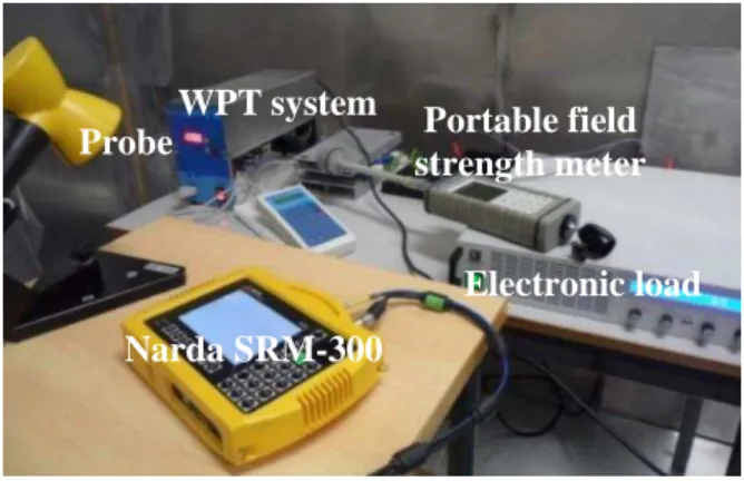
The test equipment used to perform measurements was composed by an experimental WPT system and a specialized measurement equipment. The WPT system consists of an adapted high frequency power generator, originally produced at the enterprise APRONECS Ltd., Bulgaria. This generator was connected to a transmitting coil included in a resonant circuit, and the receiver has another coil in a rectifier resonant circuit. The rectifier is loaded by an electronic programmable load. The EMI measurement equipment consist of a measuring instrument Narda SRM-3000 (Selective Radiation Meter), a portable electromagnetic field strength meter PMM 8053A, and various antennas in 100 kHz ÷ 3 GHz frequency domain.
The first series of electromagnetic (electric) field intensity measurements in the WPT system, taken in the Power Electronics Laboratory of the Department of Electrical Engineering (DEE) of the Faculty of Science and Technologies (FCT) of the University NOVA of Lisbon, is shown in Fig. 4.
Fig. 4. Electric field intensity in WPT system.
Fig. 4 shows some disturbance at the frequency 1.9 MHz
which may be caused by the intensive operation of the nearby located smartphone. Because of this, and in order to prevent external electromagnetic interference, the second series of measurements was made inside a Faraday cage. The experimental setup of the WPT system and the measuring equipment in the Faraday cage are shown in Fig. 5.
Fig. 5. WPT system: experimental setup.
The first measurement cycle of the second series was executed when the WPT system was switched off. The results of electric field intensity are shown in Fig. 6.
Fig. 6 shows interferences at frequencies between 100 kHz and 200 kHz. This can be explained by the nearby fluorescent lamp, whose electronic ballast was operating in that range of frequencies.
Fig. 6. Electric field in the absence of interference of the WPT system.
The harmonics generation from the WPT system, operating at 20 kHz frequency is shown in Fig. 7. The used measurement equipment was capable to analyze frequencies starting from 100 kHz, so the amplitudes of the harmonics were measured starting from the 5th harmonic ((100 kHz).
To obtain the 1st harmonic and the 3rd harmonic amplitudes, the minimum squares method of approximation was used. By this calculation, the experimental data were equilibrated by a coefficient of determination R20.9685.
Electronic load
Narda SRM-300
Probe
Portable field
Fig. 7. WPT system: harmonic generation at 20 kHz frequency
The high value obtained for R2, indicates that the trendline quite precisely fits the data. The amplitudes of the harmonics including the 1st harmonic and the 3rd one, generated by the WPT system are shown in Fig. 8.
Fig. 8. Amplitudes of the harmonics generated by WPT system.
Fig. 9. Electric Field amplitude at the distance from the WPT system.
The practical values of the electric field E in function of the distance from the WPT system are shown in Fig. 9. Fig. 9 demonstrates that the electric (electromagnetic, in general) field is much stronger close to the WPT system but it falls
down rapidly with the distance from the windings.The aim of these measurements is to evaluate the electromagnetic field level generated by the WPT systems.
In order to estimate the electromagnetic interference impact on data wireless channel, it was necessary to evaluate the bit error rate (BER), the packet error rate (PER), or throughput of the communication system.
The most usual method to evaluate receiving quality of data wireless channel, including the effect of interference and disturbance in industrial wireless communication, is to check the PER. The PER is the percentage of the number of packets that failed to be received correctly to the number of whole packets transmitted. The PER is also one of the factors determining system throughput and latency [25].
The Bluetooth communication performance was evaluated using the free software Iperf3 and Wireshark. Initially Bluetooth communication between two laptops placed in the operating area of WPT system. One of the laptops was used as a server and the other one was a client. The client created data streams and transferred them to the server via Bluetooth, applying the software Iperf3. The server created data streams and sent them back to the client using the software Iperf3.
A network protocol analyzer Wireshark was used installed on the server to capture frames and to determine the PER. It is capable to capture and analyze packets and to determine those ones that were lost by transmission errors [26].
The Wireshark capture file is shown in Fig. 10.
Fig. 10. Wireshark Capture file.
The results confirmed that there were no packets with transmission errors, so it can be considered that the studied WPT system does not influence the data wireless channel operating at 2.4 GHz frequency in the case of Bluetooth applied as data channel [27,28].
V. CONCLUSIONS
wireless data technology was also presented. From the described technologies, the Bluetooth can be considered one of the solid candidates for the data transmission in Wireless Power Transfer systems. To prevent external electromagnetic interference, the measurements of the electromagnetic fields generated by Wireless Power Transfer system were taken in the Faraday cage. The intensity of the electromagnetic field, due to the Wireless Power Transfer, was strong. In order to estimate the possible impact of the electromagnetic interference on the wireless data transfer channel, the evaluation of the packet error rate was made. The results of the experiments confirmed that there is no significant impact from the Wireless Power Transfer system operating at 20 kHz frequency on the data transfer channel, operating at 2.4 GHz frequency. In the future, a higher level of transferred power will be experimented.
ACKNOWLEDGMENT
The authors express their gratitude for the friendly help obtained from the colleagues of INESC INOVE, Lisbon, and their help made possible the measurements. The presentation of the work is partly funded by CTS/UNINOVA, Faculty of Science and Technology (FCT), University Nova de Lisboa. The laboratory and the Faraday Cage are also made available by the FCT faculty. Gratitude is expressed to some other institutions, presented by their members: IDMEC, Instituto Superior Técnico, Universidade de Lisboa and the EST of the Polytechnic Institute of Setubal.
REFERENCES
[1] S. Li, and C. Mi, “Wireless power transfer for electric vehicle applications,” IEEE Journal of Emerging and Selected Topics in Power Electronics, vol. 3(1), pp. 4–17, 2015.
[2] A. Kurs, A. Karalis, R. Moffatt, J.D. Joannopoulos, P. Fisher, and M.
Soljaćić, “Wireless power transfer via strongly coupled magnetic resonances,” Science Express, vol. 317, pp. 83–86, 2007.
[3] T. Imura, H. Okabe, and Y. Hori, “Basic experimental study on helical antennas of wireless power transfer for electric vehicles by using magnetic resonant couplings,” Proc. IEEE Vehicle Power and Propulsion Conference, p. 936–940, Dearborn, USA, 7-10 September 2009.
[4] C. Zhu, K. Liu, C. Yu, M. Rui, and H. Cheng, “Simulation and experimental analysis on wireless energy transfer based on magnetic resonances,” Proc. IEEE Vehicle Power and Propulsion Conference, p. 1–4, Harbin, China, 3-5 September 2008.
[5] C-T.M. Wu, J.S. Sun, and T. Itoh, “A simple self-powered AM-demodulator for wireless/data transmission,” Proc. 42th European Microwave Conference, p. 325–328, Amsterdam, Holland, 29-1 October-November 2012.
[6] G.V. Tibajia, and M.C. Talampas, “Development and evaluation of simultaneous wireless transmission of power and data for oceanographic
devices,” Proc. IEEE Sensors, p. 254–257, Limerick, Ireland, 28-31 October 2011.
[7] G.B. Hmida, H. Ghairani, and M. Samet, “Design of a wireless power and data transmission circuits for implantable biomicrosystem,” Biotechnology, vol. 6(2), pp. 153–164, 2007.
[8] Y. Yokoi, A. Taniya, M. Horiuchi, and S. Kobayashi, “Development of kW class wireless power transmission system for EV using magnetic
resonant method,” Proc. 1st International Electric Vehicle Technology Conference, p. 1-6, Yokohama, Japan, 17–19 May 2011.
[9] Y. Huang, C. Fang, and X. Li, “Contactless power and data transmission for underwater sensor nodes,” EURASIP Journal on Wireless Communications and Networking, vol. 2013(1), pp. 1–7, 2013. [10] C. Yu, R. Lu, C. Su, and C. Zhu, “Study on wireless energy and data
transmission for long-range projectile,” IEEE Trans. on Plasma Science, vol. 41(5), pp. 1370–1375, May 2013.
[11] T. Bieler, M. Perrottet, V. Nguyen, and Y. Perriard, “Contactless power and information transmission,” IEEE Trans. on Industry Applications,” vol. 38(5), pp. 1266–1272, 2002.
[12] C. Rathge, and D. Kuschner, “High efficient inductive energy and data transmission system with special coil geometry,” Proc. 13th European Conf.-Power Electronics and Applications, p. 1–8, Barcelona, Spain, 8-10 September 2009.
[13] A.P. Sample, D.A. Meyer, and J.R. Smith, “Analysis, experimental results, and range adaptation of magnetically coupled resonators for wireless power transfer,” IEEE Trans. Industrial Electronics, 58(2), pp. 544–554, February 2011.
[14] J. Kim, W.-S. Choi, and J. Jeong, “Loop switching technique for wireless power transfer using magnetic resonance coupling,” Progress In Electromagnetics Research, vol. 138, pp. 197–209, 2013.
[15] C. Schmidt, E. Lloret Fuentes, and M. Buchholz, “Investigations and system design for simultaneous energy and data transmission through inductively coupled resonances,” Advances in Radio Science, vol. 13, pp. 217–226, 2015.
[16] V.N. Yashchenko, D.S. Kozlov, and I.B. Vendik, “Dual-mode resonator for the dual-band system of wireless energy transfer with simultaneous data transmission,” Progress In Electromagnetics Research Letters, vol. 50, pp. 61–66, 2014.
[17] S. Obayashi, and H. Tsukahara, “EMC issues on wireless power transfer,” Proc. International Symposium on Electromagnetic Compatibility, p. 601–604, Tokyo, Japan, 12-16 May 2014.
[18] Wireless connectivity guide. Texas Instruments, Available: <www.ti.com>.
[19] R.J. Green, Z. Rihawi, Z.A. Mutalip, and M.S. Leeson, “Networks in automotive systems: the potential for optical wireless integration,” Proc. 14th Int. Conf. on Transparent Optical Networks, p. 1–4, Coventry, UK, 2-5 July 2012.
[20] A. Ramteke, A. Gurmule, and K. Sonkusare, “Wireless automotive communications,” Discovery Publication, vol. 18(53), pp. 89–92, 2014. [21] A. Neves, D.M. Sousa, A. Roque, and J.M. Terras, “Analysis of an
inductive charging system for a commercial electric vehicle,” Proc. 14th European Conf. on Power Electronics and Applications, p. 1–10, Lisbon, Portugal, 30-1 August–September 2011.
[22] D.M. Vilathgamuwa, and J.P.K. Sampath, “Wireless power transfer (WPT) for electric vehicles (EVs)-present and future trends,” in Plug in Electric Vehicles in Smart Grids, Heidelberg: Springer, pp. 33–60, 2015. [23] M. Matsuzaki, “Reliability and stability of field wireless, ” Yokogawa
Technical Report English Edition, vol. 55(2), pp. 15–18, 2012. [24] U. Lamping, R. Sharpe, and E. Warnicke, “Wireshark user's guide,”
Avalilable: <https://www.wireshark.org/docs/wsug_html/>.
[25] E.N. Baikova, S.S. Valtchev, R. Melício, and V.M. Pires,
“Electromagnetic interference impact of wireless power transfer system on data wireless channel,” in Technological Innovation for Cyber-Physical Systems, Heidelberg: Springer, pp. 293–301, April 2016. [26] E.N. Baikova, S.S. Valtchev, R. Melício, and V.M. Pires,
“Electromagnetic interference from a wireless power transfer system: experimental results,” Proc. Int. Conf. on Ren. Energies and Power
Quality, p. 1–6, Madrid, Spain, 4-6 May 2016.
[27] L.F. Romba, S.S. Valtchev, and R. Melício, “Wireless energy transfer with three-phase magnetic field system: experimental results,” Proc. Int. Conf. on Ren. Energies and Power Quality, p. 1–6, Madrid, Spain, 4-6 May 2016.