MSP430 MICROCONTROLLERS ESSENTIALS - A NEW APPROACH FOR THE
EMBEDDED SYSTEMS COURSES: PART 3 - DATA ACQUISITION AND
COMMUNICATIONS
Pedro Dinis Gaspar, António Espírito Santo and Bruno Ribeiro
Electromechanical Engineering Department, Engineering Faculty, University of Beira Interior Edifício 1 das Engenharias, Calçada do Lameiro, 6201-001 Covilhã, Portugal
phone: + (351) 275329759, fax: + (351) 275329972, email: [email protected], [email protected], [email protected]
ABSTRACT
This paper presents the third part a new approach for embedded systems courses appropriate for both high school and undergraduate classrooms, that has been conceived and designed to accomplish these goals, while motivating and equipping this next generation of engineers to rise to future challenges.
Part 1 of this paper presented the outline of the course, its structure, and the initial subjects covering an introductory overview in logic design and embedded processors and a description of the available software and hardware development tools for the MSP430.
Part 2 described the MSP430 Architecture, Device Systems and Operating Modes, General purpose Input/Output and all the peripherals integrated in the MSP430 family devices.
This 3rd part describes the MSP430 data acquisition and communication peripherals integrated in its family devices. It also presents the advanced laboratories that gather all the knowledge acquired during the course.
The course structure was defined in order to be easy to understand and provide a logical flow along the topics, as it mostly progresses from simple topics to more advanced ones. The developed materials include slides for class room teaching, explanatory documents for student and educators future reference, laboratories, tests, programs and application examples after each chapter. Each module is dedicated to a specific aspect of the MSP430 device, including the description of a range of peripherals.
1. INTRODUCTION
Part 1 of this paper covered the outline of the course, its structure, and the initial subjects covering an introductory overview in logic design and embedded processors and a description of the available software and hardware development tools for the MSP430. Part 2 described the MSP430 Architecture, Device Systems and Operating Modes, General purpose Input/Output and all the peripherals integrated in the MSP430 family devices. This last part of the paper (Part 3) covers the description inside the course of the MSP430 data acquisition and communication peripherals integrated in its family devices. It ends with the presentation of advanced laboratories that make use of the knowledge acquired during the course.
2. COURSE OUTLINE
The course structure was defined in order to be easy to understand and provide a logical flow along the topics, as it mostly progresses from simple topics to more advanced ones. Although it was primary developed to support teaching activities, it intends also to be helpful to existing embedded system designers or to those people new to ES such as college students, high school and middle school students, and other hobbyists who wish to make their own projects enabling them to learn about how to use efficiently in short time a MSP430 family device.
Each section contains a topic devoted to laboratory exercises. As the course intends to be helpful also to those people that does not has any background on the applications development for this microcontroller, the code is already given, being only asked to the student to fill in the blank code devoted to the configuration of the specific peripheral. However and for pedagogy reasons, is more challenging for senior students to state only the requirements and let them figure how to code. For these advanced students, a blank slate will force them to think how to structure the program code and what function/block needs to setup, instead of think for themselves how to program the code that will perform the task. At the end of each section are included Quiz and FAQ sections to provide a insight and a self evaluation of the main topics presented in the section completed with some questions and difficulties that usually arise using the MCU peripherals.
2.1 Data Acquisition
Nearly all engineering applications require some form of measuring, controlling, calculating, communicating and recording of data. These operations, grouped or isolated, are inherent in measurement instrumentation. If the equipment is to be used for the quantitative analysis of an analogue signal, i.e., a naturally occurring signal, the measuring method; data recording method; interaction between the different equipment and between the analogue signal source; admissible error margin; noise and interference influence; measuring uncertainty; type of control resulting from the measurement (analogue/digital); method of communication with other equipment; mathematical capacity, among other, must be taken into consideration.
Microcontrollers offer a complete signal-chain on a chip for a wide range of applications. One of the most important interfaces between the microcontroller and the real word is the Analogue-to-Digital Converter (ADC). This allows a digital representation of a physical signal to be measured, usually an electrical signal and measured in volts. Typically, the low amplitude of most analogue signals representing physical quantities, such as temperature, humidity, pressure, velocity among others, require some form of signal conditioning. The first stage in this process is often amplification of the analogue signal. This section starts by describing the operational amplifiers (Op-Amp) built into the MSP430 family of devices, their architectures (inverting topology; non-inverting topology; unity gain buffer -voltage follower- topology; differential topology; two and three Op-Amp differential topologies) and operation. This section makes gathers the information provided by [1-9].
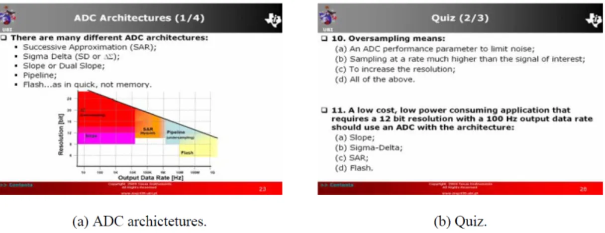
To convert an analogue signal to a digital value, it is necessary to use an ADC. This topic starts with a general description of the ADC specifications (DC and AC performances and ADC architectures). The analogue peripherals in a number of MSP430 family devices are sufficient to realize complete practical signal chains, with just a few passive components. Furthermore, the processing capabilities of the MSP430 are sufficient to implement some interesting real world signal processing tasks. Figure 1 shows slides exposing this topic and for a quiz question on it.
The first ADC architecture discussed is the Successive Approximation Register (SAR) converter that determines the digital word by approximating the input signal using an iterative process. SARs are adequate for general-purpose applications, being widely used in signal level applications such as data loggers, temperature sensors, bridge sensors, and as general purpose. TI offers both stand-alone SARs and integrated SARs in the MSP430. This section will focus the SAR ADCs integrated into the MSP430 devices. Each ADC is a single 10-bit or 12-bit unit, with a built-in sample-and-hold circuit, internal reference and autoscan features. The front end consists of a multiplexer circuit, allowing the developer to select one of eight external pins, or one of four internal sources.
The next ADC architecture described is of the Sigma Delta (SD) converter that determines the digital word by sampling and digital filtering. This topic start by clarifying the components of a SD converter (Delta modulator; Digital filter; Decimation digital filter; MSP430 SD16(A) – Sigma/Delta ADC), giving details of the SD converter contained in the MSP430 devices. Some devices dedicated to particular applications, such as portable medical, energy metering and generic application, contain up to 7 SD converters. The eZ430-F2013 hardware development tool includes a SD ADC. The module integrated into this device is the SD16_A that supports 16-bit analogue-to-digital conversions. The module implements a 16-bit SD core and reference generator. In addition to external analogue inputs,
internal supply voltage sense and temperature sensors are also available.
Analogue-to-digital conversion by integration is based on counting clock pulses. An ADC that uses an integration method is known as a Slope ADC. This technique can be implemented with a comparator rather than a standalone ADC module or device. The integration method relies on the charging/discharging of a capacitor and counting the number of clock cycles to do so. Longer discharge times indicate larger voltages. The voltage is derived from the discharge time using the standard equation for capacitor discharge. The on-board analogue comparator provided by the MSP430 is configurable, which allows mapping of external pins by inputs or outputs, with interrupt capabilities on either the rising or falling edges. This module is primarily designed to support precision slope analogue-to-digital conversions, battery-voltage supervision, and monitoring of external analogue signals. It is included in the FG4618 device fitted to the experimenter’s board.
Finally, at the end of the section are presented laboratory exercises, which develop applications that group together the use of the operational amplifier and the ADC. A different laboratory is developed for each kit, taking into account that both the ADC10 and the SD16_A laboratories implement a temperature data logger. The first laboratory implements a temperature data logger using the hardware kit’s integrated temperature sensor. The device is configured to perform an acquisition, using ADC10 and SD16, each minute for one hour. Each temperature’s (ºC) value is transferred to flash info memory segment B and C. When the microcontroller is not performing any task, it enters into low power mode.
The next laboratory examines the SAR ADC12 and Op-Amp modules using the MSP-EXP430FG4618 development tool (MSP430FG4618 device). The test voltage is generated by the digital-to-analogue converter. The analogue signal is conditioned by the Op-Amp module (amplitude change), configured as non-inverting Op-Amp. Afterwards, this signal is applied to the ADC12 input to be converted. The input and output values are compared. There is laboratory to analyse the Comparator_A operation. A voltage is applied to one of the Comparator’s inputs, generated either by the digital-to-analogue converter or by other external source. Whenever the external voltage value is higher than the comparison value internally generated, an interrupt is generated that switches the LED state.
This section covers in detail all the above topic, starting with the theory beneath each device giving the background, basic information about modules and their usage later through practical programming with top-down analysis (task solution) and bottom-up synthesis (code generation) expressing where and when to use what device. Besides the bibliography references presented above for the operational amplifiers section, the ADC section is developed with the knowledge included in [10-22].
Figure 1 – Slides of the covered topic and Quiz in the Data Acquisition section. 2.2 Digital-to-Analogue Converter
Nowadays, digital devices are used worldwide and have become integral parts of our daily lives. However, real world signals are analogue in nature. Thus, the final part of an analogue signal chain requires a digital to analogue conversion to be able to drive devices. Therefore, it is necessary to utilize an electronic circuit called a digital-to-analogue converter (DAC) to convert a digital representation of a quantity into an analogue electrical value. The DAC is the last element of a signal chain and the interface for the microcontroller to the real analogue world. The DAC converts digital signals to analogue electrical signals. This section presents the DAC architecture and operation and then develops an exercise to illustrate the concepts. The laboratory exercise implements a voltage ramp generator. The DAC module reference is obtained from the ADC module. The DAC is configured with 12-bit resolution, in straight binary format. The output of the DAC value is updated once every 1 msec by an interrupt service routine (ISR) generated by Timer_A. The two push buttons are used to manually modify the output of the DAC value. When the microcontroller is not performing any task, it enters low power mode. This section is supported by the references presented in the previous section.
2.3 Communications
An important feature of modern microprocessor based systems is their communication capability, that is, their ability to exchange information with other systems in the surrounding environment. The communications interfaces can be used for firmware update or loading local parameters. At a higher level, these interfaces can be used to exchange information in applications with distributed processes. The MSP430 contains built-in features for both parallel and serial data communication. This section describes the operation of these peripherals, and discusses the protocols, data formats and specific techniques for each type of data communication.
The communication modules available for the MSP430 family of microcontrollers are USART (Universal
Synchronous/Asynchronous Receiver/Transmitter), USCI (Universal Serial Communication Interface) and USI (Universal Serial Interface). These provide asynchronous data transmission between the MSP430 and other peripheral devices when configured in UART mode. They also support data transmission synchronized to a clock signal through a serial I/O port in Serial Peripheral Interface (SPI) and Inter Integrated Circuit (I2C) modes.
The USART (Universal Synchronous/Asynchronous Receiver/Transmitter) module is a base unit for serial communications, supporting both asynchronous communications (RS232) and synchronous communications (SPI). Although supporting RS232, SPI and I2C, the USCI (Universal Serial Communication Interface) module is a communications interface designed to interconnect to industrial protocols: LIN (Local interconnect Network), used in cars (door modules, alarm, sunroof, etc.); IrDA (Infrared Data Association), used for remote controllers. The USI (Universal Serial Interface) module offers basic support for synchronous serial communications SPI and I2C.
The first laboratory exercise explores the USCI module in UART mode that will be connected to a CCE IO console. When the connection is established, the character sequence written on the keyboard to the console will be displayed again on the console. The next laboratory explores the USCI and USI communication interfaces in SPI mode. The MSP430 devices included on the Experimenter’s board will exchange messages between themselves, one being the MSP430FG4618 (master) that will control operation of the other MSP430F2013 device (slave). The master, by reading the current state of the slave, will drive the slave to the new desired state, controlling its activity. In this particular case, switching the state of LED3 will be implemented. The last laboratory explores the USCI and USI communication interfaces in I2C mode. It uses the two MSP430 devices included on the Experimenter’s board: MSP430FG4618 as the master and the MSP430F2013 as the slave. The master receives a single byte from the slave as soon as a button is pressed. Besides the references exposed in the previous sections, this one is supported by [24-33].
2.4 Advanced Laboratories
After that all the functions and features of the MSP430 devices have been described, this last presents several advanced “full-fledged” laboratories that bring together many of the subjects discussed. It intends to give a sense of accomplishments to the students at the end of learning everything. Actual software (code) is given as a reference along with the “problem statement” but students can be challenged to develop the same application with limited resources such as memory, peripherals, external components or extend its capabilities. This will trigger their own thought process and let them work independently after the course completion.
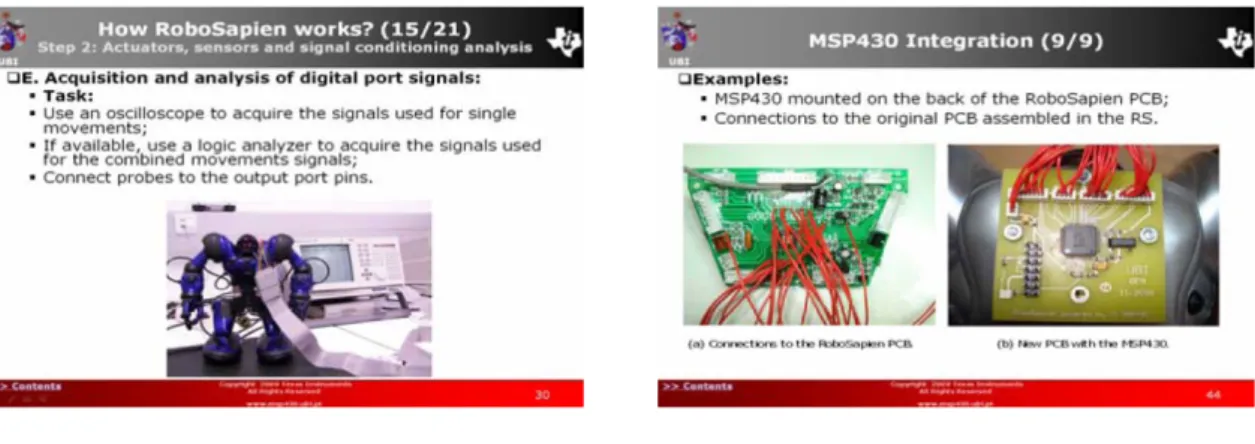
The first advanced laboratory consists of a new approach to teaching robotics, making use of the MSP430. It consists of the substitution of RoboSapien (RS) control and regulation electronics by the MSP430. The MSP430 replicates the RS operation, illustrating the capabilities of this microcontroller and as a way to motivate students. Figure 2 shows the PCB developed to include the MSP430 as the "brain" of the RoboSapien.
The second advanced laboratory focuses on the MSP430 communications peripherals. It consists of developing an eZ430-RF2500 communication application to show how these communications peripherals are configured in a practical application. The aim of this laboratory is to use some of these hardware development tools to communicate together, activating their LED in response to writing messages to the CCE console.
The third laboratory consists of a MSP430 assembly language tutorial. It includes examples using the different addressing modes and instructions format. It provides an overview of the fundamental characteristics of the assembly language instructions. It finishes with an assembly language project example: square root extraction with the CCE.
4. CONCLUSIONS
It was presented the teaching structure in the lectures that use microprocessors at the undergraduate and graduate Electrical related courses at the University of Beira Interior, Portugal that make use of microcontrollers, including signatures such as, Instrumentation and Measurements; Data Acquisition; Automation and Robotics; Industrial Informatics; Real Time Systems; Embedded Systems; Bionic Systems and Monitoring and therapy medical portable devices. The former last five signatures integrate several knowledge that are acquired during the courses. The first part of this paper presented the outline of the course. Particularly, its structure, and the initial subjects covering an introductory overview in logic design and embedded processors and a description of the available software and hardware development tools for the MSP430. The second part describes the MSP430 Architecture, Device Systems and Operating Modes, General purpose Input/Output and all the peripherals integrated in the MSP430 family devices.
This third part of the paper covers the description inside the course of the MSP430 data acquisition and communication peripherals integrated in its family devices. It ends with the presentation of advanced laboratories that make use of the knowledge acquired during the course.
The projects development making use of the microcontroller has proven to be a valuable teaching tool for motivating and stimulating the students, allowing the reinforcement of several key concepts discussed in undergraduate signatures. With this pedagogical approach, the students gain much more experience since they are challenged to develop, not overwhelming, but much more complex projects, while keeping them motivated.
ACKNOWLEDGMENTS
The authors thank the support given by Texas Instruments; and particularly the help provided by Robert Owen (TI University Programme Manager).
REFERENCES
[1] C. Nagy, Embedded systems design using the TI MSP430
series. Elsevier, Embedded Technology Series, 2003.
[2] Texas Instruments, MSP430x2xx Family, User’s Guide. SLAU144E, Texas Instruments, 2008.
[3] Texas Instruments, MSP430x4xx Family, User’s Guide. SLAU056G, Texas Instruments, 2007.
[4] Texas Instruments, MSP430x5xx Family, User's Guide. SLAU208, Texas Instruments, June 2008.
[5] F. Pereira, Microcontroladores MSP430: Teórica e
prática. 1ª Ed. Editora Érica, São Paulo, Brasil, 2005.
[6] J. Luecke, Analog and digital circuits for electronic
control system applications: Using the TI MSP430 microcontroller. Elsevier, Embedded Technology Series,
2005.
[7] B. Baker, "Elements of the analog signal chain," in Proc.
ATC 2008 – MSP430 Advanced Technical Conference,
Texas Instruments, Sonthofen, Germany, 2008.
[8] B. Baker, "Working with ADCs, OAs and the MSP430," in Proc. ATC 2006 – MSP430 Advanced Technical
Conference, Texas Instruments, Sonthofen, Germany,
2006.
[9] F. Vanselow, "Single chip embedded solutions using integrated Op Amps," in Proc. ATC 2005 – MSP430
Advanced Technical Conference, Texas Instruments,
Landshut, Germany, 2005.
[10] B. Baker, "A Glossary of Analog-to-Digital specifications and performance characteristics," Application Report
SBAA147A, Texas Instruments, 2008.
[11] H. Grewal, "Oversampling the ADC12 for higher resolution," Application Report SLAA323, Texas Instruments, 2006.
[12] K. Quiring, "Implementing an ultralow-power thermostat with slope A/D conversion," Application Report
SLAA129B, Texas Instruments, 2006.
[13] B. Baker and O. Escher, "SD ADC in multiplexed designs," in Proc. TI Design Forum, Texas Instruments, Tel Aviv, Israel, 2008.
[14] L. Westlund, "Introduction to MSP430 ADCs," in Proc.
ATC 2006 – MSP430 Advanced Technical Conference,
Texas Instruments, Sonthofen, Germany, 2006.
[15] L. Bierl, "Economic measurement techniques with the Comparator_A module," Application Report SLAA071,
Texas Instruments, October 1999.
[16] M. Mitchell, "Using integrated analog with the MSP430," in Proc. ATC 2008 – MSP430 Advanced Technical
Conference, Texas Instruments, Sonthofen, Germany,
2008.
[17] M. Oljaca and O. Escher, "Driving SAR A/D Converter: Effects of the wrong R-C on the Op Amp," in Proc. TI
Design Forum, Texas Instruments, Tel Aviv, Israel, 2008.
[18] T. Krueger, "Analysis of analog signals using the MSP430 ADCs," in Proc. ATC 2008 – MSP430 Advanced
Technical Conference, Texas Instruments, Sonthofen,
Germany, 2008.
[19] T. Hendrick, "Low power data acquisition: A critical choice for embedded systems," in Proc. ATC 2005 –
MSP430 Advanced Technical Conference, Texas
Instruments, Landshut, Germany, 2005.
[20] Z. Albus, "Getting precise with MSP430 Sigma-Delta ADC peripherals," in Proc. ATC 2005 – MSP430
Advanced Technical Conference, Texas Instruments,
Landshut, Germany, 2005.
[21] Z. Albus, "Streamlining the mixed-signal path with the signal chain on-chip MSP430F169," Analog Applications
Journal SLYT078, Texas Instruments, 2004.
[22] Z. Albus and S. Schauer, "Enabling low-cost A/D conversion solutions with Comparator_A+," in Proc. ATC
2005 – MSP430 Advanced Technical Conference, Texas
Instruments, Landshut, Germany, 2005.
[23] J. H. Davies, MSP430 Microcontroller basics. Elsevier Science, Newnes, 2008.
[24] C. Hernitscheck, "Introduction to MSP430 communication interfaces," in Proc. ATC 2006 – MSP430
Advanced Technical Conference, Texas Instruments,
Sonthofen, Germany, 2006.
[25] D. Grini, "RF basics, RF for non-RF engineers," in Proc.
ATC 2006 – MSP430 Advanced Technical Conference,
Texas Instruments, Sonthofen, Germany, 2006.
[26] M. Morales, "Selecting the right RF protocol for your MSP430 application," in Proc. ATC 2008 – MSP430
Advanced Technical Conference, Texas Instruments,
Sonthofen, Germany, 2008.
[27] M. Raju and S. Schauer, "New high performance, dual communication module – USCI," in Proc. ATC 2005 –
MSP430 Advanced Technical Conference, Texas
Instruments, Landshut, Germany, 2005.
[28] P. Thanigai, "Using the USI I2C code library,"
Application Report SLAA368, Texas Instruments,
September 2007.
[29] T. Kot, "Software I2C slave using the MSP430,"
Application Report SLAA330, Texas Instruments,
September 2006.
[30] U. Kretzschmar and C. Hernitscheck, "Using the USCI I2C master," Application Report SLAA382, Texas
Instruments, December 2007.
[31] U. Kretzschmar and C. Hernitscheck, "Using the USCI I2C slave," Application Report SLAA383, Texas
Instruments, December 2007.
[32] V. Rzehak, "In-depth with MSP430’s new communication interfaces," in Proc. ATC 2006 – MSP430 Advanced
Technical Conference, Texas Instruments, Sonthofen,
Germany, 2006.
[33] Z. Albus, "Powerful yet simple: Low-cost serial communication with the new USI module," in Proc. ATC
2005 – MSP430 Advanced Technical Conference, Texas