Javier Ortega Heras
Safety analysis of modern
heritage masonry buildings:
Box-buildings in Recife, Brazil
Safe
ty anal
ysis of moder
n her
it
ag
e masonr
Bo
x-buildings in R
ecife, Brazil
Ja
vier Or
teg
a Her
as
20 13Safety analysis of modern
heritage masonry buildings:
Box-buildings in Recife, Brazil
DECLARATION
Name: Javier Ortega
Email: johe00@gmail.com
Title of the MSc Dissertation:
Safety analysis of modern heritage masonry buildings: Box-buildings in Recife, Brazil
Supervisor(s): Professor Paulo B. Lourenço
Year: 2013
I hereby declare that all information in this document has been obtained and presented in accordance with academic rules and ethical conduct. I also declare that, as required by these rules and conduct, I have fully cited and referenced all material and results that are not original to this work.
I hereby declare that the MSc Consortium responsible for the Advanced Masters in Structural Analysis of Monuments and Historical Constructions is allowed to store and make available electronically the present MSc Dissertation.
University: University of Minho, Guimarães, Portugal
Date: 12th July 2013
ACKNOWLEDGEMENTS
First of all, I would like to thank the SAHC Consortium for giving me the opportunity to participate in this Masters Course, which has been an invaluable experience, and for trusting me with the scholarship, without which this experience could not have been possible.
I am particularly grateful to my supervisor, Professor Paulo Lourenço, for his patience, availability and guidance during the dissertation. It has been a pleasure and a unique experience working with him. Many thanks, as well, to João M. Pereira, who has enormously helped me using DIANA and has patiently listened and answered to all my doubts.
I also would like to thank every lecturer I was lucky to have during the Masters Course in Padova and Guimarães. From the University of Padova I am especially grateful to Giulia Bettiol, who was an amazing supervisor during the integrated project.
Many thanks to all my friends I was lucky to meet in Padova and Guimarães. They are the people responsible for this unforgettable year, which has been also full of laughs and good moments, and from whom I have learned a lot.
Finally, I cannot be thankful enough to my parents and their endless support and encouragement, and to Marieta, for being always there with me.
ABSTRACT
There was a large increase in the construction of public housing in Brazil during the 1970s because of housing shortage and economic policies supporting development projects and private investments. Box-buildings arose in that time, constructed by non-experts interested only in a fast return on the investment. These buildings were made in an empirical way, with no consideration of specific technical norms or standards and thus, critically reducing their safety coefficient. Now, it is estimated that there are between 4,000 to 6,000 buildings constructed with these characteristics in the Recife Metropolitan Region. They are inhabited by more than 250,000 people, comprising approximately 10% of the population of this region. Around 90% of these buildings seem to present some risk of collapse, with different severity. 230 buildings are at high risk of collapse and have been evacuated. More than 100 buildings have been condemned, 5 have been demolished and 12 have already collapsed.
The present dissertation focuses on a recent PhD thesis co-supervised at University of Minho carried out by de Carvalho (2010) and aims to extend it. That work is an experimental and numerical research applied to one building that suffered collapse. An extensive testing programme was carried out, including non-destructive and minor destructive testing on the building, as well as laboratory testing. A finite element model was made, updated with the data obtained through the dynamic identification, and a linear elastic numerical analysis was performed. The objective of the present dissertation is to extend the work carried out before to the non-linear regime, by incorporating the inelastic phenomena, aiming at quantifying the safety of the existing buildings and better understanding the damage and the reasons for the collapse. The research mainly comprises a safety analysis of the structure and a sensitivity analysis, in order to understand the importance of the material parameters and their influence on the structural response of the building.
RESUMO
A construção de habitação social no Brasil teve um grande impulso a partir da década de setenta devido à escassez de habitação, incentivada pelas políticas económicas que facilitaram os projetos de desenvolvimento do país na época e o investimento privado. Os prédios tipo caixão emergiram naquela época, construídos por profissionais sem experiência em construção, interessados apenas no rápido retorno desse tipo de investimento. A maior parte destas edificações foram executadas de forma empírica, sem consideração dos requisitos de regulamentação técnica específicas que possibilitassem o estabelecimento de um nivel de segurança estrutural aceitável. Atualmente, estima-se que existam entre 4,000 a 6,000 edifícios com essas características construídos na Região Metropolitana do Recife (RMR) e que estes sejam habitados por cerca de 250,000 pessoas, compreendendo aproximadamente 10% da população do grande Recife. Cerca de 90% destes edifícios apresentam risco de colapso, sendo que 230 são considerados de alto risco e já foram evacuados. Mais de 100 prédios foram interditados, 5 foram demolidos e 12 sofreram colapso.
O presente trabalho centra-se numa recente tese de doutoramento coorientada na Universidade do Minho realizada por de Carvalho (2010) e pretende continuar o seu trabalho. Aquela tese é uma investigação experimental e numérica aplicada a um edifício que colapsou. Foram realizados no edifício ensaios não destrutivos e semi-destrutivos, tendo ainda sido executados ensaios em laboratório de amostras retiradas das paredes do edifício. Por outro lado, realizou-se um modelo de elementos finitos, atualizado com as informações obtidas por meio de um ensaio de identificação dinâmica realizado no edifício, e completou-se uma análise elástica linear. O objetivo do presente trabalho é alargar o trabalho feito na tese para uma análise em regime não linear, incorporando a resposta inelástica para quantificar a segurança desses edifícios, entender melhor os danos e tentar identificar as causas do colapso. A investigação compreende principalmente uma análise da segurança da estrutura e uma análise de sensibilidade, a fim de entender a importância das características dos materiais e a sua influência sobre a resposta estrutural do edifício.
RESUMEN
Durante los años 70, hubo un gran aumento de la construcción de vivienda pública debido a la escasez de vivienda y las políticas económicas que apoyaban proyectos de desarrollo y la inversión privada. Los edificios tipo caixão surgieron en ese momento, construidos por profesionales sin experiencia en el campo de la construcción e interesados solamente en el rápido retorno de la inversión. Los edificios se construían de manera empírica, sin consideraciones a las normas y códigos de la época y por ello, el coeficiente de seguridad de los edificios se redujo drásticamente. Actualmente, se estima que hay entre 4,000 y 6,000 edificios construidos de esta manera en el área metropolitana de Recife (RMR). Están habitados por más de 250,000 personas, lo que comprende aproximadamente al 10% de la población total de la región. Alrededor del 90% de estos edificios presentan algún riesgo de colapso y de los cuales 230 están considerados en alto riesgo y ya han sido evacuados. Más de 100 están pendientes de demolición, 5 han sido ya demolidos y 12 han colapsado.
El presente trabajo pretende continuar el trabajo empezado en la tesis doctoral realizada por de Carvalho (2010) y codirigida en la Universidade do Minho. La tesis es una investigación numérica y experimental sobre un edificio que colapsó. Se llevó a cabo un extenso programa de ensayos que incluyó ensayos no destructivos y semi-destructivos sobre el edifico, y trabajo experimental en laboratorio, con muestras extraídas del edificio. Se realizó un modelo de elementos finitos, actualizado con la información obtenida a través de un ensayo dinámico que se desarrolló sobre el edificio, y se llevó a cabo un análisis elástico lineal. El objetivo del presente trabajo es ampliar el trabajo realizado en la tesis llevando el análisis al régimen no lineal, incorporando la respuesta inelástica para así cuantificar la seguridad de este tipo de edificios y entender mejor los daños y las razones del colapso. La investigación comprende principalmente un análisis de la seguridad de la estructura y un análisis de sensibilidad, con el fin de comprender la importancia de las características de los materiales y su influencia en la respuesta estructural del edificio.
TABLE OF CONTENTS
1.
INTRODUCTION... 1
2.
CONTEXT AND RESEARCH IN BRAZIL ... 3
2.1 Geographical context ... 3
2.2 Box-buildings – “Prédios tipo caixão” ... 4
2.2.1 Historical and socio-economical context ... 4
2.2.2 Building typology... 5
2.2.3 Collapsed buildings ... 7
2.2.4 Current situation ... 8
2.3 Research in Brazil ... 9
2.3.1 Anomalies encountered and identification of causes ... 9
2.3.2 Mechanical characteristics and structural behaviour of the masonry ...11
2.3.3 Repairing and strengthening interventions...13
2.4 Conclusions ...13
3.
DESCRIPTION OF THE BUILDING ... 15
3.1 Location ...15
3.2 Characterization ...16
3.2.1 Building overview ...16
3.2.2 Material and structural survey ...18
3.3 Testing and obtained data ...22
3.3.1 In situ investigation ...22
3.3.2 Laboratory investigation ...26
3.4 Conclusions ...32
4.
SAFETY ANALYSIS ... 33
4.1 Finite element model ...33
4.1.1 Loads ...34
4.1.2 Calibration of the finite element model...37
4.1.3 Material properties ...39
4.2 Safety analysis ...39
4.2.1 Only vertical loading...40
4.2.3 Vertical loading without rendering ... 50
4.3 Conclusions... 54
5.
SENSITIVITY ANALYSIS ... 55
5.1 Collapse of the building ... 55
5.1.1 Current condition ... 56 5.1.2 Collapse assessment ... 59 5.2 Sensitivity analysis ... 62 5.3 Conclusions... 68
6.
CONCLUSIONS ... 71
6.1 General conclusions ... 71 6.2 Further research ... 72REFERENCES ... 73
ANNEX A: RESULTS OF THE GEOMETRICAL NONLINEAR ANALYSIS ... 75
1. INTRODUCTION
There are thousands of structural masonry buildings in Brazil. The so-called box-buildings arose in the Recife Metropolitan Region (RMR) during the seventies and currently about 5,000 of them exist. Twelve of these buildings have already collapsed while 230 are at very high risk of collapse. The main problems seems to be a poor choice of materials and the adoption of technically inadequate building solutions due to the low cost and high speed construction, but the reasons for the collapse are still unclear. Many research projects have been carried out in Brazil concerning this problem but the characterization of the materials is particularly difficult, given the low quality of the materials and the many factors which seem to be affecting them. The anomalies encountered are not only a result of inadequate materials and defects in construction works but are also affected by the lack of maintenance by the inhabitants and different environmental causes, such as moisture or chemical attacks.
This problem of the box-buildings in Recife affects more than 250,000 people who inhabit them, approximately 10% of the population of the RMR. It is a major social problem that has caught also the attention of public organisms and national newspapers, see Figure 1. It is very common to see social housing in very poor condition and extremely deteriorated, which is a typical situation in many different countries. Efforts in rehabilitation and conservation need to also address this modern heritage which involves social housing and modern buildings.
Figure 1. Newspapers covering information related with the box-buildings
The methodology used for the conservation cannot apply the conventional structural analysis techniques and legal codes or standards oriented to the design of modern constructions. Repairing and strengthening techniques and the methodology for inspection and diagnosis have been substantially developed in the last years. Significant advances have been made in experimental research (in situ and laboratory) and in tools for advanced numerical analysis. The possibility of using sophisticated numerical models for the analysis of structures and for structural safety assessment has been highly enhanced in the recent years. Conservation engineering is a multidisciplinary approach that needs a full understanding of the materials and the structure, and aims at acquiring enough data to prevent inadequate interventions. The present dissertation intends to apply this distinct
methodology for inspection and diagnosis of historic constructions to these conventional buildings so it can help future research to find an adequate solution to this relevant problem.
Therefore, the primary objective of the present research is to determine the safety of this type of buildings, understand their structural behaviour and evaluate the adequacy of using and advanced structural analysis tool for their safety assessment. This objective will be achieved by performing a safety analysis, considering the applicable load combinations, and a sensitivity analysis, repeating a reference analysis for different material properties.
The analysis will be performed on a typical box-building of the Recife Metropolitan Region that collapsed on December 2007. Therefore, a second primary objective was defined, aiming at determining the reasons for the collapse and better understand the damage. The failure of the building and the observed damage will also become a good reference to validate the results obtained from the numerical analysis. The analysis will be made using the finite element software DIANA. A model was previously prepared by de Carvalho (2010), but the objective is to adapt it to the new requirements. A full understanding of the case study in terms of construction, structural system and materials is also a main objective of the present work. The extensive experimental research and the visual inspection carried out by de Carvalho (2010) are the basis for the exhaustive description of the building that this research intends. His work is here reviewed and synthesized.
Finally, the context of the present research is also briefly addressed, aiming: to review the geographical, historical and socio-economical context of the box-buildings; to define the current situation of the box-buildings in the RMR; to review the past collapse cases, identifying the causes reported for the collapses; and to review the state of the art of the research in Brazil focused on the box-building typology problem.
2. CONTEXT AND RESEARCH IN BRAZIL
2.1 Geographical context
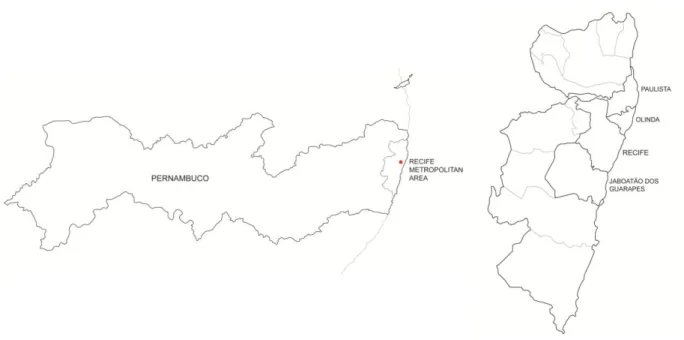
The Recife Metropolitan Area is the fifth largest urban metropolitan area in Brazil and the largest in the Northeast of Brazil. Its population is over 3,700,000 inhabitants with a density of over 1,300 inhabitants per km2 and Recife belongs to the state of Pernambuco. Figure 2 situates the area within Brazil.
The box-buildings (known as “prédios tipo caixão” in Brazil) arose and developed in the Recife Metropolitan Area, called RMR (“Região Metropolitana do Recife”). In particular, they were mostly built in the cities of Recife, Olinda, Jaboatão dos Guarapes and Paulista (Figure 3). The collapses and problems described in the following sections occurred in these cities.
Figure 3. Situation of the RMR within the State of Pernambuco (left) and location of the cities where most of the
accidents related to the box-buildings occurred within the Recife Metropolitan Area (right).
Geographically, due to the proximity to the equator, the weather in Recife is generally warm with no extreme temperatures. Climate is tropical with high relative humidity throughout the year and high rainfall. Recife has tropical forests and presents two types of landscapes: the hills and the plain. Historically, the city of Olinda in the RMR is the second oldest Brazilian city and its historic downtown area, considered one of the best preserved colonial cities in the country, was declared World Heritage Site by the UNESCO. Olinda is also a major cultural centre in Brazil.
Economically, Recife is the wealthiest city in the Northeast of Brazil and one of Brazil main economic hubs, primarily because of the presence of one International Airport and two International ports. Services are the largest economy contributor but Recife has also an important industrial area with an important technological centre.
2.2 Box-buildings – “Prédios tipo caixão”
2.2.1 Historical and socio-economical context
There was a large increase in the construction of public housing in Brazil during the 1970s because of housing shortage and economic policies supporting development projects and private investments. Box-buildings arose in that time, constructed by non-experts interested only in a fast return on the investment. These buildings were made in an empirical way, with no consideration of specific technical norms or standards, thus, critically reducing their safety coefficient.
In this period, there was a rural exodus towards the cities, bringing great masses of workers without housing, which accumulated on the peripheries of the urban centers. The insufficient economic power of the inhabitants of these buildings led to low construction costs to afford economically viable
housing. Therefore, certain essential structural elements were often suppressed, such as concrete tie beams and lintels, and technically inadequate buildings solutions were adopted.
The box-buildings are a result of speculative activities, with low cost and high speed construction combined with unskilled labour. After construction, a fast progressive degradation process occurred, with a premature ageing and pathological manifestations that are compromising the safety of the buildings.
Now, it is estimated that there are between 4,000 to 6,000 buildings constructed with these characteristics in the region. They are inhabited by more than 250,000 people, comprising approximately 10% of the population of the RMR.
2.2.2 Building typology
The box-buildings are structural masonry housing buildings named as such because of their shape. The following section aims to describe the common features and characteristics of this type of construction regarding appearance, structural system and materials.
Building overview
The buildings are typically four storeys high, generally with four apartments per floor. The total height of the buildings does not exceed 14 m. In the central part of the building there is a staircase, which is usually the only part of the building with reinforced concrete elements. On top of the staircase there is usually an upper water reservoir also built in concrete. Figure 4 shows the general appearance of these buildings.
Figure 4. Example of box-buildings in Recife.
The layout of the floors consists of two parts separated and communicated by the central staircase, resulting in an H shape plan configuration. The maximum span covered by the slabs are in the range of 2,75-3,25 m. Figure 5 shows a typical example of the plan and layout of a box-building.
Structural system
The structure consists of unreinforced masonry walls. They are usually constructed with hollow clay brick masonry with 9 cm thickness, rendered with mortar. Although this masonry type is not conceived
as load bearing, the walls support load beyond their own weight. They bear the floor slabs and transfer the loads to the foundation. In addition, they act as partition and enclosure walls.
Figure 5. Generic plan of a box-building (left) and roof plan with the upper reservoir (right). (Araújo, 2010).
The staircase is positioned in the central part of the block and is usually built in concrete, serving as the support of the upper water reservoir. However, it is observed that, in some cases, this reservoir is supported directly by the masonry walls.
Slabs are mostly ribbed pre-cast concrete with clay or concrete tiles and a cast in situ concrete compression layer. The slabs are usually directly supported on the walls. The roof structure is usually made in timber and is covered in cement or ceramic tiles. The structure rests on timber joists supported by the walls.
There are additional concrete structural elements that can only be found in some buildings, such as concrete tie-beams in the connection between the walls and the foundation or in the connection between the walls and the floor slabs. The absence of lintels over the openings in the masonry is also common.
Concerning the foundations, there is a transition structure between the ground floor pre-cast concrete slab and the foundations, which are mostly continuous reinforced concrete footings in inverted T shape, settled upon a mud slab. This structure normally consists of single leaf clay masonry walls, externally rendered with mortar and with no waterproofing. Note that, frequently, in Recife the ground water table is very superficial, under 1 metre, and thus, foundations are in direct contact with water. The space between the ground floor and the continuous footing is usually filled with soil or sand, but, in occasions, it is left empty. This technique is known as caixão vazio and makes the structure more vulnerable to the lateral thrust of the land and to the accumulation of water, creating a potentially aggressive environment for the foundation elements that compose it.
Material survey
The masonry walls are built with hollow clay blocks with dimensions about 90 x 190 x 190 mm3 with 6 or 8 holes positioned horizontally. They lay on the smaller dimension, 90 mm, according to the common practice used in the region. Regarding the hollow clay blocks, the variability in the size and colour is noteworthy, revealing insufficient control on the manufacturing process. Research about the quality of the masonry blocks in the Brazilian industry confirmed the poor quality of the units, failing to meet the requirements of the standards generally prevailing at the time (de Melo, 2007).
Generally, external and internal renderings consist of cement or cement-lime mortars of variable thickness, as the external rendering can reach up to 6 cm. The average total thickness of the masonry wall is therefore around 13 or 14 cm. Mortar joints dimensions also vary widely in thickness, indicating poor control of the construction processes and of the hollow block manufacturing.
2.2.3 Collapsed buildings
Over the past 20 years, a total of 12 box-buildings have collapsed in the RMR, causing 12 casualties. The most significant cases are described next.
On March 1994 in Recife, the collapse of one of the blocks of the residential complex Bosque das Madeiras occurred during the construction works. There were no casualties and the main cause reported was the execution of openings in a central partition wall to allow the installation of pipes. On April 1997 in Jaboatão dos Guarapes, the Aquarela building collapsed. The building had been built 11 years before, in 1986. The existence of tie-beams at the floor levels avoided the complete collapse of the building. There were no casualties and the assumed main cause for the collapse was the loss of strength of the masonry walls in the foundations as a result of moisture. The typology was that of caixão vazio.
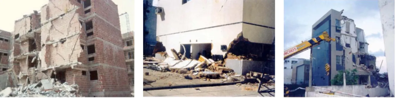
On November 1999 in Olinda, the Ericka building collapsed causing 5 casualties. It was also built 11 years before, in 1988. The most probable cause for the collapse was the advanced state of deterioration of the masonry units in the foundation walls due to the continuous exposure to sulphate attack. The foundations were built using caixão vazio. Figure 6 shows these buildings after the collapse.
On December 1999 in Olinda, the collapse of the block B of the complex Enseada do Serrambí occurred, causing 7 fatalities. The age of the building was 9 years. The failure of the foundation masonry walls was reported to be the main cause for the collapse. The foundations were again constructed with caixão vazio. Note that the building suffered a complete collapse due to the absence of tie-beams at the floor levels.
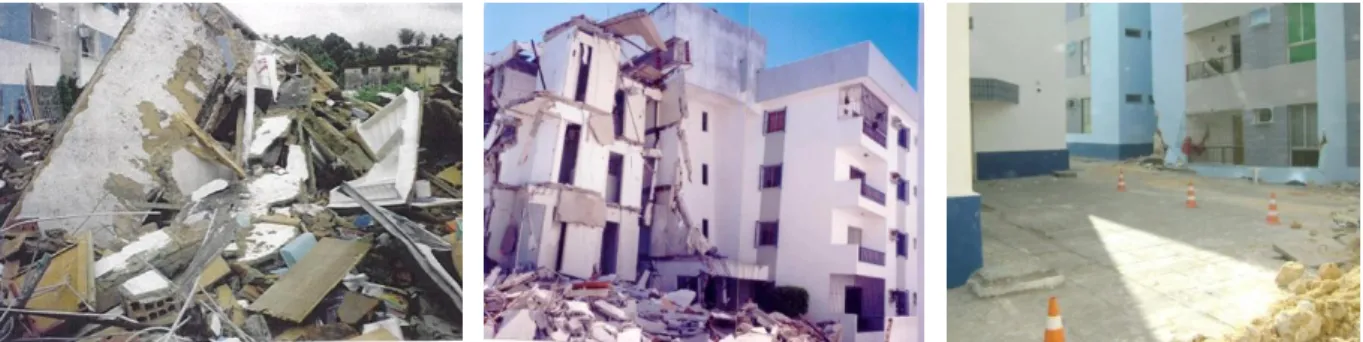
On May 2001 in Jaboatão dos Guarapes, the Ijuí building collapsed with no casualties. It had been constructed just 6 years before, in 1995. The assumed main cause for the collapse was the failure of the continuous footings in the foundations as a result of the passage of wastewater and rainwater due to the natural slope of the terrain. Figure 7 shows these buildings after the collapse.
On December 2007 in Jaboatão dos Guarapes, the partial collapse of the foundation masonry walls of the block B of one of the buildings of the residential complex Sevilha took place. The building sank more than 1 meter in the central part as it can be observed in Figure 7. The present dissertation is focused on this particular case.
Figure 7. From left to right, view of the buildings of Serrambí, Ijuí and Sevilha after the collapse
Most of the accidents that occurred in these box-buildings occurred suddenly and presenting no evidence of damage or cracks that could predict the collapse.
The ratio of accidents that occurred in relation to the number of buildings of this type is 1:500, much higher than the maximum common desirable value of 1:100000 for 50-years’ service life. It is thus a major problem, not only technical but also social because people are exposed to a loss of property and life is threatened.
2.2.4 Current situation
Nowadays, there are over 6,000 box-buildings in the RMR. Around 90% of these buildings seem to present some risk of collapse, with different severity (de Melo, 2007). 230 buildings are at high risk of collapse and have been evacuated. More than 100 buildings have been condemned, 5 have been demolished and 12 have already collapsed. Table 1 summarizes the situation in the most affected cities.
Table 1. Situation of the box-buildings in the RMR (de Melo, 2007)
City Number of buildings Condemned buildings Demolished buildings
Olinda 511 102 2
Jaboatão dos Guarapes 972 10 2
Paulista 608 10 0
Recife 2,242 - 1
Total 4,333 122 5
This is one of the major urban problems in Recife. The problem is very serious due to the large number of buildings involved. Evacuation of buildings has already affected many residents, generally low income families, while others fear to continue in an area where buildings have collapsed, living with a high risk. However, there are also some families that illegally are living in some of the evacuated buildings.
2.3 Research in Brazil
Several research projects have been carried out in Brazil concerning the problem. Research has been done on the causes responsible for the collapse and restriction of access for the box-buildings, on the mechanical characteristics and structural behaviour of the masonry used, and on possible interventions for the strengthening and repairing of these buildings. A discussion of the state of the art on these topics in Brazil is therefore presented below.
2.3.1 Anomalies encountered and identification of causes
Nowadays, many buildings present an advanced deterioration state that led to their evacuation and collapse. Most of the anomalies encountered were reported to have happened during the construction works, due to an incorrect design. As previously stated they are the consequence of extreme cost reduction, high speed construction and unskilled labour. De Melo (2007) investigated the anomalies reported in technical inspections and classified them according to the cause of the problem:
Failure or inappropriate design: The box-buildings were built in an empirical way, with no regard of specific technical norms or standards. Therefore it is frequent to observe insufficient mechanical properties of the structural elements to bear the stresses to which they are exposed and the subsequent appearance of cracks.
Technically inadequate constructive solutions were adopted, such as the use of caixão vazio and the use of masonry walls with no waterproofing in the foundations. These solutions have caused many problems such as the flooding of the basements and consequent water related pathology.
Also, the low cost and reduction of construction time led to the suppression of important concrete structural elements like tie-beams and lintels.
Low quality and inadequate materials: The low quality of the bricks used in Brazil at that time is also reported, which generally did not comply with the applicable norms. Part of the Brazilian industry followed empirical production processes with insufficient control on the raw materials and the manufacturing process. Therefore, numerous defects on the units can be observed, such as geometrical and dimensional flaws, cracks and, ultimately, insufficient strength and low durability. These anomalies result from a lack of adequacy and rigor in the selection of materials. High porosity masonry blocks are reported to have been used in the foundations together with low quality mortar. Failures and defects in construction works: The structural masonry walls were executed with hollow clay blocks of 9 cm thickness with horizontal holes. Researches show that these bricks are inadequate and a threat to structural masonry (Duarte, 2007). Also, the use of 9 cm bricks resulted in very slender walls, with values of slenderness much higher than the ones recommended by the codes. Moreover, the presence of caixão vazio resulted very vulnerable to the lateral thrust of the soil.
In addition, alterations of the original projects during the construction works have been reported, namely with additional loads, as another cause for the appearance of cracks and other anomalies. Inadequate use and lack of maintenance: Actions and modifications carried out by the inhabitants of the buildings compromised the safety of the buildings, such as the demolition of partition walls, changes in electrical and water services, excessive loading and change in use.
The lack of maintenance that most of these buildings present is also remarkable and clearly visible in the general appearance of the building, especially in the facade, but also in the roof and in the building services, with the presence of water leakage.
Environmental causes: Moisture expansion in the masonry has been observed in many cases. This expansion causes tensile stresses in the masonry walls and induces cracking. The fact that the foundations of these buildings are executed in masonry with no waterproofing and that the ground water table is very superficial facilitates the occurrence of this phenomenon. The phenomenon is further enhanced if the foundations present caixão vazio, which allows to retain the water inside the basement.
Different chemical attacks were also reported, especially sulphate attacks coming from the contaminated water from the sewage. This highly deteriorates the masonry of the foundations, affecting mostly the mortar.
Swelling of the masonry elements due to variations in the temperature and humidity conditions seems to have been observed. This phenomenon can also provide cracking that accelerates the degradation process of the building.
Other causes: Other anomalies observed that may have led to condemned buildings and their collapse, which do not belong to any of the previous groups are cracks induced by other reasons and corrosion of reinforcement.
2.3.2 Mechanical characteristics and structural behaviour of the masonry
Research conducted on the compressive strength of the masonry walls of the box-buildings have shown that this is excessively low, in the order of 2 MPa, and insufficient to bear the stresses to which they are exposed, particularly in the lower floors. Tests in compression, flexure and shear showed that these bricks are inadequate to be used for structural masonry buildings and they should have only been used as non-loadbearing elements.
Blocks with horizontal holes were introduced in Brazil at the beginning of the 1960s and soon became very popular as infills for buildings with a reinforced concrete structure. Later, these blocks were also used in the construction of buildings up to 4 floors with structural masonry walls.
Tests performed revealed the importance of the direction of the holes regarding the compressive, the flexural and the shear strength (Duarte, 2007). Table 2 shows the differences in the compressive strength of masonry units and masonry prisms with horizontal or vertical holes which feature a severe orthotropic behavior. The results also showed sudden collapse of the masonry units with horizontal holes. These characteristics are unsuitable for structural materials that should be able to provide some ductility.
Table 2. Compressive strength of masonry units and prisms according to the direction of the holes (Duarte, 2007)
Masonry units Masonry prisms
Direction of holes Horizontal Vertical Horizontal Vertical
Compressive strength (MPa) 0,79 8,28 0,43 3,07
Coefficient of variation (%) 38 18 44 24
The flexural and shear strength also proved to be strongly influenced by the direction of the holes, showing much lower values than those recommended for structural masonry.
Furthermore, it was found that the mortar rendering has a significant influence on the compressive strength and the failure mode of the masonry. Tests performed on non-rendered prisms and on prisms with rendering of different thickness (Mota, 2006) showed that the rendered prisms present higher compressive strength, depending on the mortar composition. The tests also revealed, as expected, that the lower the compressive strength of the masonry unit, the greater the influence of the mortar rendering.
Table 3 shows the compressive strength of the different prisms tested and Figure 8 shows the different failure modes observed. Note that the specimens are usual cross sections for a masonry wall of a box-building. The tests performed on prisms and walls indicated that the rendering contributes to an increase in the load capacity and its presence may be responsible for the stability of many of these buildings.
Table 3. Compressive strength of the prisms tested. Two different classes of cement mortar were used, with
different mortar mixed. (Mota, 2006)
Prisms Compressive strength
(MPa) Variation (%) Increment (%) P1 (non-rendered) 1,96 9,2 - P2 (thin rendering) 2,23 9,9 13,8 P3 (2 cm weak) 3,38 7,4 72,5 P4 (2 cm strong) 4,53 8,7 131,1 P5 (3 cm weak) 3,51 10,3 79,1 P6 (3 cm strong) 4,66 13,1 132,7
Figure 8. Failure modes of the prisms: non-rendered, with a 2 cm rendering and with a 3 cm rendering. (Mota,
2006)
Moreover, the mechanical properties of the masonry in saturated conditions were analyzed. Many of the foundations of the box-buildings are located in areas subjected to tidal flows and high level of the ground water table. A direct consequence of this problem are the constant cycles of wetting and drying that are imposed to the structure and its exposure to the aggressive agents present in these waters, which come from the contamination generated by the precarious sanitation system in various areas of the RMR.
Compressive tests were conducted for the evaluation of the compressive strength of ceramic blocks under different exposure conditions (de Oliveira, 2009). They simulated the situation in which they can be found within the building: dried, immersed in water and immersed in contaminated water.
An analysis of these results shows that the saturation of the elements tends to reduce the compressive strength of the clay blocks. The worst results were obtained for the blocks immersed in contaminated water, possibly due to the presence of deleterious agents in the groundwater, a fact that may have contributed to the deterioration of the clay units. Table 4 shows the results found.
Table 4. Results obtained from the compressive strength tests on hollow clay blocks. (de Oliveira, 2009) Compressive strength (MPa) Coefficient of variation (%) Dried 2,36 13,9 Immersed in water 2,31 11,7
Immersed in contaminated water 2,19 10,1
Finally, it was also observed that the collapse of the buildings did not occur necessarily at the more heavily loaded wall. Deterioration of the materials may be decisive and hence, it is not possible to establish the safety coefficients based solely on mechanical strength criteria.
2.3.3 Repairing and strengthening interventions
Currently, there is a lack of an efficient procedure for the adequate strengthening or repairing of these constructions. Several different interventions with questionable success have already been carried out and other solutions have been studied, but still not implemented.
Among the previous designed interventions, it is possible to state the creation of a reinforced concrete structural grid within the box-building, with subsequent decrease of space and loss of functionality; strengthening of the structure with new mortar; and jacketing of the masonry and foundations. In addition, demolition and reconstruction of the buildings were also adopted.
The different approaches that have been researched are the local repairing, by the introduction of connectors or resisting components, the elimination of structural irregularities, in order to simplify the load path, the global structural stiffening of the structure, and the ductility enhancement.
Several proposals consider the use of steel as a solution for strengthening this type of buildings by providing ductility to the system and thus eliminating the possibility of sudden failure. For instance, Siqueira (2010) proposed the use of a steel structural grid within the building that could take over the load in case of masonry failure.
2.4 Conclusions
The problem of the box-buildings in Brazil has been reviewed, stressing the large number of buildings and people involved. Collapses have caused 12 casualties and more than 100 buildings are now condemned. Other buildings might be unsafe and there is an urgent need to find a solution to this problem. Given the precarious conditions of these buildings, it is important to quantify the safety of the still standing buildings and to better understand the damage and their general structural behaviour. These are the main objectives of the present dissertation.
The state of the art of the research in Brazil has also been reviewed. The research carried out indicated the unsuitability of the masonry used in the buildings, with rather low mechanical
characteristics, insufficient to bear the stresses to which they are subjected to, and the inadequacy of some constructive solutions adopted, which have compromised the structural safety of the buildings. Failure or insufficiency in the design, defects in the construction works, low quality or inadequate materials, environmental causes, inadequate use and lack of maintenance are the most common causes reported for the collapses and evacuations of the buildings. The problems were a result of reducing construction costs, high speed construction and unskilled labour, and they have led to a fast degradation of the constructions, which have collapsed within the first 10 years of age.
There is still a lack of a methodology to strengthen and repair these buildings and there is no procedure that has proven to be efficient in the structural repair of this type of buildings.
The present dissertation focuses on the work carried out by de Carvalho (2010) and aims to extend it. His work is an experimental and numerical research applied to one building that suffered collapse. An extensive testing programme was carried out, including non-destructive and minor destructive testing on the building, as well as laboratory testing. A finite element model was made, updated with the data obtained through the dynamic identification, and a linear elastic numerical analysis was performed. Hence, the main objective of the presentation is to incorporate the inelastic phenomena to the analysis in order to quantify the safety of the existing buildings and better understand the damage.
3. DESCRIPTION OF THE BUILDING
3.1 Location
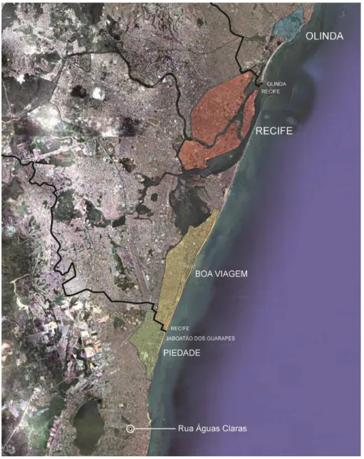
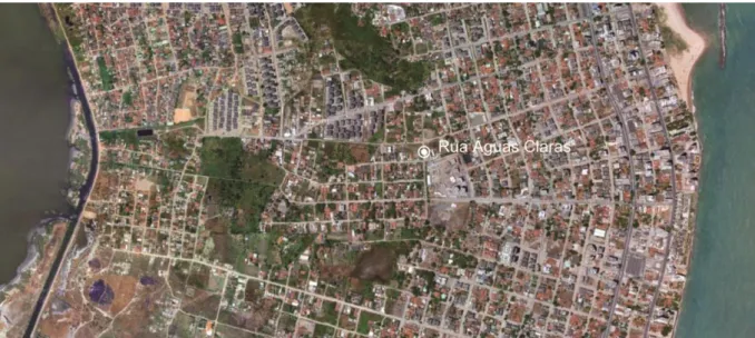
This research is focused on one of the box-buildings of the residential complex Sevilha, located in Rua Águas Claras, in Piedade, Jaboatão dos Guarapes within the Região Metropolitana do Recife (Figure 9). The street is close to the sea, within a residential area called Candeias, occupied mostly by low-rise housing (Figure 10). This residential complex is composed by four blocks of very similar characteristics, Block B of the complex partially collapsed in 2007 due to the failure of the foundation masonry walls and was later demolished (Figure 11). Its collapse triggered the experimental and numerical research carried out by de Carvalho (2010), which provided the information for the present work. The testing programme described next was performed on the block C of the complex, which has exactly the same characteristics.
Figure 10. Rua Águas Claras located in the low-rise housing area of Candeias
Figure 11. Process of demolition of the block B of the residential complex Sevilha
3.2 Characterization
The general features of the studied building correspond with those described in Section 2.2.2, related to the box-building typology. Nonetheless, the specific characteristics of the building are reviewed next and a detailed description is provided. In the absence of documentation of the original project, an exhaustive visual inspection is available (de Carvalho, 2010), comprising the roof and, especially, the foundations. In some cases, renderings were removed and openings were executed in order to observe and inspect the structural building elements.
3.2.1 Building overview
The building is four storeys high and has a water reservoir on the top made in reinforced concrete, it has a total height of 17 metres. The strong squared shape of the building is only disrupted by the staircase, which is situated in the central part of the block and is set back further than the rest of the facade. The staircase also holds the entrance to the building and supports the water reservoir. The structure consists of unreinforced masonry walls, which support pre-cast concrete floor slabs and transfer the load to the foundation walls, executed also in masonry. The external walls are rendered with mortar and painted, resulting in the external appearance of the building shown in Figure 12.
Figure 12. External appearance of the building and elevations
The internal structural masonry walls act also as partition walls and define the layout of the building, which is quite regular and almost symmetric with respect to the two orthogonal axes. There are four apartments per floor of moderate dimensions, approximately 55 m2, and they consist of two bedrooms, a living room, two bathrooms, a kitchen and a terrace. The plan has an H shape configuration with the staircase dividing it in two parts. Figure 13 shows the layout of the ground floor of the building, which is the same in every floor.
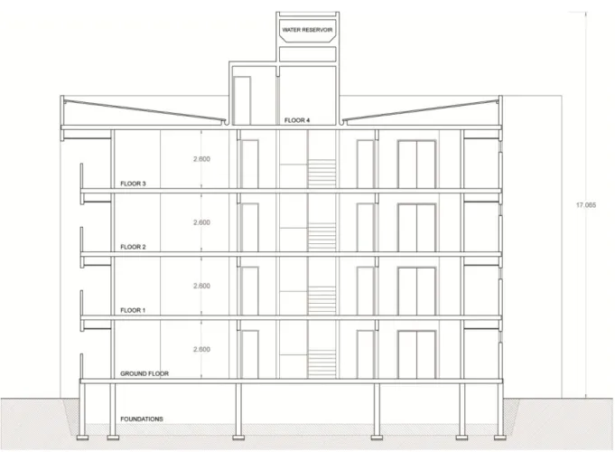
A longitudinal section of the building through the staircase is shown in Figure 14, where the five different levels of the building and the 9750 litres upper water reservoir can be observed. The inter-storey height is 2,60 m and the ground floor is elevated with respect to the outside ground level, meaning that it is necessary to climb four steps in order to access the building. The roof is covered with fibre cement sheets and is not accessible.
Figure 14. Longitudinal section through the staircase (dimensions in metres) 3.2.2 Material and structural survey
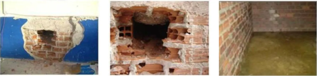
The detailed visual inspection carried out in the foundations, see Figure 15, confirmed continuous reinforced concrete footings, with a width of 500 mm and a height of 150 mm, and unreinforced masonry walls. The masonry walls are constructed with the previously discussed masonry units of 90 x 190 x 190 mm3 with 8 holes positioned horizontally. They lay on their largest dimension, 190 mm, and the average thickness of the mortar bed joints is 30 mm. The external mortar rendering has a variable thickness between 40 and 50 mm and can be easily removed, indicating low mechanical strength. No internal rendering is present. Altogether, the masonry walls are around 230 mm thick. The depth of the ground water table is 0,75 m and, therefore, a significant part of the foundations is in direct contact with water. As there is no waterproofing, the first layers of the masonry walls are permanently saturated. Moreover, there is no sewage collector in the building and the water is contaminated, which may result in accelerated degradation of the mechanical properties of the blocks (de Oliveira, 2009). Chemical analyses of the water were conducted and the sulphate content of the samples was classified as low to moderate, indicating low aggressiveness.
A soil investigation was also carried out, consisting of a chemical analysis of the soil and standard penetration tests (SPT) conducted in several different locations within the residential complex area. The chemical analysis showed an alkaline reaction of the soil, according to the laboratory, as a result
of the water contamination coming from the existing septic tank nearby. Still, the aggressiveness of the soil was rated as low. Regarding the SPT, up to a depth of 3 m, the soil was identified as poor quality soil composed of loose rubble fragments, predominantly alluvial deposits carried out by rivers and greatly influenced by the tidal regime, and medium to fine sand of dark grey colour. Its load bearing capacity was estimated at 100 kPa and therefore, the poor quality of the initial layers of the soil where the foundations settles was confirmed.
Figure 15. Visual inspection of the foundations: (left) opening in the foundations masonry walls with a concrete
tie-beam on top of the wall; (middle) masonry units positioned horizontally and laying on the largest dimension; (right) internal view of the foundation walls, partially filled with earth: caixão vazio
The structural unreinforced masonry walls above ground are constructed with the same masonry units used in the foundations but lying on their smallest dimension, 90 mm. The thickness of the mortar bed joints varies between 20 and 30 mm, the external mortar rendering can reach up to 60 mm and the internal mortar rendering varies between 20 and 25 mm. Therefore, the overall thickness of the walls varies between 130 and 150 mm, see Figure 16.
Floor slabs are ribbed pre-cast concrete consisting of prestressed concrete joists and hollow concrete tiles. There is a cast in situ concrete compression layer of 50 mm and the overall thickness of the slab is 200 mm. The spacing between joists is 450 mm and they are placed covering the smallest span between walls. The presence of reinforced concrete tie-beams at each floor level was confirmed. Figure 17 shows the visual inspection of the floor slabs.
Figure 16. Visual inspection of the building above ground: (left) external walls thickness; (middle) internal wall
thickness; (right) external wall thickness, note that at some door openings, a different arrangement of the bricks can be observed with the holes positioned vertically
Figure 17. Visual inspection of floor slabs: (left) distance between joists; (middle) joists and concrete hollow tiles
composing the floor slab; (right) floor slabs are supported by reinforced concrete tie-beams at the top of each wall
As a conclusion, Figure 18 shows a building axonometric view and Figure 19 shows a construction detail from the foundations to the ground floor, drawn based on the collected data during the visual inspection. Additionally, the visual inspection revealed scattered cracks in the ground floor and a recent intervention aimed to repair existing cracks, verifying actual structural problems.
3.3 Testing and obtained data
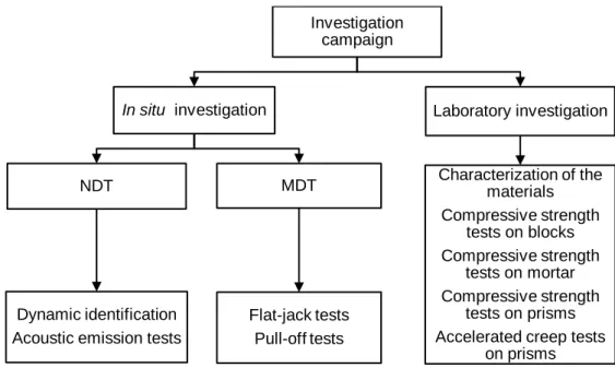
Non-destructive and minor destructive in situ tests were performed to assess the existing damage in the building and to better understand its structural behaviour (de Carvalho, 2010). Additionally, a thorough sampling campaign was conducted and 22 prisms samples were extracted from the building at several different locations for further testing on the laboratory. Most of the parameters later used in the FE model were determined from this extensive experimental research. A description of the most conclusive tests, an itemization of the obtained data and a discussion of the results are provided next. The investigation campaign is summarized in Figure 20.
Figure 20. Investigation campaign carried out in the building 3.3.1 In situ investigation
Dynamic identification
Dynamic testing is a non-destructive technique (NDT) proven to be effective to experimentally measure parameters related to the global structural behaviour. The dynamic properties of the building (frequency, damping and mode shapes) were studied under ambient vibration and later used to validate the FE model.
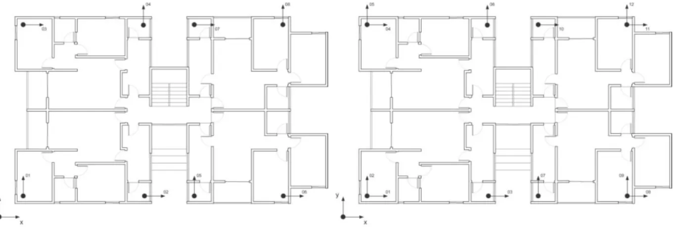
The data acquisition system consisted of several piezoelectric accelerometers and one acquisition unit. The sensors were located in the three upper floors in the two orthogonal directions within the horizontal plane of the structure (Figure 21), in order to capture the bending and torsion modes. Three different set-ups were conducted and measurements were performed with an acquisition frequency of 200 Hz. The environmental conditions were also monitored during the test: the temperature varied between 23,7ºC and 28,0 ºC; and the relative humidity between 60,9% and 87,8%. Since no abrupt changes were measured, it was assumed that the dynamic response of the structure was not affected by the environmental parameters.
Investigation campaign
In situ investigation
NDT
Dynamic identification Acoustic emission tests
MDT Flat-jack tests Pull-off tests Laboratory investigation Characterization of the materials Compressive strength tests on blocks Compressive strength tests on mortar Compressive strength tests on prisms Accelerated creep tests
The modal identification method used was the Stochastic Subspace Identification (SSI), de Carvalho (2010). Table 5 shows the results of the experimental dynamic identification, with seven frequencies identified in the range from 4 to 7,5 Hz. The global dynamic response of the building is influenced by the central staircase, which is stiffer because of the material used. The building has a tendency to rotate while the central staircase remains almost fixed (Figure 22). Regarding the damping coefficient, an average value close to 2,7% was found.
Figure 21. Location of the sensors at: (left) first and second floor; (right) third floor Table 5. Mode frequencies and damping ratios obtained through dynamic testing
Mode Frequency (Hz) Damping (%) Type
1 4,06 2,76 Bending in y 2 4,31 3,78 Bending in x 3 4,88 1,67 Bending in x 4 5,42 3,27 Torsion 5 6,38 2,05 Torsion 6 6,82 2,33 Torsion
7 7,50 3,01 Bending and torsion
Mode 1 – 4,06 Hz Mode 2 – 4,31 Hz Mode 3 – 4,88 Hz Mode 4 – 5,42 Hz
Flat-jack tests
Single flat-jack tests were conducted in order to determine the state of stress of the wall and double flat-jack tests were conducted in order to determine the deformability characteristics of the masonry, i.e. the stress-strain behaviour. Two single flat-jack tests were carried out on walls in the ground floor where the state of stress was suspected to be very high, and one double flat-jack test was carried out in the second floor. It is noted that the reliability of the results is limited due to several difficulties that arose during the tests due to the cutting operation and the poor quality of the blocks.
Regarding the two single flat-jack tests, the cut was made in the horizontal joints at a height of one metre and had the same dimensions of the flat-jack: 800 x 400 mm2. Figure 23 shows the two set-ups, where it is noted that the rendering surrounding the test area was removed in the second test, as well as the mortar of the horizontal joint. In the second test, steel plates were used to adjust the flat-jack and try to obtain more reliable results than those obtained in the first test by applying a more uniform distribution of stresses along the flat-jack. However, the recovery of the slot displacements was not reached in all the measuring points in both cases and according to the standards, tests in which the limits of the allowable average deviation from the original gage length are exceeded shall be considered invalid (ASTM C1196, 2004). Still, the normal stress measured was 0,31 MPa in test 1 and 0,40 MPa in test 2.
Figure 23. Single flat-jack tests set-up: (left) test 1 set-up; (middle) test 2 set-up; (right) test 2 slot
Concerning the double flat-jack test, steel plates were also used aimed again at achieving a more uniform distribution of stresses along the flat-jack. The cuts were made in the horizontal joints but the mortar was not entirely removed. The distance between flat-jacks was 660 mm. The stress-strain behaviour was obtained and the modulus of elasticity was estimated at 800 MPa. However, after the appearance of cracks close to the upper slot, the continuation of the test was impossible and thus, its reliability is also questionable. The lack of the necessary stresses above the jack in the testing place, as there are only two floors above it, may be the reason for the early cracking of the masonry.
Pull-off tests
The mortar rendering proved to have a significant influence on the mechanical behaviour of the masonry and therefore, pull-off tests were performed to determine the tensile bond strength. This mechanical property is mainly affected by the mortar characteristics, the substrate surface and the application technique.
The pull-off test involved the application of a direct tensile load to a delimited area through the use of a glued metal disk with a pull pin. A loading device applies the load to the pin at a constant rate. Five tests were conducted in each floor, in both internal and external walls on the ground floor, and only in the internal walls on the other floors. The foundation masonry walls were not tested because the rendering was easily removed with the help of a sharp tool or even with the hand, indicating already a low mechanical strength. The Brazilian norm (NBR 13528, 1995) establishes the minimum tensile bond strength at 0,3 MPa. Table 6 shows the results obtained and confirm that they do not meet this requirement, meaning that the bond is too weak. All failure modes consisted of failure in the bond-substrate interface.
Table 6. Average tensile bond strength in each floor
Floor Average tensile bond
strength (MPa) Variation (%) 0 (external walls) 0,24 14,0 0 (internal walls) 0,15 27,4 1 0,14 9,2 2 0,23 11,8 3 0,21 23,0
Acoustic emission tests
The acoustic emission technique is a damage detection method that can be applied in masonry buildings and permits to estimate the amount of energy released during crack propagation and to obtain information on the criticality of the ongoing process (Carpinteri, 2006). Diffuse damaging is characteristically produced by compression and tests were performed on the ground floor aimed precisely at detecting the accumulated damage in a location where the stress was suspected to be very high and there were visible cracks. Results obtained showed active accumulated damage but they are not conclusive because the duration of the tests was too short to determine accurately the quantity and evolution of this damage.
The previously discussed flat-jack tests were also monitored using the acoustic emission technique aiming at observing the evolution of the damage and the propagation of cracks on the masonry tested to failure by these tests. The results detected a significant increase of the damage when the applied stress level exceeded the original state of stress, confirming the adequacy of the method to evaluate the safety of these buildings using permanent long term monitoring. The best results were obtained when the AE sensors were fixed directly on the block and not on the rendering. Further research was encouraged.
3.3.2 Laboratory investigation
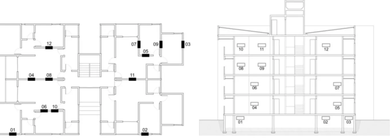
The laboratory investigation aimed at defining the characteristics of the materials and the structure itself. During the sampling campaign, a total of 22 prisms samples were extracted from the building at different locations, from the foundations to the third floor. 10 prisms were tested in the laboratory of the University of Minho and 12 in the laboratory of the SENAI-PE (Serviço Nacional de Aprendizagem Industrial de Pernambuco), in Brazil. Figure 24 shows the location of these last 12 prisms extracted from the building.
Figure 24. Location of the prisms extracted from the building: (left) plan; (right) section
Testing of blocks
Hollow clay blocks of similar characteristics to those used in the box-buildings were purchased directly from the Brazilian industry for testing. Initial rate of absorption tests, water absorption tests and compressive strength tests were performed on them. The dimensions of the blocks were 190 x 190 x 90 mm3 and they did not present defects such as flaws, cracks, deformations or significant variations in geometry or colour.
Water absorption tests were also performed on blocks extracted directly from the building. However, these blocks could not be used for the other tests because the rendering was much adhered to the substrate. The water absorption measured in the purchased blocks was 13,5% and the water absorption measured in the blocs extracted from the building was 15,6%. Both values were among the limits recommended by the standards, between 8% and 22%. Regarding the initial rate of absorption (IRA) of the units at the time they are laid, the standard recommendations are at the level of approximately 30 g/min per 193,55 cm2. The initial rate of absorption of the blocks was 43 g/min per 193,55 cm2, higher than the recommended value.
Monotonic uniaxial compressive tests were then performed on six purchased blocks to have a first indication of the compressive strength of the material. From these tests, the peak stress and the elasticity modulus were obtained. Since some of the blocks are expected to be saturated in the building, three blocks were immersed in water prior to testing and an important distinction was made
between saturated and non-saturated condition. This distinction will be done in the rest of the laboratory tests carried out. Blocks were laid on their largest dimension and Table 7 shows the results obtained, which are remarkably low and, as expected, even lower for the saturated blocks.
Table 7. Results of compressive tests
Compressive strength (MPa) Modulus of elasticity (MPa)
1 2 3 Av. COV 1 2 3 Av. COV
Saturated blocks 0,55 0,92 1,49 0,97 48% 74,3 70,9 189,2 111,2 61%
Non-saturated blocks 2,08 1,19 1,26 1,51 33% 152,7 161,8 122,8 147,8 14%
Short-term creep tests
Short-term creep tests were carried out on newly constructed samples using the above blocks. The masonry specimens were made by constructing small prisms of two blocks layered one on top of each other and lying horizontally on their largest dimension. A mortar joint thickness of 25 mm was used. The mortar included cement, hydrated lime and sand, with the composition indicated in Table 8. Compressive tests and bending tests were performed on mortar samples and the results are presented on Table 9. For these tests, the distinction between saturated and non-saturated condition was also made and thus, some samples were immersed in water prior to testing. Tests were performed on prism-shaped specimens (40 x 40 x 80 mm3) and on cylinder specimens of 50 mm diameter and 100 mm height.
Table 8. Mortar composition
Material unit weight (kg/dm3) Volume composition w/c ratio
Cement CEM II/B-L 32,5 N Hydrated lime Sand
1,08 0,76 1,45 1:1:6 1,7
Table 9. Results of compressive tests and bending tests on mortar specimens.
Prism-shaped specimens Cylinder specimens
Compressive strength (MPa) Flexural strength (MPa) Compressive strength (MPa) Modulus of elasticity (MPa) Saturated 3,86 (5) 1,17 (5) 3,00 (19) 5570 (3) Non-saturated 6,29 (11) 2,30 (2) 3,82 (12) 6590 (0,5)
Legend: average values from three specimens (coefficient of variation in percentage)
Monotonic uniaxial compression tests were performed on the prisms in order to provide a reference value of the compressive strength of the masonry. This value was used subsequently also to estimate the load increments to be applied during accelerated creep tests. For this test, six specimens were
constructed and three of them were immersed in water for 28 days. The stress-strain behaviour was registered and the compressive strength and Young’s modulus calculated. The results are shown in Table 10 and the failure mode consisted of failure of the block. Here, Av. means average and COV means coefficient of variation. One of the saturated prisms was lost in the testing preparation.
Table 10. Results of compressive tests on masonry specimens
Compressive strength (MPa) Modulus of elasticity (MPa)
1 2 3 Av. COV 1 2 3 Av. COV
Saturated prisms 1,07 0,62 - 0,84 38% 355,6 188,3 - 272,0 43%
Non-saturated prisms 1,17 1,50 1,15 1,27 15% 377,6 763,3 913,4 684,8 40%
The short-term creep tests were then performed under laboratory conditions of T=24ºC and RH=60%. The load path used started at 40% of the previously determined mean compressive strength. Load increments of 10% of the mean compressive strength were then applied, kept constant during 5-8 hours, and finally increased until collapse. Six prisms were again tested: being three saturated and three non-saturated. Both the loading path and the strain-time diagrams were obtained and from them, the final creep strain was calculated. The final creep coefficient and long-term modulus were computed according to the equations provided by Eurocode 6 (2005):
𝜙∞ = 𝜀𝑐∞ 𝜀𝑒𝑙 (1) 𝐸𝑙𝑜𝑛𝑔 𝑡𝑒𝑟𝑚 = 𝐸 1 + 𝜙∞ (2)
The results are presented in Table 11. The final creep coefficient for the saturated masonry remained in the range established by Eurocode 6 (2005), which is between 0,5-1,5 for clay units, but the obtained value for the non-saturated masonry is considerably higher.
Table 11. Final creep coefficient and long-term modulus
Compressive strength (MPa) Modulus of elasticity (MPa) Elastic strain (𝜀𝑒𝑙) Final creep strain (𝜀𝑐∞) Final creep coefficient (𝜙∞) Long-term modulus (MPa) Saturated 1,07 272,0 0,0039 0,0041 1,04 133,4 Non-sat. 1,27 684,8 0,0019 0,0038 2,05 224,5
Testing of the mortar extracted from the building
The characterization of the mortar extracted using the pull-off tests performed in situ on the building was carried out and its composition determined (Table 12). Then, compressive strength tests were performed on six specimens, three of which were saturated. The results are shown on Table 13.
Table 12. Mortar composition
Location of the mortar Binding agent (g) Aggregate (g) Unit weight composition
Foundations 22,84 92,10 1:4,03
Ground floor 32,83 79,80 1:2,43
1st, 2nd and 3rd floor 24,34 87,84 1:3,61
Table 13. Results of compressive tests on mortar specimens
Compressive strength (MPa)
1 2 3 Av. COV
Saturated 3,54 2,90 3,23 3,22 10%
Non-saturated 6,07 4,36 5,37 5,23 16%
Testing of masonry prisms extracted from the building at the University of Minho
Only six out of the ten prisms collected could be tested in the laboratory of the University of Minho. Three of them were immersed in water for 28 days before testing. The dimensions of the prisms were remarkably variable and Table 14 presents their geometrical characteristics. The average thickness of the mortar bed joint was assumed as 27 mm.
Table 14. Geometrical characteristics of the prisms. Note great variation in the values of the rendering thickness.
Thickness Prism Height (mm) Width (mm) Rendering a (mm) Block (mm) Rendering b (mm) Total (mm) Saturated 1 670,00 310,00 30,50 89,00 30,50 150,00 2 664,60 310,00 14,90 90,50 25,30 130,20 3 666,50 300,00 19,50 91,00 29,50 140,00 Average 667,03 306,67 21,63 90,00 28,43 140,10 COV 0,4% 2% 37% 1% 10% 7% Non-sat. 1 665,00 300,00 20,00 89,90 34,50 144,40 2 675,00 315,00 20,00 90,00 30,00 140,00 3 667,00 300,00 35,50 89,90 40,50 165,00 Average 669,00 305,00 25,17 89,63 35,00 149,80 COV 0,8% 3% 36% 1% 15% 9%
Monotonic compressive tests were performed on the prisms to have an indication of the compressive behaviour of masonry. From these tests, the strength and the elasticity modulus were obtained, whose values are shown on Table 15. The results from these tests will later be used in the finite element model. The detachment of the rendering occurs after reaching values close to the ultimate compressive strength, confirming its influence on the compressive behaviour. Figure 25 shows the failure modes of the prisms and the detachment of the rendering.
Table 15. Results of compressive tests on prisms tested at the University of Minho
Compressive strength (MPa) Modulus of elasticity (MPa)
1 2 3 Av. COV 1 2 3 Av. COV
Saturated prisms 1,25 1,82 1,69 1,59 19% 1034,0 1036,0 964,5 1168,2 25%
Non-saturated prisms 2,69 2,64 2,23 2,52 10% 2558,0 2973,0 4392,0 3307,0 29%
Figure 25. Failure modes of the prisms
Testing of masonry prisms extracted from the building at SENAI-PE
Twelve prisms were tested at the laboratory of the SENAI-PE. Monotonic compressive tests were also performed on them and from these tests the compressive strength was obtained. Dimensions of the prisms were again considerably variable. Table 16 presents the geometrical characteristics of the prisms and the results of the compressive strength tests. Results are divided according to the location where the prisms were extracted. The failure mode observed in the prisms was the same as in the prisms tested at the University of Minho, collapse of the prisms occurred right after the detachment of the rendering (Figure 26).