A New Strategy To Control The Seismic
Response Of Buildings: The Base
Dissipation
Luigi Petti #1, Alessio Lodato #2, Bruno Palazzo #3
#
Department of Civil Engineering, University of Salerno, Italy
Abstract— The innovative control strategy of seismic response of buildings “Base Dissipation” (BD) is herein described and analysed. The new control strategy leads to dissipate seismic energy at base of a building through the decoupling of the motion of the superstructure from the soil one through an appropriate damping hinge interface.
To investigate the proposed strategy, a non-classical damped system is analyzed by an innovative mathematical formulation in the state space by considering a 2DOF system, being the superstructure described by the first mode shape. Modal and numerical analyses lead to identifying optimal design parameters and allowing for preliminary investigation of the robustness of the new BD control strategy.
Keyword- Base Dissipation, Seismic Control, Non Classical Damping
I. INTRODUCTION
Current seismic design philosophies provide satisfying structural performances based on serviceable and damage targets by considering the seismic hazard and the building importance [15], [2]. Performance Based Design (PBD) is currently being implemented by the Capacity Design Method (CDM) in order to verify the performance levels.
For the case of Ultimate Limit States (ULS), the goal is achieved by ensuring adequate dissipative capacity through ductile mechanisms. However, although several buildings performed well during last seismic events according to the design targets, the extended damages were not always sustainable for public general [11]. The innovative seismic protection strategies lead to a high repair cost saving, shifting new technical codes towards a more restrictive damage control level target.
Fig.1 PED strategy applications
A first formulation of damping mechanism within the context of structural engineering was made by [6], who classified damping in three main typologies: rate-dependency, quadratic/non quadratic, and recoverable/non recoverable damping. His definition, although represents the fundamental essence of damping concept, has not yet been adapted in the design of earthquake protective systems.
A review of the current practice and recent developments in the application of passive energy dissipation systems for seismic protection of structures is provided in [17] and [20].
Several research have been carried out in [19] regarding the control strategy type (a) on the magnification of effects of installation of dampers in a framed structure. In the case of control strategies type (c), some research has been carried out in [18] showing that prestressed concrete framing system with unbonded post-tensioned reinforcement and bonded bar reinforcement had structural performances equal or superior to that of a conventional cast-in-place moment resisting frame. The experimental tests present in [16] on a five story precast concrete building characterized by four different ductile structural frame systems in one direction of response and a jointed structural wall system in the orthogonal direction confirmed the low damage and low residual drift expected of the building. More recently, post-tensioned rocking wall systems equipped with externally mounted damping devices have been tested on shake-table at the University of Canterbury [8]. Results show that maximum displacements and material strains were well controlled and within acceptable bounds, and residual deformations were minimal due to the re-centering contribution from the post-tensioned tendons. Further advances in the development of high-performance seismic-resistant bridge piers have been achieved through the experimental validation of unbonded post-tensioned bridge piers with external, fully replaceable, mild steel hysteretic dissipaters [9], [11].
To fulfill the compelling requirements of cost effectiveness and high seismic-performance, major efforts have been made towards the development of damage-control technologies, in integration of the more common and renown base isolation and energy dissipation options by implementing new structural systems, control strategy type (d). An example of this control strategy can be found in [4] where the passive control performance that can be achieved through a visco-elastic damper connecting two adjacent free-standing structures have been investigated.
Fig.2 Base Isolation and Base Damping Conception.
One possible way to realize the BD strategy is to use an appropriate arrangement of damping devices at the base between the foundation and superstructure as showed in figure 3.
Fig.3 BD application.
The rocking response in the systems leads to dissipating energy at base, preserving structural elements from damage.
To investigate the proposed control strategy, the superstructure is herein modeled through the contribution of the first mode shape and the base interface is described by an equivalent linear–viscous behaviour. In this case, the system results non-classically damped so the dynamic problem is faced by using an innovative formulation in the state-space [7] to decouple modal shapes also considering the second-order effects. The problem is completely described through analysis of state matrix which allows the dynamic properties of the controlled system in terms of mode shapes, vibration periods and participation factors at varying of the geometric degrading effects to be obtained.
Results of linear dynamic analysis, in terms of normalized spectra of energy, displacements and accelerations, show the possibility to optimally design the overall system reducing the seismic response of the superstructure.
II. DYNAMICAL MODEL
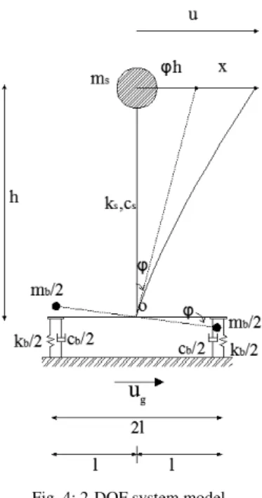
A 2DOF system is herein considered to investigate the proposed strategy, where the superstructure is modeled through the contribution of the first mode shape and the base is supported by viscoelastic dampers and elastic springs (Fig.4). In particular, the superstructure dynamical model is described by equivalent height h, lumped mass ms, lateral stiffness ks and linear viscous damping cs
2 /
b
m
. The base is described by the semi length l, the lumped masses , the vertical stiffness kb/2, and the linear viscous damping cb/2.
When the structure is subjected to a seismic excitation ug(t), the mass ms
h
ϕ
Fig. 4: 2-DOF system model.
The differential equations governing the small-amplitude motion of the system of Fig. 1, taking into account the first order theory instability effects, can be written as:
g s
s s
s x x h u
h
x+ϕ +2ξ ω +ω2(1−β) −βω2ϕ =− (1)
1 2
1 2
2
2+ + + =− +
+ r u h h r x
h b b g
bϕ γ
ω ϕ ω ξ γ
ϕ (2)
where: ωs = ks /ms and ξs =cs/c0 are respectively the natural frequency and damping factor of the
superstructure considered fixed at base;
s b b b m r m r k + = 2 2
ω and
) ( 2 2 2 s b b b b m r m r c + = ω
ξ the vibration frequency and the damping factor of the system considering the superstructure infinitely rigid; ε =ωb/ωs the degree of
coupling of the system; γ =mb /ms the mass ratio; r=l/h the slenderness-ratio parameter;
2
/h s g ω β = the instability factor.
The equations (1-2) can be arranged in the following matrix notation: ) ( ) ( ) ( )
(t Cv t Kv t ru t v
M + + =− g (3)
where v=
{
x,ϕh}
is the relative displacement vector and r={ }
1,0T the influence vector; M , K and Crepresent, respectively, the mass, the stiffness and the damping matrices:
+ = s b s s s m r m m m m
M 2
− − = 2
0 k r h g m h g m k K b s s s = 2 0 0 r c c C b s (4)
The Equation (3), by considering the “state vector”
{ }
T
v , v
x= , can be rewritten in the following first order differential form:
g x
x =A⋅ +B⋅u (5) where A and B, respectively called “dynamic matrix” and “input system distribution matrix”, are:
− − = − − C M K M I
A 01 1
− = r B 0
the matrix A [14], in our case haves 2 pairs of complex eigenvalues λj and eigenvectors ϕR,j related by the
following relationship: j R, j j R,
ϕ
ϕ
=λAs known, the eigenvalues have the following form: 2 j j j j
j=−ωβ ± ω 1−β
λ i
(7)
where ωj and βj are respectively the frequency and the damping factor describing the j-th modal shape. As
shown by [5], these eigenvalues are equal to the ones of the transposed dynamic matrix:
L L T
φ
=λφ
A (8)
The eigenvectors obtained by the Eq. (6) are called right eigenvectors (
ϕ
R,j), while those obtained by the Eq.(8) are called, instead, left eigenvectors (
ϕ
L,j). The left and right eigenvectors satisfy the biorthogonalityproperty [5]:
j i if 0 i R, T j
L,ϕ = ≠
ϕ (9)
To decouple the Eq. (5), it is possible to assume that the solution is described as a linear combination of the mode shapes:
∑
= j j j R,q ϕx (10)
where qj, a time scalar function, is the j-th modal coordinate. The following decoupled dynamic equation can
be written: g T L R T
L q u
q =φ Aφ +φ B (11)
g
u B q A q = +
(12)
The dynamic matrix A of the Eq. (12) is now a diagonal matrix whose terms, considering the (12), represent the eigenvalues of the Eq. (5). The matrix B is, instead, the input signal distribution vector whose components
j
L represent the modal participation factors associated with each mode shape:
B T j L, j
L =ϕ (13)
III.ANALYSIS OF DYNAMICAL BEHAVIOUR
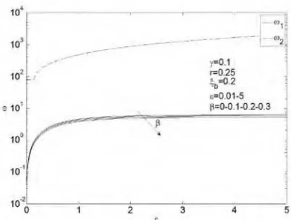
Modal analysis have been carried out by varying the degree of coupling (ε= 0.00÷5.00) and the instability factor (β = 0.00 – 0.10 – 0.20 – 0.30) to analyze the dynamical behavior, having considered the following parameters: r=0.25, γ=0.10, ξs=0.05, ξb = 0.20.
Figures 5-6 plots respectively the frequencies and damping factors associated with the two mode shapes. The analysis of the results shows, as expected, that both the frequencies increase by increasing the degree of coupling ε, while only the first modal shape frequency decreases by increasing the instability factor β . Moreover, by increasing the degree of coupling ε in the range [0.00,1.50], the damping of the first mode shape decreases from the value associated to the base to the one describing the superstructure. For ε less than 1, the damping factor decreases by increasing β , increases for ε greater than 1. The second mode shape becomes overdamped for value of ε greater than 0.15.
Figures 7 and 8 show the poles of the system in the complex plain associated with both the modal shapes. The results show that the first modal shape present minimum real values, maximum damped conditions, for ε equal to 0.65. Moreover, by increasing β , the damping capacities decrease. The results obtained for the second modal shape confirm that these modes are overdamped for ε greater than 0.15.
Figures 9 and 10 represent the modal contribution to the displacements by considering participation factors (φI,1L1,φII,1L1) associated with the first modal shape and the ones (φI,2L2,φII,2L2) associated with the second
Fig. 5. Frequencies associated with the first and second modal shapes, by varying β.
Fig. 6. Damping factors associated with the first and second modal shapes, by varying β .
Fig. 7. System poles associated with the first modal shape, by varying β .
Fig. 9. Modules of the products between the modal shapes and the modal participation factors associated with the first mode, by varying β .
Fig. 10. Modules of the products between the modal shapes and the modal participation factors associated with the second mode, by varying β.
Considering the dynamical response of the system, it is possible to make the following main considerations for the considered mechanical parameters: the maximum damped conditions are reached when the degree of coupling (ε) is equal to 0.65; values of ε less than 0.65 lead to a minimum overall response; ε equal to 0.15 leads to resonance phenomena on the second shape mode; the geometrical degrading effects (β ) lead to a considerable worsening of the overall dynamical response.
IV.ANALYSIS OF SEISMIC BEHAVIOUR
To clarify the behaviour of the proposed control strategy, seismic analysis have been carried out considering three selected recorded earthquakes: Northridge 1994, E-W component, Tarzana Cedar Nursey station; L’Aquila 2009, N-S component, L’Aquila Parking station; Imperial Valley 1979, E-W component, El Centro n°8 station. Figures 11-12 plot pseudo-accelerations and displacements spectra for the considered seismic events, highlighting the strong differences between the events in terms of energy contents.
Fig.12. Displacements spectra.
The main results of the linear dynamic analysis in terms of normalized spectra of viscous energy, displacements and accelerations are reported below, considering the same set of parameters used for the modal analysis.
Fig.13. Normalized viscous energy spectra – Northridge event.
Fig.14. Normalized viscous energy spectra – L’Aquila event.
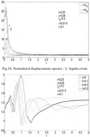
Fig.16. Normalized displacements spectra – L’Aquila event.
Fig.17. Normalized absolute accelerations spectra – Northridge event.
Fig.18. Normalized absolute accelerations spectra – L’Aquila event.
Figures 13 and 14 show normalized viscous energy spectra for considered seismic events. In particular, the superstructure (Eξ), the base (Eξ,b) and the total viscous energy (Eξ,tot) spectral values have been normalized
respectful to those obtained when the superstructure is considered fixed at base. For both cases, the superstructure energy response is less than the one of the fixed base system when ε ∈[0.00,1.00] and generally increases as greater is β . Furthermore the base energy response reaches the highest values in the same range and decreases as greater is β . For high values of the degree of coupling the energy response is near the one of the fixed base case.
Figures 15 and 16 show normalized displacements spectra in terms of superstructure relative displacement (x) and total relative displacement (u). For both cases, the superstructure relative displacements are lower in the range of ε ∈[0.00,1.00] and generally increase as greater is β .Furthermore, the total superstructure displacement decreases as increasing ε, leading to the fixed base displacements values.
Figure 17 and 18 show the response in terms of absolute accelerations for considered seismic events. In particular, the absolute acceleration (uabs) has been normalized respectful to the one obtained when the
Fig.19. Normalized viscous energy spectra – Imperial Valley event.
Fig.20. Normalized displacements spectra – Imperial Valley event.
To have a clearer sight of the influence of geometric degrading effects on seismic response of the proposed system, normalized displacement components, absolute accelerations and energy rates respect those of fixed base system are plotted considering a fixed degree of coupling (ε=0.50) for the Northridge 1994 event (Figs. 21-24). Results confirm those obtained previously.
Figures 25 and 26 show respectively normalized spectra of displacements and absolute accelerations at varying of added damping factor ξb. Results show that response has larger decrease up to values of 20% of base
damping factor and becomes less significative for higher values.
Fig.22. Normalized maximum absolute accelerations at varying of β .
Fig.23. Normalized maximum superstructure energy rates at varying of β .
Fig.24. Normalized maximum base energy rates at varying of β .
Fig.26. Normalized absolute accelerations spectra – Imperial Valley event.
V. CONCLUSIONS
The paper introduces the new seismic control strategy of “Base Dissipation” (BD) of structure which provide a damping interface between the soil and the super-structure capable to dissipate seismic energy trough a particular base rotational kinematic mechanism. The dynamic problem is faced by a new formulation in the state space, that goes over the limits of classical modal analysis in earthquake engineering, allowing to explicitly analyse the dynamic behaviour of non-classically damped systems.
Modal and numerical seismic analysis have been carried out by considering an equivalent 2DOF system to investigate the dynamical properties and the robustness of the proposed new control strategy.
The research and the obtained numerical results lead to the following main conclusions. The considered mathematical model, describing the strategy in the state space, leads to identify optimal design parameters in terms of degree of coupling and base damping factor, taking into account the geometric degrading effects. The proposed Base Dissipation control strategy, which seems mostly effective in the case of events characterized by high energy content in the low periods range, gives new and fascinating opportunity to favourable regulate the seismic response of buildings by implementing new structural systems.
REFERENCES
[1] Bertero V.V., Uang C.M,. Evaluation of seismic Energy in structures, Earthquake Engineering and Structural Dynamics, 19, 77-90, 1992.
[2] Fajfar P., Krawinkler H., Performance-Based Seismic Design Concepts and Implementation, International Workshop, Bled, Slovenia, 2004.
[3] Farzad N., Kelly J.M., Design of seismic isolated structures – From theory to practice, John Wiley & Sons, Inc., 1999.
[4] Gattulli V., Potenza F., Lepidi M., Damping performance of two simple oscillators coupled by a visco-elastic connection, Journal of Sound and Vibration, 332 6934-6948, 2013.
[5] Hoen C., An Engineering Interpretation of the Complex Eigensolution of Linear Dynamic Systems, IMAC XXIII – Orlando, Florida January 31 – February 3, 2005, USA, 2005.
[6] Lazan, B.J., Damping of Materials and Members in Structural Mechanics, NY: Pergamon Press, 1968.
[7] Liang Z., Lee G.C., Dargush G.F., Song J., Structural Damping - Application in Seismic Response, CRC Press, 2012.
[8] Marriott D., Pampanin S., Bull D., Dynamic Testing of Precast, Post – Tensioned Rocking Wall Systems with Alternative Dissipating Solutions, 2008 NZSEE Conference, 2008.
[9] Marriott D., Pampanin S., Palermo A., Quasi-static and pseudo-dynamic testing of unbonded post-tensioned rocking bridge piers with external replaceable dissipaters, Earthquake Engineering and Structural Dynamics; 38:331-354, 2009.
[10] Palazzo B., Petti L., Aspects of Structural Vibration Passive Control, International Journal of MECCANICA Vol. 32 N.6 Dec.1997. [11] Pampanin. S., Reality-check and Renewed challenges in Earthquake Engineering: Implementing low-damage structural Systems –
from theory to practice, University of Canterbury, Christchurch, New Zealand, 2012.
[12] Petti L., Il Controllo delle Vibrazioni delle Costruzioni Civili- Teoria ed Applicazioni, University of Salerno, 1992-1995.
[13] Petti L., Polichetti F., Analysis of the Dynamic Behaviour of Base Isolated Structures by State-space Formulation, Ingegneria Sismica, No 4., 2012.
[14] Perko L., Differential Equations and Dynamical Systems, Springer-Verlag Berlin and Heidelberg GmbH & Co. K., 1991.
[15] Priestley M.J., Performance Based Seismic Design, 12th World Conference on Earthquake Engineering, Auckland, New Zealand, 2000.
[16] Priestley M.J., Sritharan S., Conley J.R., Pampanin S., Preliminary Results and Conclusions from the PRESS Five-Story Precast Concrete Test Building, PCI Journal, 44(6), 42-67, 1999.
[17] Soong T.T., Spencer B.F. JR, Supplemental energy dissipation: state of the art and state of the practice, Engineering Structures 24 243-259, 2002.
[18] Stanton J., Stone W.C., Cheok G.S., A Hybrid Reinforced Precast Frame for Seismic Regions, PCI Journal, Vol.42, No.2, pp.20-32, 1997.
[19] Sigaher A.N., Constantinou M.C., Scissor-Jack-Damper Energy Dissipation System, Earthquake Spectra: February 2003, Vol. 19, No. 1, pp. 133-158, 2003.
[20] Symans M.D., Charney F.A., Whittaker A.S., Constantinou M.C., Kircher C.A., Johnson M.W., Mcnamara R.J., Energy dissipation systems for seismic applications: Current practice and recent developments, ASCE 10.1061 3-21, 2008.