UNIVERSIDADE FEDERAL DO PAR ´
A
INSTITUTO DE TECNOLOGIA
PROGRAMA DE P ´
OS-GRADUC
¸ ˜
AO EM ENGENHARIA EL ´
ETRICA
FPGA-Based Testbed for Fronthaul Signal Compression: Implementation and Validation
Joary Paulo Wanzeler Fortuna
DM: 16/2017
UFPA / ITEC / PPGEE Campus Universit´ario do Guam´a
UNIVERSIDADE FEDERAL DO PAR ´
A
INSTITUTO DE TECNOLOGIA
PROGRAMA DE P ´
OS-GRADUC
¸ ˜
AO EM ENGENHARIA EL ´
ETRICA
Joary Paulo Wanzeler Fortuna
FPGA-Based Testbed for Fronthaul Signal Compression: Implementation and Validation
DM: 16/2017
UFPA / ITEC / PPGEE Campus Universit´ario do Guam´a
UNIVERSIDADE FEDERAL DO PAR ´
A
INSTITUTO DE TECNOLOGIA
PROGRAMA DE P ´
OS-GRADUC
¸ ˜
AO EM ENGENHARIA EL ´
ETRICA
Joary Paulo Wanzeler Fortuna
FPGA-Based Testbed for Fronthaul Signal Compression: Implementation and Validation
A dissertation submitted to the examination com-mittee in the graduate department of Electrical Engineering at the Federal University of Par´a in partial fulfillment of the requirements for the de-gree of Master of Science in Electrical Engineer-ing with emphasis in Telecommunications.
UFPA / ITEC / PPGEE Campus Universit´ario do Guam´a
iii
FPGA-Based Testbed for Fronthaul Signal Compression: Implementation and Validation
Dissertac¸˜ao de mestrado submetida `a avaliac¸˜ao da banca examinadora aprovada pelo colegiado do Programa de P´os-Graduac¸˜ao em Engenharia El´etrica da Universidade Federal do Par´a e julgada adequada para obtenc¸˜ao do Grau de Mestre em Engenharia El´etrica na ´area de Telecomunicac¸˜oes.
Aprovada em / /
Aldebaro Barreto da Rocha Klautau J´unior
ADVISER
Leonardo Lira Ramalho
CO-ADVISER
Jo˜ao Cris´ostomo Weyl Albuquerque Costa
MEMBER OF EXAMINATION COMISSION
Daniel Cardoso de Souza
iv
Roberto Menezes Rodrigues
MEMBER OF EXAMINATION COMISSION
Evaldo Gonc¸alves Pelaes
Acknowledgments
The author would like to thanks firstly God for helping in the difficult moments. Then, his family for support and patience. Also, to his advisor and co-adivisor for all the hard work invested in this dissertation. Finally, thank to all the work team of LASSE for all the acquired experience.
vi
”They did not know it was impossible so they did it”
Acronyms
ADC Analog to Digital Converter AWG Arbitrary Waveform Generator AXI Advanced Extensible Interface BBU Base Band Unit
BER Bit Error Rate BF Basic Frame
BRAM Block Random Access Memory BS Base Station
BW Bandwidth
CAPEX Capital Expenditures
CDMA Code Division Multiple Access CM Configuration Management CP Cyclic Prefix
CPRI Common Public Radio Interface CPU Central Processing Unit
C-RS Cell-Specific Reference Signal CW Control Word
DAC Digital to Analog Converter
DASH Dynamic Adaptive Streaming over HTTP DDR Double Data Rate
DFT Discrete Fourier Transform
viii
DU Digital Unit
EDGE Enhanced Data Rates for GSM Evolution EVM Error Vector Magnitude
FFT Fast Fourier Transform FIFO First In First Out
FIR Finite Impulse Response
FPGA Field Programmable Gate Array FSM Finite State Machine
FTP File Transfer Protocol
GNSS Global Navigation Satellite System GPS Global Positioning System
GSM Global System for Mobile Communications HARQ Hybrid Automatic Repeat Request
HDLC High-Level Data Link Control
IEEE Institute of Electrical and Electronics Engineers IFFT Inverse Fast Fourier Transform
IP Internet Protocol
LPC Linear Predictive Coding ISG Industry Specification Group
ITU International Telecommunications Union JTAG Joint Test Action Group
LSB Least Significant Bit LTE Long Term Evolution LUT Lookup table
MAC Media Access Control Layer MIMO Multiple Input Multiple Output MMCM Mixed-Mode Clock Manager MSB Most Significant Bit
NGFI Next Generation Fronthaul Interface NQ Non-Quantized
OAM Operation and Maintenance
ix
OPEX Operation Expenditures
ORI Open Radio Equipment Interface PBCH Physical Broadcast Channel
PCFICH Physical Control Format Indicator Channel PDCCH Physical Downlink Control Channel PDSCH Physical Downlink Shared Channel PDV Packet Delay Variation
PHICH Physical Hybrid-ARQ Indicator Channel PHY Physical Layer
PLL Phase Locked Loop PTP Precision Time Protocol
PUSQH Predictive Uniform Scalar Quantization with Huffman QAM Quadrature Amplitude Modulation
RAN Radio Access Network RAT Radio Access Technology RB Resource Block
RE Resource Element
REC Radio Equipment Controller RF Radio Frequency
RRU Remote Radio Unit RTC Real-Time Clock RTT Round Trip Time RU Radio Unit
SMA SubMiniature Version-A Cable TCP Transmission Control Protocol TOC Total Ownership Cost
TSN Time Sensitive Network
UART Universal Asynchronous Receiver/Transmitter UFPA Federal University of Par´a
x
WCDMA Wideband Code Division Multiple Access WDM Wavelength-Division Multiplexing
Symbols
NAxC Number of antennas carried over the Fronthaul
IQb Number of bits per complex IQ sample
Fs Sample rate of the LTE signal transported over the Fronthaul
RCP RI CPRI bit-rate used on the Fronthaul configuration
NR CPRI line-rate option used on the Fronthaul configuration
OV Overhead generated by the Ethernet header and fronthaul Metadata on the CPRI stream Hs Number of bits allocated for the headers on each Ethernet frame
NBF Number of CPRI Basic Frames transported on each Ethernet frame
J Maximum accumulation jitter created by Basic Frame accumulation T1,k Timestamp acquired by PTP at the transmission of SYNC message
T2,k Timestamp acquired by PTP at the reception of SYNC message
T3,k Timestamp acquired by PTP at the transmission of DELAY REQ message
T4,k Timestamp acquired by PTP at the reception of DELAY REQ message
y Calculated frequency offset error by PTP x Calculated time offset error by PTP Tsm One way delay from PTP slave to master
Tms One way delay from PTP master to slave
ˆ
List of Figures
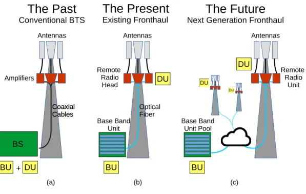
2.1 The fronthaul evolution. . . 5
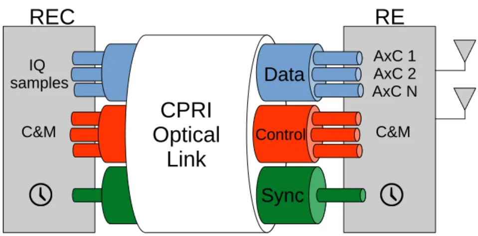
2.2 Information carried in CPRI link. . . 8
2.3 CPRI Basic Frame internal structure [1]. . . 10
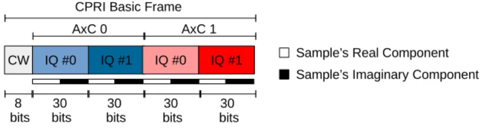
2.4 Example of CPRI Basic Frame carrying two signals with 30 bits per IQ sample. 10 2.5 CPRI naming convention and frame structure [1]. . . 11
2.6 Overview of OBSAI building blocks [2]. . . 12
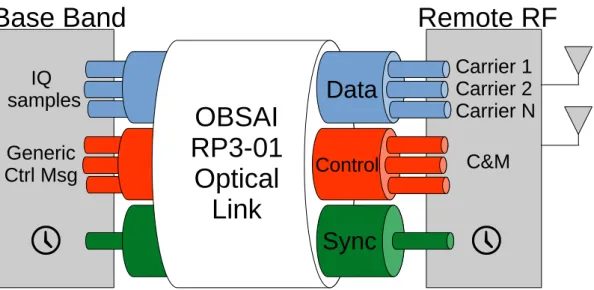
2.7 Information carried by OBSAI RP3 link. . . 13
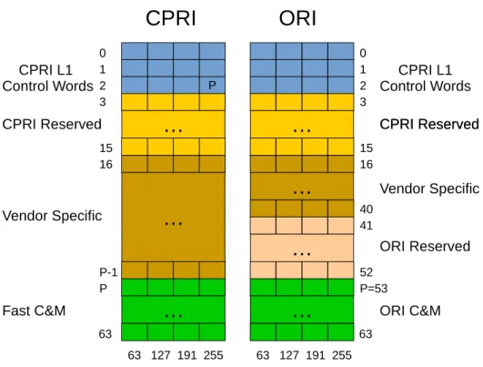
2.8 CPRI and ORI control sub-channels mapping. . . 15
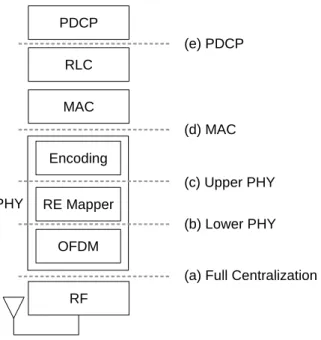
2.9 LTE base station possible functional splits: (a) All process centralized in the BBU, (b) The OFDM modulation is executed in RRU, (c) The resource mapping and modulation is executed in RRU, (d) The whole PHY layer is executed in RRU, (e) All functions except the PDCP is executed in the RRU. . . 19
2.10 PUSQH compression flow graph. . . 23
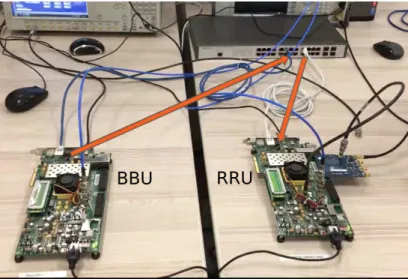
3.1 Hardware setup of the testbed FPGA boards. . . 26
3.2 Fronthaul testbed architecture. . . 26
3.3 Default CPRI Basic Frame configuration. . . 29
3.4 Example of CPRI encapsulation on Ethernet frame. . . 30
3.5 PTP messages and timestamps. . . 32
3.6 Decompressor blocks flow graph. . . 35
3.7 CPRI BF payload for the bit-stream of compressed OFDM symbol. . . 37
3.8 Decompressor with its internal blocks: Huffman and LPC decoders . . . 38
3.9 Huffman decoder internal flow graph. . . 40
3.10 Timing overview of prediction filter input and output signals. . . 42
xiii
3.12 Machines and FIFOs used in CP insertion block. . . 44 3.13 Overview of the cyclic prefix insertion block state machines. . . 45
4.1 Fronthaul testbed blocks. . . 46 4.2 RF LTE signal, after fronthaul transport and decompression. The left graph is
List of Tables
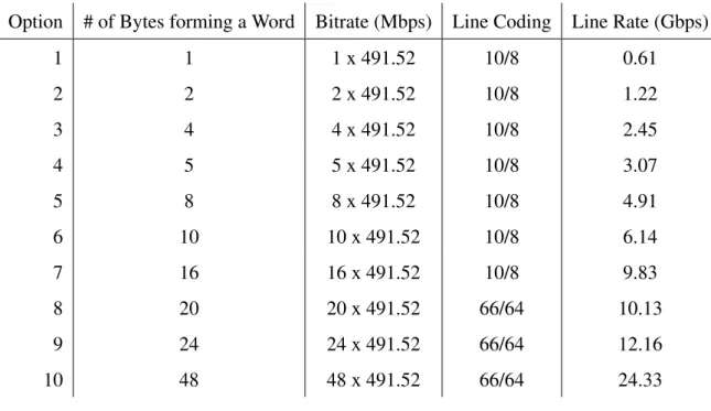
2.1 CPRI configuration for some of the line rates defined in the specification. . . . 9
2.2 Fronthaul requirements of different functional split from [3]. . . 19
3.1 Default parameters of fronthaul’s transported signal used in this work. . . 29
3.2 List of Flags incorporated on the compressed stream. . . 36
3.3 Number of samples and duration per Symbol OFDM in an LTE slot. The length of CP is different for the first OFDM symbol. . . 43
4.1 Hardware Utilization for BBU and RRU. . . 48
4.2 EVM measurements break down of the different LTE channels [4] . . . 49
Contents
Acknowledgment v
List of Figures xii
List of Tables xiv
Contents xv
1 Introduction and Motivation 1
1.1 Objectives . . . 3
1.2 Dissertation Outline . . . 3
2 Fronthaul 5 2.1 Fronthaul Concepts and Existing Technologies . . . 7
2.1.1 Common Public Radio Interface (CPRI) . . . 8
2.1.2 Open Base Station Architecture Initiative (OBSAI) . . . 12
2.1.3 Open Radio Equipment Interface (ORI) . . . 14
2.2 Next Generation Fronthaul Interface (NGFI) . . . 15
2.2.1 Packet-Based Fronthaul . . . 17
2.2.2 Functional Split between BBU and RRU . . . 18
2.3 Fronthaul’s Signal Compression . . . 22
2.3.1 PUSQH Compression Algorithm . . . 22
3 Fronthaul Ethernet Compression Testbed 25 3.1 Ethernet Fronthaul Testbed . . . 26
3.1.1 CPRI Generation and Consuming . . . 27
xvi
3.1.3 Clock Synchronization Procedures . . . 32
3.2 Fronthaul Compression Implementation . . . 34
3.2.1 Unpacking CPRI Basic Frames . . . 36
3.2.2 Decompressor Implementation . . . 38
3.2.3 Huffman Decoder Block . . . 39
3.2.4 Prediction Filter Block . . . 41
3.2.5 Cyclic Prefix Insertion Block . . . 43
4 Testbed Evaluation Results 46 4.1 Testbed evaluation . . . 46
4.1.1 Compression Evaluation . . . 48
4.1.2 The Phase Noise of recovered clock . . . 50
5 Conclusion 53 5.1 Future Works . . . 54
5.2 Publication . . . 55
Abstract
Resumo
Chapter 1
Introduction and Motivation
One of the essential differences between mankind and other animals is the capability to communicate. From the Egypt’s pictograms to the Internet, several techniques have been used to extend the human communication through the time and space. The Electrical Engineering field, in particular, has made several contributions to the communication systems. For example, the telegraph in early 1800’s, the telephone in mid 1800’s and the radio in late 1800’s. But only in the late 1900’s the mobile communication started to take the shape known nowadays, moved by the objective to communicate everywhere with everyone.
The first mobile transceivers were simple full-duplex analog radios, but soon became nec-essary to control the access to radio frequency resources. Then, a more complex network was created with the necessary control mechanism and analog voice transmission, called first gen-eration mobile network (1G). Concurrently, the advances on voice coding and encryption made possible to transport voice over a digital network, which was applied in the second generation mobile network (2G). Also, this generation introduced beneffits such as voice encryption and data services, for example the SMS and MMS.
2
The predictions made by Cisco in [8] forecast an increase in the mobile data traffic by 7x between 2016 and 2021. Additionally, machine-to-machine communications will grow 34% per year in the same period, driven by the Internet of Things (IoT) adoption. Also, the media consumption will increase 9x, accounting as 78% of total mobile traffic in 2021. Furthermore, applications such as real-time video broadcast or tactile internet will require lower levels of network latency and delay. From the operator’s perspective, others requirements are made such as flexibility on deployment, and cost reduction to maintain the Total Ownership Cost (TOC) relatively low.
Such requirements from users and operators shapes the target for the upcomming gener-ation of mobile networks. To address all incoming requirements, the radio access network is evolving to use a variety of technologies. For example, Inter-Cell Interference Coordination (ICIC), massive MIMO (multiple-input, multiple-output), and operation of signals in the mil-limeter wave spectrum. In detail, the ICIC technology provides better signal quality and higher throughput on high interference scenarios. Also, Massive MIMO expands the capacity of the wireless link by the usage of several antennas. Finally, the operation in millimeter waves en-ables the transmission of higher bandwidth signals and provides more spectrum to be allocated. All these improvements being applied to the network require a great deal of engineering effort. Due to the distributed characteristic of the existing mobile network, the implementation of interference coordination and spatial diversity between Base Stations are very expensive. In addition, the operation costs of cell-cites are high, mainly due to energy consumption and rent. In this scenario, the idea of a Centralized Radio Access Network (C-RAN) [9] gained attention, where a set of small and cheap remote distributed nodes are connected to a central processing unit. The cost reduction of this architecture can be around 53% in OPEX and 30% in CAPEX as shown in [10]. Furthermore, a centralized signal processing can make easier to implement the coordination and MIMO techniques expected for next generation mobile network.
Although the C-RAN brings several advantages, there are issues to be addressed in order to benefit from the centralization gains. The fronthaul is very important to the centralized RAN, since it connects the network units that capture and process the radio signals. But, the existing fronthaul technologies are very expensive, given that dedicated optical links are used to provide high bandwidth and low jitter. In this scenario, it is necessary to rethink the fronthaul infrastructure in order to reduce costs while still providing a reliable fronthaul transport.
3
cost networks, such as Ethernet. This strategy should bring the benefits of statistical multiplex-ing provided by a packet-network, along with the re-usage of existmultiplex-ing infrastructure. Also, the hierarchical structure of Ethernet is advantageous for dense deployment scenarios expected for 5G. In addition, the Ethernet protocols also provide a well known and broadly used set of Oper-ation and Maintenance (OAM) functions. In summary, Ethernet is one of the main technologies in the next generation fronthaul.
This work presents a testbed implementation for Ethernet-Based fronthaul, along with the chalenges and solutions to provide reliable fronthaul transport over Ethernet infrastructure. The fronthaul implementation shown here could be used to test and evaluate a variety of algo-rithms for fronthaul and C-RAN. For example, this infrastructure was used to evaluate the LTE signal compression of [11] and the transport of compressed IQ signals. In this evaluation, the compressed data is transported over the fronthaul network, decompressed and sent to the air interface through the usage of an external digital-to-analog converter. In addition the analog signal is fed into a signal analyser in order to evaluate the quality metrics of the signal.
1.1
Objectives
Some of the main objectives of this work are:
• To review the basics of existing fronthaul technologies and future trends.
• To present an implementation of fronthaul architecture based on Ethernet.
• To evaluate the impairments of an Ethernet-Based fronthaul into the transported signal.
• To present an implementation of LTE signal compression algorithm in VHDL.
• To evaluate the quality metrics of signal compression over an Ethernet-Based fronthaul.
1.2
Dissertation Outline
4
in Section 2.2. Finally, an overview of the signal compression technique implemented in this work is shown in Section 2.3.
Chapter 3 presents the implemented Ethernet-based fronthaul testbed with compression. Initially, the used fronthaul architecture is shown in Section 3.1. After, the VHDL implemen-tation of the compression algorithm is detailed in Section 3.2, along with the developed blocks and its engineering solutions.
Chapter 2
Fronthaul
Fronthaul is the name given for the portion of the Radio Access Network (RAN) between digital signal processing and Radio Frequency (RF) signal conditioning. In a high-level view the RAN architecture can be divided in two blocks: The Digital Unit (DU) that modulates the user data into a digital signal according to a specific Radio Access Technology (RAT) and the Radio Unit (RU) which converts the digital signal into analog RF signal. In the existing Base Stations (BS) these two units are connected through a high reliable and fast channel called fronthaul, as show in scenario (b) of Figure 2.1. Over the time the architectural usage of the DU and BU changed as shown in Figure 2.1 and further discussed in this section.
6
The split of DU and RU is a well known practice in the telecommunications world. This paradigm is preserved even when both units are physically located at the same space, as shown in Figure 2.1 (a). In this scenario, the concept of fronthaul already existed, but just around 2002 it started to be standardized as a long range digital link. This transformation was motivated by the necessity to increase the mobile coverage and extended the Base Station through Remote Radio Head (RRH), as shown in Figure 2.1 (b). At that time several telecommunication actors started to define new types of interfaces between both units. The efforts pointed in the same direction, a digital interface using optical-fiber medium with high availability and throughput.
Different protocols were defined for the implementation and deployment of fronthaul links, some of the most important ones are: the Common Public Radio Interface (CPRI) [1], de-veloped by group of companies including: Ericsson, Huawei, NEC, Alcatel, Nokia and others. Also, there were the Open Base Station Architecture Initiative (OBSAI) [2], created by another groups of companies including: Samsung, LG, Nokia, Hyunday and ZTE. Additionally, there is a recent effort based on CPRI to provide more interoperability between different RU’s and DU’s called Open Radio equipment Interface (ORI) [12].
Currently the RAN architecture is going through another round of architectural changes to provide better services at lower costs. These changes are motivated by the high demands for throughput and quality from the consumers, allied with the mobile operators competition for lower costs. In this scenario, the concept of Centralized Radio Access Network (C-RAN) [10] comes up as a solution for cost reduction. As discussed before, this concept proposes to cen-tralize the DU’s functions into computing centers, while keep the RU at the coverage areas, as shown in Figure 2.1 (c). This architecture has many advantages such as cost-reduction on deployment and operation, also it is possible to implement interference coordination algorithms easily with centralized processing.
In order to centralize the resources the fronthaul network needs to be redesigned [13] to support the C-RAN at reasonable costs. The existing fronthaul uses point-to-point optical links, which makes the cost of deployment on dense scenario very high. A fronthaul architecture suitable for C-RAN should benefit from the statistical multiplexing provided by packet net-works. Also, take in account the network traffic on the network scheduling, providing dynamic flow-control based on the network usage.
ex-7
plore the functional split between DU and RU. This means to move some processing from the Base Band Unit to the Remote Radio Head. In this case the RU receives a difference nomen-clature, namely Remote Radio Unit (RRU), due to its additional digital processing.
The existing fronthaul transports raw complex samples and uses huge amounts of band-width. For example, a single 4G-LTE 20 MHz signal can consume up to 1.2 Gbps, assuming the signal is using 40 bits on each complex sample, which is the maximum defined by CPRI in Section 7 of [1]. These bandwidth requirements are unfeasible for the network densification planned in 5G networks, especially in applications that use, e.g., massive MIMO [14], since the fronthaul bandwidth is proportional to the number of antennas used in the RU.
In this chapter a review of the essential characteristics of existing fronthaul technologies is shown in Section 2.1. Then, the research trends of the Next Generation Fronthaul Interface (NGFI) is presented in Section 2.2. Finally, to support the subsequent chapters a brief introduc-tion to the compression algorithm implemented in this work in shown in Secintroduc-tion 2.3.
2.1
Fronthaul Concepts and Existing Technologies
As introduced before, there are three well-defined fronthaul specifications: CPRI, OB-SAI and ORI [15]. Besides having different objectives and procedures, they also have a lot in common when focusing in the fronthaul link itself. For example, both OBSAI and CPRI carry synchronization signals through the fronthaul. Additionally, they all define control and management procedures.
The Common Public Radio Interface (CPRI) specification is an industry cooperation started at 2003 aiming to define a fronthaul link between Radio Equipment (RE) and Radio Equipment Controllers (REC). The CPRI is a essentially simple protocol to transport IQ data, control and synchronization information from the RE to REC. The CPRI is the most widely used fronthaul standard, this specification will be better discussed in Section 2.1.1.
The Open Base Station Architecture Initiative (OBSAI) standard started in 2002 aiming to define a complete architecture for base stations, as will be discussed in Section 2.1.2. The objective of this specification is to standardize the internal blocks of the base station and enable the cell-site to be deployed with equipment from different vendors. The fronthaul as this work defines is actually one of the many interfaces specified by OBSAI standard.
8
by the Industry Specification Group (ISG). This standard is based on CPRI and aims to specify a more detailed Control and Management Procedure. In CPRI most of these operations are vendor-specific, which makes it difficult of using products from different vendors. Furthermore, the ORI specification defines a compression algorithm to be applied on CPRI signals with large bandwidth [12]. The ORI will be briefly discussed in Section 2.1.3
2.1.1
Common Public Radio Interface (CPRI)
The CPRI specification is the commonly used standard of fronthaul. It defines a commu-nication link between the DU and RU, in fact these entities are called respectively Radio Equip-ment Controller (REC) and Radio EquipEquip-ment (RE) in CPRI specification. The link carries not only the complex signal (IQ Data), but also control and clock synchronization information, as shown in Figure 2.2. The CPRI payload can carry several IQ signals, each one encapsulated into an Antenna Carrier (AxC). It can transport different communication protocols, such as GSM, CDMA, LTE or WiMAX. Also, the protocol counts with a set of control information such as Control and Management (C&M) data, protocol extensions and vendor specific information [1].
Figure 2.2:Information carried in CPRI link.
synchroniza-9
tion. After all the synchronization procedures the CPRI link is capable of achieving a maximum frequency error of 0.002 ppm, and delay accuracy of 16.276 ns [1].
The CPRI specification defines both Optical and Electrical media but it does not describe how the physical layer should be implemented. In fact, the standard just specifies the perfor-mance requirements of the PHY such as the Bit Error Rate (BER) under10−12 and the link line-rates, which are listed in Table 2.1. Although the specification defines an electrical inter-face the existing CPRI deployments for long distances are made with optical medium. The Electrical interface is commonly used in backplane implementations or short distances cooper cabling, under 10 m [1].
Table 2.1: CPRI configuration for some of the line rates defined in the specification.
Option # of Bytes forming a Word Bitrate (Mbps) Line Coding Line Rate (Gbps)
1 1 1 x 491.52 10/8 0.61
2 2 2 x 491.52 10/8 1.22
3 4 4 x 491.52 10/8 2.45
4 5 5 x 491.52 10/8 3.07
5 8 8 x 491.52 10/8 4.91
6 10 10 x 491.52 10/8 6.14
7 16 16 x 491.52 10/8 9.83
8 20 20 x 491.52 66/64 10.13
9 24 24 x 491.52 66/64 12.16
10 48 48 x 491.52 66/64 24.33
The smallest portion of a CPRI stream is the Basic Frame (BF), it has a unique character-istic, independent of the line rate used the BF has to depart at the fixed rate of 3.84 MHz, this rate is called chip-rate and is a legacy from CDMA applications. In other words, independent of the CPRI line rate, at each 260.41 ns there is a BF departing. The BF is divided internally into 16 words, as shown in Figure 2.3, the bit-width of these words changes with the line-rate option. For example, in the line-rate option 1 the bit-width of each word is 8 bits, while in the line-rate option 2 each word carries 16 bits. Also, the first word of each BF is reserved for CPRI control information, namely the Control Word (CW).
10
Figure 2.3: CPRI Basic Frame internal structure [1].
form a block of samples from the same antenna as ilustrated in Figure 2.4. The BF can carry several AxC’s, organized in ascending order, as long as the link capacity is respected. The number of samples in each AxC container depends on the oversampling ratio with respect to the chip-rate (3.84 MHz). Inside each AxC, the samples are stored in chronological order and consecutively, from LSB to MSB, with interleaved I and Q samples, as shown in the Figure 2.4. Both Figures 2.3 and 2.4 shows the same CPRI BF setup. They both have a control word of 8 bits followed by a data block of 120 bits, divided in 15 words of 8 bits. Note that the IQ samples of Figure 2.3 does not necessarily use an integer number of words from the data block. In fact, the data block is divided for each antenna carrier and the samples are allocated inside the AxC accordingly to the transported signal.
Figure 2.4:Example of CPRI Basic Frame carrying two signals with 30 bits per IQ sample.
11
Frames, W indicates one of 16 words within the Basic Frame, Y indicates the byte within a word and B indicates the bit in each byte, as shown in Figure 2.5.
Figure 2.5:CPRI naming convention and frame structure [1].
The control words are grouped by hyperframes, each one has 256 Control Words which carries different types of control information. For example, a hyperframe Synchronization word is carried in the first word of each hyperframe. Also, some words are used to allow the com-munication between the PHY layers of endpoints, called L1 Inband Protocol. In addition, there are words carrying special sequences to help the PHY layer to train is internal PLL’s in order to acquire the synchronization. Aside from these fields, there is also space for vendor specific information and others.
The amount of bits to be carried in each BF is dependent on the number of AxC containers (NAxC), the amount of bits per IQ-sample (IQb) and the sample rate (Fs) of each AxC signal.
As a matter of fact, the CPRI bit-rate (RCPRI) has to be chosen based in the equation:
NXAxC
i=0
IQb,i×Fs,i≤
15
16×RCPRI, (2.1)
where the15/16value represents the Control Word overhead. For example, a CPRI stream with two AxC (NAxC = 2), carrying an LTE 20 MHz signal (Fs = 30.72×10⁶), with IQ samples
represented by 30 bits (IQb = 30), consumes a bit-rate around 1.84 Gbps. Although the closest
12
Although CPRI is the commonly used protocol, it has a very small protocol defition. On one hand such simplicity makes the standard very flexible and can be applied in different scenarios, on the other it became difficult to assure the interoperability of equipment based only in CPRI specification.
2.1.2
Open Base Station Architecture Initiative (OBSAI)
As discussed before, the OBSAI standard defines a whole architecture for the Base Sta-tion, including a fronthaul link [2]. The specification defines several basic blocks and interfaces, as shown in Figure 2.6. For example, theBase Band Blockmodulates the information into the IQ signal, while theRF Block converts the IQ signal to analog RF. Moreover, theControl and Clock Blockgenerates clock synchronization and control information to all the blocks.
Figure 2.6:Overview of OBSAI building blocks [2].
The protocol [17] also specifies the interfaces between the blocks: the Reference Point 1 (RP1) distributes synchronization and control information between the blocks. In addition, the Reference Point 2 (RP2) interfaces theBase Band BlockwithTransport Blocktransporting the user data. Also, there is the Reference Point 3 (RP3) transports the samples betweenBase Band
andRF Blocks.
13
are provided by three different entities. To extend the range of a divided architecture like this it is necessary a converter to group these information into a single channel. In this scenario, the OBSAI standard defines an extension to the RP3, called RP3-01, to make possible the utilization of Remote Radio Units. On RP3-01 the IQ-Data, Control and Synchronization are carried together into a single long-range link. In this extension the network topology is restricted to chain, ring or tree, just like CPRI. Although the optical link is more commonly used, the RP3-01 also specifies other media such as wireless and cooper cable, as long as the transmission characteristics can met the standard [2].
There are many similarities between OBSAI RP3-01 and CPRI, as shown in Figure 2.7. For example, both are capable to transport the same Radio Access Technologies: GSM/EDGE, CDMA, WCDMA, WIMAX and LTE. Also, both use a reference signal derived from physical layer to provide system-wide clock synchronization. In addition, both standards define optical and electrical interfaces. The former is applied in long-range applications while the latter is used in backplane applications.
Figure 2.7:Information carried by OBSAI RP3 link.
14
The OBSAI is a very extensive standard, since it describes the complete architecture of a BS. For example, the C&M procedures for RP3-01 are more complex than the CPRI ones. This reduces the implementation freedom in the fronthaul, but allows the compatibility be-tween equipment. The detailed study of OBSAI specification is out of scope of this work, but it is essential to evaluate the similarities and differences among the available fronthaul techonolo-gies.
2.1.3
Open Radio Equipment Interface (ORI)
The ORI protocol [12] is fully compliant with CPRI specification. In fact it can be seen as an extension to the CPRI specification to provide more interoperability between equipment from different vendors. Among the extensions defined by ORI, the compression of IQ data is an important topic. The standard specifies how the compression should be made and also the allowable degradation such as EVM and latency. Also, in the control and management domain the specification defines software abstractions and configurations not covered by CPRI.
Besides it is possible to compress the stream transported by CPRI, which does not spec-ifies how the signal can be compressed. The ORI, on the other hand, defines a compression technique to be used for the LTE signals with BW higher than 10 MHz. The specified algorithm uses a 3/4 down-sampling and non-linear quantization to remove the redundancy in both fre-quency and amplitude domains. The protocol also defines how the compressed stream should be mapped in the IQ-data space. Despite the fact that down-sampling provides a 3/4 compres-sion ratio, the final comprescompres-sion ratio is not defined in the specification, since it depends on the statistical characteristics of the signal and the number of bits used in the non-linear quantiza-tion [12].
The control and managements features of ORI are much more complete than CPRI. The REC counts with a resource model to store the information of the Radio Equipment (RE). In fact, the REC interfaces with the resource model creating an abstraction layer between the nodes. The resource model provides functionalities to manage the Configuration (CM), State (SM) and Faul (FM) of each RE. With this software abstraction, it is possible to make changes in the RE without directly changing the REC.
vendor-15
specific and Fast C&M sub-channels are remapped to allocate ORI data. The vendor-specific area is reduced and gives place to an ORI reserved area, as shown in Figure 2.8. Also, the CPRI’s Ethernet data-link protocol defined in Fast C&M became a full TCP/IP stack protocol in ORI C&M. The usage of a full stack makes possible to use other well-known protocols in the ORI link. For example, it is possible to use DHCP for IP address distribution and FTP for configuration file transfer.
Figure 2.8:CPRI and ORI control sub-channels mapping.
As seen in Figure 2.8, the vendor specific fields are not removed from ORI, but they use a reduced space. In CPRI the vendor specific area had a configurable amount of words from 15 to 192. However, in ORI these fields uses 100 words while the rest of the Control Words are divided between ORI Reserved fields and ORI C&M link, the former uses 48 words while the latter uses 44 words.
2.2
Next Generation Fronthaul Interface (NGFI)
16
objective of the fronthaul in the next generation is to enable the radio access network centraliza-tion and reduce the costs of network deployment. Of course, the centralizacentraliza-tion itself can bring several benefits such as resource re-utilization, virtualization and better spectrum usage.
The traffic demand shaped the evolution of physical layer modulation and coding tech-niques. As a result, the single-link capacity is very close to the Shannon’s limit. On the other hand, the usage of multi-antenna techniques multiplied the overall link capacity, which gener-ates the necessity of Base Stations with even more antennas. In addition, the signal interference once seen as a problem to be fought, now can be used constructively to increase the signal strength. In this scenario, the fronthaul has to connect several coordinated Radio Units to the central BS processing.
As shown previously, the existing fronthaul distributes the IQ samples, control and syn-chronization information, thus the NGFIs should be capable to transport the same information with lower costs. Between the difficulties to produce such network is the prohibitive amount of bandwidth used in the existing fronthaul. As already discussed, an LTE signal can consume it to 1.2 Gbps from the fronthaul. Obviously such bit-rate values can be decreased by reducing the number of bits used to represent each sample, but this will deteriorate the signal quality.
Moreover, the usage of dedicated optical links to transport the fronthaul information in-creases the overall cost of the network. Although the Wavelength-Division Multiplex (WDM) technology can be applied to aggregate several optical channels into a single optical fiber, the equipment cost is still high. On the other hand, the widely used Ethernet equipment provides a low-cost industry standard solution. In addition, the usage of packet-based statistical multi-plexing promises gains to the network efficiency. Also, Ethernet is very simple to deploy and scale, which makes the Ethernet transport a desired solution for NGFI. In addition the Ethernet protocols already have a complete set of OAM functions for troubleshooting and management
17
2.2.1
Packet-Based Fronthaul
As discussed before, the existing fronthaul uses dedicated optical links due to the strict requirements of the fronthaul specification. However, this deployment is inefficient from the perspective of network utilization. For example, at night when the network usage decreases, the fronthaul link has to be active to provide the coverage, even if there is no user to be covered. Due to its static configuration, the existing fronthaul can not benefit from the tidal wave effect of network usage, which is the cyclic variation of the network load over the day.
On the other hand, packet-based networks such as Ethernet are very efficient to accommo-date on network usage changes, due to the packet switching methodology. As said before [18], both industry and operators agree that the NGFI should be packet-based. In fact, this paradigm change would bring more flexibility to the fronthaul, although it is necesary to evaluate the challenges generated by the packet network.
There are two ways to think the adaptation of the fronthaul to packet-based network. The first consists to evolve the Ethernet infrastructure to provide the fronthaul requirements. An-other is to change the base station architecture to take in account the packet-based impairments. There are several groups discussing which techniques should be used and the optimal solution, such as the IEEE-1914 [19] and IEEE-1904.3 [20].
Of course, the existing Ethernet infrastructure is not reliable: the best-effort characteristic forces the higher layer protocols to have extra procedures to assure the information transport. On the other hand, there is work being done in the IEEE Time-Senstive Network (TSN) task force to assure the quality of service for streams being transported over the Ethernet. The aforementioned task force specifies some techniques to assure the Ethernet quality such as: Scheduled Traffic [21], Frame Preemption [22] and Link Reservation [23].
The Ethernet standard is evolving to provide transport with less Packet Delay Variation (PDV) and Round Trip Time (RTT) while maintaining the high throughput. On the other hand, fronthaul requirements are very tight. A transport network to provide such parameters will eventually not be cost effective. In this scenario, the fronthaul has to introduce techniques to overcome the Ethernet impairments, and provide the fronthaul transport even on imperfect Ethernet network.
18
RTT requirements for fronthaul can be relaxed by rethinking the time budget over the commu-nication stack. Since on centralized architecture the upper layers of the stack will use less time to communicate inside a Radio Computing Center.
In addition, the signal compression techniques shall evolve to provide more signal quality in bandwidth limited scenarios. Also, the evolution of transport protocols of fronthaul over Ethernet should provide more robustness to the network impairments, such as packet drop and network congestion. In this scenario, a desirable feature is the adaptation of the compression ratio to the network load state.
Although the centralization shall facilitate the implementation of MIMO and interfer-ence mitigation/coordination techniques, these applications require frequency, phase and time synchronization between the network nodes. In such circumstances, it is possible to use the Precision Time Protocol (PTP) [24] to provide the required synchronization. The PTP is a network protocol defined by IEEE-1588 and used in packet-based networks to provide clock synchronization.
Aside from PTP it is possible to use different synchronization sources over Ethernet fron-thaul. For example, the Global Navigation Satellite Systems (GNSS) which is an effective solution to synchronize outdoor nodes. Moreover, it is possible to distribute synchronization through the physical layer as implemented in the ITU G.8262 specification, called SyncE [25]. This solution requires an special implementation of the Ethernet physical layer, since the Eth-ernet is intrinsically asynchronous.
The discussed impairments and solutions does not require the Radio Access Technology to be upgraded. On the other hand, by adaptations to the RAT it is possible to achieve better results in the centralization over a packet-based fronthaul. This scenario will be discussed in the next Section.
2.2.2
Functional Split between BBU and RRU
19
There are different scenarios for functional split, for example the scenario implemented by CPRI and OBSAI is the full-centralization, shown in Figure 2.9 as (a). In this scenario, the RRU just contains the analog converters and RF conditioning circuitry, in other words all the signal processing and upper layers are executed in the BBU. As a result, this scenario demands high throughtput and low latency from the fronthaul. For example, in CPRI the maximum RTT is 5µs, while the bandwidth for an LTE signal 20 MHz with 2x2 MIMO can be up to 1.8 Gbps, as shown in Table 2.2.
Figure 2.9: LTE base station possible functional splits: (a) All process centralized in the BBU, (b) The
OFDM modulation is executed in RRU, (c) The resource mapping and modulation is executed in RRU,
(d) The whole PHY layer is executed in RRU, (e) All functions except the PDCP is executed in the RRU.
Table 2.2:Fronthaul requirements of different functional split from [3].
Scenario BW* RTT Latency
(a) 1.8 Gbps 5µs 150µs
(b) 590 Mbps 1 ms 150µs
(c) 86 - 530 Mbps1 3 ms 150µs
(d) 70 Mbps1 3 ms 2 ms
(e) 70 Mbps1 100 ms 5 ms * Based on an LTE 20 MHz 2x2 MIMO signal
20
The full-centralization scenario can provide complete centralization gains. On the other hand, the fronthaul necessary to accomplish this objective has very high requirements, which increase the overall cost of the fronthaul network. Not only the necessary bandwidth is very high but also the RTT delay and latency are very low, which requires a big effort to encapsulate this type of network on the existing Ethernet infrastructure.
Other functional splits are also possible, for example to offload the OFDM processing into the RRU, as represented in scenario (b) of Figure 2.9. In this scenario, just the frequency domain IQ samples are transported over the fronthaul, while the OFDM processing including the Cyclic Prefix insertion are executed in the RRU. This type of split can reduce the fronthaul bandwidth up to 30%, as shown in [3]. Also, the RTT delays are relaxed due to the LTE framing structure. On the other hand it is still attached to the LTE slot boundaries.
The Lower PHY scenario reduces the bandwidth requirements from the fronthaul, and is still capable to centralize the MIMO precoding operations. In addition, the interference coor-dination technique can also be applied in the frequency domain before the OFDM modulation. On the other hand, this scenario still demands very tight latency requirements, which makes difficult the usage of several hops in a Ethernet network.
Another important split is the scenario (c) in Figure 2.9, called Upper PHY. In this sce-nario, the resource mapping and all the modulation is made in the RRU. This method actually benefits from the eventual low usage of the LTE signal, since the unused Resource Blocks (RB) will not be transported over the fronthaul. In this scenario, the network tidal wave effect could be used to reduce the required bandwidth on low network usage.
Although the Upper PHY method provides lower bandwidth requirements, the centraliza-tion gains is also lower. Since in this method the MIMO precoding is moved to the RRU, it is more difficult to implement spatial multiplexing techniques. In addition, the latency require-ments are still very tight due to the channel information validity. In fact, all the PHY based split functionalities suffer from the same effect, since the maximum allowed latency has to be within the channel information valid period.
21
Although for the fronthaul such relaxed parameters would represent a cost reduction, the gains with centralization would be low, given that most of the processing would be made in the RRU. But, In this scenario, it still possible to achieve some gain by the application of Coordinated Scheduling [27, 28]. In such method, the transmission of each node in the network is scheduled in order to reduce the overall interference.
The last functional split reviewed here, is the scenario (e) of Figure 2.9, which is actually very similar to the distributed architecture currently available. Such method centralizes the higher layers of the base station such as RRC and PDCP. In this scenario, the bandwidth usage on the fronthaul is slightly lower than the previously shown scenario (d). On the other hand, the RTT and latency are relaxed since there is no boundaries from the HARQ operations.
The low requirements of scenario (e) makes this functional split desirable, even if the centralization gains from coordination and interference mitigation are nonexistent. In fact, this scenario is already provided by products such as the Ericsson solution for C-RAN [29].
As discussed, each functional split can provide different requirements for the fronthaul and respectively distinct centralization gain. The possibility to relax the requirements on Ethernet-based fronthaul is very interesting to be applied on the scenarios where the Ethernet network is congested. With the different functional splits, a centralized controller can be able to chose the optimal scenario depending on the network state.
2.2.2.1 Antenna Independent Traffic
To satisfy the predicted increase in the network usage, hundreds of antennas are planned to be used on the Radio Access Technology. In this scenario, it is very desirable to transport a single stream independent of the number of antennas and separate this stream in the RRU. This is actually a trade-off with the centralized processing expected for interference coordination and mitigation. From one side it is useful to centralize the process, but with massive amount of antennas, the fronthaul will have problems to transport these signals.
22
2.2.2.2 BBU and RRU dynamic mapping
Another important topic is the mapping between BBU and RRU, that means which BBU will process the signals of each RRU. In the existing network this mapping is static and realized at the network configuration, but the fronthaul can enable a more flexible mapping. For exam-ple, on high traffic demands the network can choose to share the processing between different BBU pools. In this scenario, the fronthaul has to follow a defined mapping between RRUs and BBUs.
In addition, there is a cost reduction attached to a flexible mapping, since in the low usage scenarios the network could centralize the processing and turn-off the unused resources. In fact, this dynamic topology changes can benefit even more from the tidal wave effect in the network usage.
2.3
Fronthaul’s Signal Compression
The bit-rate is a critical resource for the NGFI mainly due to the high requirements defined in the existing fronthaul network. As seen in the previous sections, it is possible to reduce these requirements by the usage of different functional split between BBU and RRU. On the other hand, this technique also changes the achieved centralization gains. Another possibility to reduce the bandwidth requirements while still providing the centralization gain is to compress the signal transported over fronthaul.
This section discusses the algorithm used as basis for the compression implementation made in this work.
2.3.1
PUSQH Compression Algorithm
The compression implementation made in this work uses the algorithm Predictive Uni-form Scalar Quantization with Huffman (PUSQH), described in [11] and developed at UFPA. This algorithm compresses the LTE signals to be transported over the fronthaul. It is a combina-tion of OFDM adapted Linear Predictive Coding (LPC) and Huffman coding. This seccombina-tion will give a high-level view of the algorithm while the deep theoretical investigation can be found in [11].
23
step is to remove the cyclic prefix of the OFDM signal creating the signalx[n], where0≤n < N−1andN is the number of samples per OFDM symbol. The firstP samples of each OFDM symbol are used to initialize the predictor filter in both, the encoder and decoder, as proposed in [11]. The remaining samples ofx[n]are encoded with LPC and Huffman.
In PUSQH the compression is applied on each time-domain OFDM symbol. The first step to be made in order to compress the signal is to remove the Cyclic Prefix, as show in Figure 2.10. Then, a Linear Predictive Coding (LPC) is applied to the signal and derives an error reference that represents the difference between the original signal and the predicted one. Finally, the error signal is compressed with Huffman code in order to further reduce the amount of bits transported.
Figure 2.10:PUSQH compression flow graph.
The difference between the original signal and predicted signal, called prediction error, has a lower variance than the original signal. Thus, LPC enables to compress the prediction error with lower bits than the original signal and achieve the same level of distortion.
Based in the linear prediction theory [30] it is possible to estimate a system that predicts the behavior of a given signal, based on its characteristics. For example, the Levinson-Durbin algorithm uses the auto-correlation information of a signal to derive a FIR filter that can predict the next samples under certain error, based on a linear combination of the previous samples.
As a matter of fact, the PUSQH usage of prediction and quantization is also known as Differential Pulse-Coded Modulation (DPCM). It is a compression algorithm based in closed-loop predictive quantization. Such strategy is commonly used in the compression of audio and video and was shown by [11] that it can be also customized for LTE signals.
The P initial samples of each OFDM symbol are used to initialize the predictor filter, so these samples are losslessy encoded and transmitted to the decoder. This operation resets the prediction filter at the beginning of each OFDM symbol and is very important to keep the error within an acceptable range, as shown in [11]. Also, this imposition will drive some key project decisions in the hardware implementation.
24
Huffman coding to the quantized error, in order to reduce the necessary amount of bits to be transported, without further distortion. This technique also benefits from the statistical charac-teristics of the error signal, since the probability distribution of the quantized error is approxi-mately Gaussian.
Chapter 3
Fronthaul Ethernet Compression Testbed
As discussed in the previous sections, the usage of common Ethernet links to carry fron-thaul streams could bring more flexibility and lower cost to the Next Generation Fronfron-thaul Interface. In this context, the compression of fronthaul traffic is an enabling technology that reduces the huge requirements of the fronthaul transmission rate.
Similarly to the existing fronthaul technologies shown in Section 2.1, the hardware setup presented here consists of a BBU and RRU. The BBU reads LTE signals from its memory and sends over the network through the implemented fronthaul infrastructure. On the other end, the RRU receives Ethernet frames containing fronthaul data and recovers the transported LTE signal. At last the LTE signal reconstructed in the RRU is sent to an analog front-end to be analyzed in the real-world by external equipment.
The presented fronthaul testbed is implemented mainly in VHDL. Other resources were used such as IP-Cores and C code. In detail, the IP-Cores have been used for common hardware blocks such as the interfaces with Ethernet, Memory, and ADC/DAC interfaces. Also, the C language was used in software drivers to initialize and control the testbed. Moreover, MATLAB plays an important role to generate and validate the parameters used to configure the VHDL implementation.
26
Figure 3.1:Hardware setup of the testbed FPGA boards.
This work presents an architecture to test and evaluate strategies and algorithms for next generation fronthaul that uses Ethernet as infrastructure, as detailed in Section 3.1. Further-more, the work uses the architecture to implement a compression algorithm for LTE signals, as described in Section 3.2.
3.1
Ethernet Fronthaul Testbed
The fronthaul architecture presented in this work aims to map a CPRI stream into Ethernet frames. In other words, the CPRI data is generated and mapped into Ethernet frames. As shown in Figure 3.2, the proposed architecture employs two pairs of blocks: one to generate and consume CPRI streams and other to convert them into Ethernet Frames. Additionally to the CPRI traffic, there is also clock synchronization packets traveling over the Ethernet link provided by the IEEE-1588 protocol.
27
The blocks are designed to be reused on both Downstream (from BBU to RRU) and Upstream (from RRU to BBU) since the operation executed by each block is the same on both scenarios. On the other hand, the block configured for BBU operation have different input and output than in RRU. For example, theCPRI Source block at BBU receives samples from memory while the same block in RRU receives samples from the analog front-end.
The synchronization procedures defined on IEEE-1588 protocol, and further discussed in Section 3.1.3, use a special implementation strategy. In fact, these operations are hardware-assisted, which means that most of the protocol is implemented in software except the proce-dures that need strict timing. For example, the protocol messages are generated in software but fields with departure and arrival times are populated in hardware.
Figure 3.2 is a simplified block diagram of the implemented hardware. In fact, there are some extra blocks used to interface with external medium which are commonly available as IP-Blocks. For example, there are blocks specialized to read/write to FPGA’s on-board memory. Also, there are others to send/receive data frames over Ethernet protocol on MAC and PHY layer. Equally, there is a block to interface with an analog front-end in order to reconstruct the signal in the real-world. Finally, the setup also counts with an embedded processor to run the necessary software drivers.
In addition, the majority of blocks have inputs and outputs compliant with the AXI-Stream protocol. This standard is part of the Advanced Micro-controller Bus Architecture (AMBA) an open-standard developed by ARM. The AXI-Stream is a specification for high-speed data streaming without support for address resolution, but with support for traffic flow-control. In fact, the AXI-Stream is normally used in point-to-point scenarios making not necessary the address resolution. This large utilization of AXI interfaces makes possible to reuse the blocks of the architecture in other scenarios. More information about AXI interfaces can be found in [31, 32]
The following sections will discuss more about the architecture, configuration and imple-mentation details of each block.
3.1.1
CPRI Generation and Consuming
28
the CPRI Frame structure and CPRI departure timing have been implemented according to the standard specification. The objective is to implement the minimal subset of CPRI specification that still makes possible to evaluate the effects of Ethernet over CPRI.
The delineated blocks are calledCPRI SourceandCPRI Sink. Both are statically con-figured to reproduce a specific CPRI framing structure. The CPRI line rate (NR) is one of these
static configurations and indicates the throughput of CPRI stream. Another configuration is the number of Antenna Carrier Containers (SAxC) used to indicate how many LTE signals each BF
carries. Finally, the number of bits per IQ-Sample (IQb) which defines how much data per
sample is inserted in each BF.
As discussed in Section 2.1.1, the aforementioned parameters are bounded by the Equa-tion 2.1. To reduce the degrees of freedom over this equaEqua-tion, some assumpEqua-tions have been made. Initially, it is assumed the whole BF payload is used so the inequality became an equal-ity. Then, the CPRI line rate option 1 that has a bit-rate 491.52 Mbps is chosen to prevent the full usage of Ethernet link that has a peak rate of 1 Gbps, taking in account the encapsulation of CPRI into Ethernet will also add some overhead. As a result, (2.1) is reduced to the following equation:
NXAxC
i=0
IQb,i×Fs,i =
15
16×491.52 = 460.8M bps, (3.1)
which depends only on the LTE signal configurations.
Any configuration that satisfies (3.1) can be used. Since the employed analog front-end provides two LTE signals at the same time, theNAxCwas set to 2. Also, the objective was to use
the full dynamic range of the analog front-end. In order to accomplish that both sample rate and number of bits per sample have been chosen as 7.68 MHz and 30 bits. This sample frequency is relative to an LTE signal with bandwidth of 5 MHz [4]. All the presented values are recurrent over the work and composes the default configuration, as summarized in Table 3.1.
29
Table 3.1:Default parameters of fronthaul’s transported signal used in this work.
Symbol Value Description
FS 7.68 MHz Sample rate of transported LTE signal
IQb 30 bits Number of bits on each LTE sample
NAxC 2 Number of AxC transported by CPRI
NR 1 CPRI Line Rate Option (see Table 2.1)
Nsamples 2 Number of complex samples per AxC container
Figure 3.3:Default CPRI Basic Frame configuration.
block has one AXI-Stream input to receive CPRI data and two output buses, one forDMAand other forDACoperation.
The CPRI Source has to generate the BF exactly at the chip-rate (3.84 MHz). Since this block works at a base clock of 100 MHz, it is necessary some flow-control mechanism to provide the expected output BF rate. To accomplish that, the block uses an additional external clock derived from the reference used in IEEE-1588 protocol. This clock is multiple of the chip-rate and drives the input rate of samples in the CPRI Source. Since the sample rate changes with the type of LTE signal used, it is necessary to reconfigure the clocks for each signal. For example, in LTE 5 MHz the sample rate is 7.68 MHz, which is 2 times bigger than the chip-rate, so the additional clock should also use the same frequency.
3.1.2
Encapsulation of CPRI into Ethernet
30
CPRI BF.
Since the IEEE 1904.3 specification [20] is a work in progress, this work implements its own version of the Structure Agnostic Mode. The blocksCPRI to EthernetandEthernet to CPRIimplements this operation of conversion between CPRI stream and Ethernet frames. The essential procedure is to accumulate a configurable amount of CPRI BFs and generate a single Ethernet frame. Additionally, a custom header is created with meta-data information from the frame such as: the number of encapsulated BF, the sequence number and a departure/arrival timestamp. This structure is depicted in Figure 3.4.
Additionally to the Ethernet header, there is an extension header called fronthaul Meta-Data. This extension provides useful information between the encapsulator and decapsulator blocks. For example the timestamp field is used to log the departure and arrival times of each Ethernet frame. Also, the sequence number field is necessary to discover possible frame drops and error conditions. Finally, the number of BF in the Ethernet Frame is used to indicate how much data must be recovered.
Figure 3.4:Example of CPRI encapsulation on Ethernet frame.
The Generated Ethernet frame contains three protocol layers: the Ethernet MAC, the fronthaul meta-data and the CPRI stream, as shown in Figure 3.4. The addition of these headers increases the overhead (OV) of the CPRI Stream. Of course, the overhead reduces with larger values ofNBF, as calculated in the following equation:
OV = Hs
(NBF ×128)
, (3.2)
where theHs value is the total amount of bits used for headers. For example, the total number
31
11% in a frame withNBF = 16.
Also, there is a latency created by BF accumulation before the Ethernet frame encapsula-tion, which generates a delay variation on the BF delivery. The BFs are generated by CPRI at the exact rate of 3.84 MHz. The encapsulation process adds some latency since the first BF will wait until theNBF-th BF to departure. It is possible to calculate the maximum jitter by
eval-uating the time that the first BF has to wait, which can be calculated as show in the following equation:
J =NBF ×260ns, (3.3)
by multiplying the number of BF (NBF) by the period of each BF (260 ns).
Header overhead and jitter are intrinsic to the encapsulation process based on the Structure Agnostic Mode. These impairments are mainly dependent on the number of BF each Ethernet frame transports. When the number of BF per packet increases, the jitter also increases and the proportional overhead reduces, and vice-versa. In this work the default value ofNBF is 16,
which leads to an overhead of 11% and a peak jitter of 4.1µs.
Despite these impairments affecting the CPRI stream encapsulated over Structure Ag-nostic mode, there are techniques to deflect these effects. The overhead impairment is easily removed by the usage of more bandwidth as long as the Ethernet link is not fully used. Other-wise, the jitter can be extinguished by implementing Dejjitering Buffers, which stores the BF before forwarding. This technique is a form to reduce the jitter by increasing the average delay. Some configurations of the blocks can be changed in real-time, using a software driver. For example, the number of BF into each Ethernet Frame, as already discussed. Likewise there are other configurations such as the Ethernet frame header fields: MAC source/destination addresses and Ethernet Frame Type. It is also possible to enable/disable the block operations by software.
32
3.1.3
Clock Synchronization Procedures
The IEEE-1588, also known as Precision Time Protocol (PTP, see e.g. [33]), is a standard describing procedures to ensure the signal synchronization over a packet network. synchroniza-tion can be divided into three components: the syntonizasynchroniza-tion, phase synchronizasynchroniza-tion and time synchronization. Syntonization is related to the signal’s frequency and aims to make the clock rate the same at both ends of the network. Phase synchronization otherwise aims to make both signals have the rising edge at the same instant. Finally, time synchronization is related to the time of day representation on network nodes.
The PTP uses a set of timestamped messages to discover the delays of the network. A visual representation of the PTP messages over the time is shown in Figure 3.5. In this repre-sentation, there is a master node, which has a high fidelity clock also know as Stratum 1, and a slave node which intends to synchronize to the master’s clock over the network. The handshake shown intends to collect the timestamps T1, T2, T3 and T4 in the slave node, so it can measure and correct the offsets of its local oscillator to the master oscillator.
Figure 3.5:PTP messages and timestamps.
The handshake starts by the SYNC message, which is timestamped on both departure (T1) and arrival (T2). Since T1 value just exists on the master another message, called FOLLOW UP, is sent carrying this information. Then, the slave executes the same procedure sending the DELAY REQ message to the master. This message is also timestamped on departure (T3) and arrival (T4). Finally, the slave receives from master the DELAY RESPONSE message containing the T4 value.
33
procedure is implemented closer to the Ethernet PHY. As long as the timestamping is accurate, the message departure instant does not need to be so strict. Then, the PTP implementation is normally done as a hardware-assisted protocol. The messages are created and send by a software implementation while the timestamping is executed in real-time by the hardware.
The syntonization or frequency synchronization can be achieved based on sequential val-ues of T1 and T2 measurements. In other words, it is based on a one-way communication since the messages from slave to master are not used. Assuming two measurement realizations (T1,k,
T2,k andT1,k+1,T2,k+1), it is possible to calculate the frequency offset (y) by the equation:
y= (T2,k−T1,k)−(T2,k+1−T1,k+1)
T1,k−T1,k+1
. (3.4)
This result assumes there is no influence of the network on the measurements, but if the network is congested there is also a noise parcel in the result.
To find the phase synchronization, all the timestamps of the handshake are necessary. The phase error (x) can be easily calculated when the one-way delay of the path (d) is known, asˆ shown in the following equation:
x=T2−(T1+ ˆd). (3.5)
Also, the one-way delay can be calculated by:
ˆ
d= Tms−Tsm
2 =
(T4−T1)−(T3−T2)
2 . (3.6)
Specially, the delay calculation assumes there is no network delay asymmetry in the path. If the delay is asymmetrical, a parcel of noise will be added to the delay calculation and also the phase offset. Finally, the time synchronization is also achieved through message handshake, but in this case it is not necessary strict timestamping since the objective is to correct the time representation of the slave.
34
Since the network can introduce a big amount of noise into the PTP offset calculations, the protocol defines switching functionalities, which are capable to measure and signalize how much time each packet spent inside the switch, called residence time. With these correction values from the network, it is possible to have precise values for each timestamps (Tn) leading to better offset estimations. Current switches with these PTP functionalities are expensive and increases the cost of the network. On the other hand, the usage of Ethernet infrastructure with PTP support is still cheaper than other solutions such as GPS or dedicated synchronization links.
3.2
Fronthaul Compression Implementation
The architecture described on the previous section can be used to evaluate the implemen-tation of several algorithms for fronthaul over Ethernet. With this testbed, the compression algorithm described in Section 2.3.1 was implemented and evaluated. In fact, from the archi-tectural perspective shown in Figure 3.2, the compression algorithm can be placed inside the CPRI Source and Sink blocks. To put it differently, the compression is executed before the CPRI encapsulation and the decompression is performed after CPRI unpacking. This work in particular implements the Decompressor block on the RRU while the compression operation is emulated by forwarding compressed samples from BBU’s memory.
The CPRI Sink block already receives and decodes the BF. The Decompressor then re-ceives the BF payloads and decodes its contents. There is one Decompressor instance for each AxC. Since the default configuration uses two AxC there are two Decompressor instances. Each instance is formed by the pipeline shown in Figure 3.6. TheFrame Unpackrecovers the compressed stream of each signal component (I and Q). Both streams are passed through the decompression algorithm implementation onDecompressor block. Finally, the cyclic prefix (CP) is inserted back in the OFDM symbol by theCP Insertionblock.
The Decompressor is also composed by a pipeline, as shown in Figure 3.6. Since the compression is executed for each symbol, this block decodes only one symbol at a time. This procedure assures a symbol-wide coordination between I and Q components, even when both streams are decompressed in separate blocks. The details of Decompressor implementation will be better described in Section 3.2.2.
35
Figure 3.6: Decompressor blocks flow graph.
became a single stream. As a result, it is not possible to divide the same amount of compressed samples on each BF as specified by CPRI. Drove by this scenario this work decides to not follow the CPRI protocol when the compression is activated. Then, the BF payload is passed to another protocol layer to decode the compressed stream. This additional protocol layer is further described in Section 3.2.1 and is part of the Frame Unpack block.
The compression operations can be enabled or disabled. When disabled, the testbed is essentially the architecture presented in Section 3.1. Additionally, it is possible to choose the compression ratio of 2 or 4. Internally the pipeline has several other configurations, but they are arranged on presets to provide each target compression ratio. Indeed, the Decompressor algorithm can be configured to a variety of compression ratios, but in order to make the CPRI and Ethernet encapsulation simpler, the ratio was restricted to the integer values multiple of 2.
36
3.2.1
Unpacking CPRI Basic Frames
The Unpacker was designed to consume the payload of CPRI BF and isolate the com-pressed stream. The compression operation needs different types of information that are trans-ported over the CPRI BF. For example: compressed, non-compressed samples and flags indi-cating the start of an OFDM symbol or LTE Slot. In fact, the block has to define an additional protocol layer to extract the necessary information from BF payload.
The first special characteristic of compressed stream is the necessity of both compressed and non-compressed samples to be forwarded over the fronthaul. As described in Section 2.3.1, the Decompressor uses non-compressed samples at the beginning of each new OFDM symbol to reset the prediction filter. Only after the reset operation the block uses compressed data to feed the Decompressor pipeline.
Furthermore, these different types of data requires the utilization of bits from the BF payload to indicate how each one should be interpreted. These flags are realized by two fields: an Enable Flag and a Command Flag. The first is composed by a single bit, the MSB of AxC container. This flag signalizes if the data inside AxC container is compressed or not. The second flag is composed by the subsequent 3 MSB of the AxC Container. This flag just exists when the Enable Flag is active and indicates what type of information is carried in the container, as detailed in Table 3.2.
Table 3.2: List of Flags incorporated on the compressed stream.
Enable Flag CMD Flag Information
0 N/A AxC carries compressed samples 1 111 Start of an OFDM symbol 1 110 Start of an LTE Slot
1 000 AxC carries non-compressed Samples 1 100 AxC carries nothing, should be discarded 1 Others Reserved for future use
![Figure 2.5: CPRI naming convention and frame structure [1].](https://thumb-eu.123doks.com/thumbv2/123dok_br/16226343.713025/32.892.162.755.211.514/figure-cpri-naming-convention-frame-structure.webp)
![Figure 2.6: Overview of OBSAI building blocks [2].](https://thumb-eu.123doks.com/thumbv2/123dok_br/16226343.713025/33.892.168.764.524.887/figure-overview-of-obsai-building-blocks.webp)