Universidade Nova de Lisboa Faculdade de Ciˆencias e Tecnologia
Departamento de Inform ´atica
Specification of Software
Architecture Reconfiguration
Miguel Alexandre Wermelinger
Dissertac¸˜ao apresentada para obtenc¸˜ao do grau de Doutor em Inform ´atica, pela Universidade Nova de Lisboa, Faculdade de Ciˆencias e Tecnologia.
I believe every PhD student needs at least the following people to successfully and sanely complete his dissertation: an effective supervisor, a colleague working in the same re-search group to discuss technical details with, a colleague working in a different area to provide external and unbiased perspective, and a supporting family. I had the good fortune of counting with excellent people to fulfill these roles.
First and foremost, my supervisor, Jos´e Luiz Fiadeiro, from Universidade de Lisboa, gave me guidance when needed but also provided the necessary freedom to pursue my own paths. He taught me much about doing research, provided moral support, was always ready to receive me in his office for a lengthy scientific discussion or for a quick nice chat, produced the necessary bureaucratic paperwork at lightning speed, and ar-ranged the money for my insatiable desire to visit universities and attend conferences in interesting places when all other financial sources had been tried. He is also a wonderful guide to great food and restaurants.
Ant ´onia Lopes, also from Universidade de Lisboa, was always available to discuss and explain in depth the technical details of categories and COMMUNITY and to answer all my questions—even the stupid ones and those I had already asked but had forgotten the answer. Her patience is truly admirable, especially taking into account how often I went to her office, interrupting her work. She also carefully read a large part of this document, providing numerous suggestions and spotting some embarrassing errors. Her pithy sense of humour makes work more enjoyable. Most of all, I have to thank her the way she—together with Jos´e Fiadeiro, Isabel Nunes, and Nuno Barreiro—made me feel welcome in a research group belonging to a university that is not my own.
I have the luck of sharing the office with my dear friend Lu´ıs Caires. Thus we easily and frequently engaged in long conversations on reconfiguration, the PhD process in particular and research in general, and many other topics. All this has enriched my professional and personal education more than he may imagine. He also put me up to date with the department’s latest gossip after my long retreats at home.
My family provided in abundance the necessary relaxation but also the support that allowed me to dedicate exclusively to work when needed. I owe them all more than I can ever express.
I am indebted to Daniel Le M´etayer, Narciso Mart´ı-Oliet, and some anonymous re-viewers for their helpful comments on drafts of papers which helped to improve the presentation. I also thank Andrea Corradini and Manuel Koch for answering some questions on graph grammars.
Luso-v
Americana para o Desenvolvimento; Fundac¸˜ao Oriente; Laborat ´orio de Modelos e Ar-quitecturas Computacionais; Reitoria da Universidade Nova de Lisboa; ESPRIT network of excellenceRENOIR (Requirements Engineering Network Of International cooperating Research groups).
Nos ´ultimos anos, as arquitecturas de software tˆem recebido crescente atenc¸˜ao por parte das comunidades acad´emica e industrial como meio de estruturar o desenho de sistemas complexos. Uma das ´areas de interesse ´e a possibilidade de reconfigurar arqui-tecturas para permitir a adaptac¸˜ao dos sistemas por elas descritos a novos requisitos. A reconfigurac¸˜ao consiste em adicionar ou remover componentes ou ligac¸˜oes e pode ter de ocorrer sem parar a execuc¸˜ao do sistema a alterar. Este trabalho contribui para uma descric¸˜ao formal desse processo.
Partindo do princ´ıpio que raramente um ´unico formalismo consegue satisfazer ple-namente todos os requisitos em todas as situac¸˜oes, apresentam-se trˆes abordagens, cada uma com diferentes pressupostos sobre os sistemas a que se aplicam e com dife-rentes vantagens e desvantagens. Cada uma tem como ponto de partida trabalho feito por outros investigadores e tem a preocupac¸˜ao est´etica de alterar o menos poss´ıvel o formalismo original, mantendo o seu esp´ırito.
Abstract
In the past years, Software Architecture has attracted increased attention by academia and industry as the unifying concept to structure the design of complex systems. One particular research area deals with the possibility of reconfiguring architectures to adapt the systems they describe to new requirements. Reconfiguration amounts to adding and removing components and connections, and may have to occur without stopping the execution of the system being reconfigured. This work contributes to the formal description of such a process.
Taking as a premise that a single formalism hardly ever satisfies all requirements in every situation, we present three approaches, each one with its own assumptions about the systems it can be applied to and with different advantages and disadvantages. Each approach is based on work of other researchers and has the aesthetic concern of changing as little as possible the original formalism, keeping its spirit.
Within each group, symbols are listed alphabetically, special characters coming first. Some symbols have different meanings, depending on the context.
Sets and Functions
∅ empty set
|A| cardinality of setA
\ set difference
⊎ disjoint union of sets
f:A⇀B partial function fromAtoB f;g function composition: g(f(x)) +n addition modulo natural numbern
N natural numbers
πi projection on thei-th element of a tuple
Transaction Approach
< command order Definition2.6on page20
/ transaction dependency relation Definition2.3on page17
C reconfiguration commands Definition2.6on page20
D,Dn port dependency relation (of node interfacen) Definition2.1on page16
I,In initiator ports (of node interfacen) Definition2.1on page16
N node interfaces Definition2.2on page17
R,Rn recipient ports (of node interfacen) Definition2.1on page16
T transactions Definition2.2on page17
Grammars
‘x’ terminal symbol x non-terminal symbol [. . . ] optional
. . .∗ sequence of zero or more . . .+ sequence of one or more . . .|. . . alternative
ix
CHAM
⊳ airlock
{||} membrane
. . .→. . . reaction rule
Graphs
∅ empty graph ExampleA.13on page117
A arcs DefinitionA.1on page109
Gi paths of lengthiin graphG NotationA.4on page109
LX labels for nodes or arcsX DefinitionA.9on page110
lblX labelling function for nodes or arcsX DefinitionA.9on page110
N nodes DefinitionA.1on page109
src source function DefinitionA.1on page109
T transitions of a labelled transition system NotationA.12on page110
trg target function DefinitionA.1on page109
W worlds of a labelled transition system NotationA.12on page110 w0 initial world of a labelled transition system NotationA.12on page110
Category Theory
f;g morphism composition DefinitionA.13on page111
C category DefinitionA.13on page111
|C| objects ofC DefinitionA.13on page111
h∆D, δDi diagramDwith graph∆D and labellingδD NotationA.18on page112
GC graph of categoryC DefinitionA.13on page111
HomC(x, y) morphisms ofCfromxtoy NotationA.14on page111 id(x) identity morphism for objectx DefinitionA.13on page111
(C↓x) comma category DefinitionA.16on page111
Graph Grammars
G=p,m⇒H direct derivation with productionpand matchm DefinitionA.32 on page116
K interface of graph production DefinitionA.31 on page116
COMMUNITY
⊥ idle action Definition4.14on page53
A actions Definition4.14on page53
β program body Definition4.23on page61
C channel Definition4.42on page73
D(x) domain of variable or action x Notation4.15on page54 E(a,o) right-hand side of assignment tooin actiona Definition4.23on page61 ǫ environment of a program instance Definition4.34on page69
F pre-defined functions Definition4.1on page50
G glue of a connector Definition4.42on page73
G(a) guard of action a Definition4.23on page61
γ glue morphism Definition4.42on page73
I input variables Definition4.14on page53
ic initialisation condition Definition4.23on page61
IP functor from program instances to programs Proposition4.12on page71
LV logical variables Definition4.34on page69
O output variables Definition4.14on page53
ψ program signature Definition4.20on page55
R role Definition4.42on page73
ρ role morphism Definition4.42on page73
S predefined sorts Definition4.1on page50
U track length Section4.1on page49
V program variables Notation4.15on page54
Vars(D) logical variables used in diagramD Notation4.39on page71
Contents
1 Introduction 1
1.1 Motivation. . . 1
1.2 Context . . . 1
1.3 Issues . . . 2
1.4 Related Work . . . 3
1.5 Our Approaches . . . 6
2 The Transaction Approach 9 2.1 The Original Model. . . 9
2.1.1 The Passive Approach . . . 11
2.1.2 The Blocking Approach . . . 12
2.2 Discussion . . . 14
2.2.1 Implementation. . . 14
2.2.2 Disruption. . . 14
2.2.3 Hierarchic Systems . . . 16
2.3 The Refined Model . . . 16
2.4 Minimising Disruption . . . 18
2.4.1 The Connection Approach . . . 18
2.4.2 The Partial Order . . . 19
2.5 The Configuration Manager. . . 21
2.5.1 Flat Systems . . . 21
2.5.2 Hierarchic Systems . . . 23
2.6 Concluding Remarks . . . 25
3 The CHAM Approach 27 3.1 The CHAM formalism . . . 27
3.2 The Graph Grammar Approach . . . 29
3.3 Ad-hoc Reconfiguration . . . 30
3.3.1 Specification . . . 31
3.3.2 Analysis . . . 32
3.3.3 Dynamic Reconfiguration . . . 33
3.4 Self-Organisation . . . 34
3.5 A Language . . . 36
3.6 Programmed Reconfiguration . . . 40
3.7 A Mixed Example. . . 41
3.8 Concluding Remarks . . . 46
4 The COMMUNITYApproach 49 4.1 Example . . . 49
4.2 Types and Expressions . . . 50
4.2.1 Syntax . . . 50
4.2.3 Configuration . . . 52
4.3 Signatures . . . 53
4.3.1 Syntax . . . 53
4.3.2 Semantics . . . 54
4.3.3 Configuration . . . 54
4.4 Programs . . . 60
4.4.1 Syntax . . . 61
4.4.2 Semantics . . . 63
4.4.3 Configuration . . . 63
4.5 Program Instances . . . 69
4.5.1 Syntax . . . 69
4.5.2 Semantics . . . 70
4.5.3 Configuration . . . 70
4.6 Connectors . . . 72
4.6.1 Definitions . . . 72
4.6.2 Catalog . . . 75
4.6.3 Operations . . . 81
4.7 Architectures . . . 92
4.7.1 Style . . . 93
4.8 Reconfiguration . . . 96
4.8.1 Rules. . . 96
4.8.2 Process . . . 104
4.9 Concluding Remarks . . . 105
5 Conclusion 107 A Mathematics 109 A.1 Graphs . . . 109
A.2 Category Theory . . . 111
Chapter 1
Introduction
1.1
Motivation
Most software systems must undergo several modifications during their lifetime in or-der to cope with new human needs (i.e., new requirements), new technology (e.g., new implementation), or a new environment (e.g., if a hardware component fails or a new one is added). For economical or safety reasons (e.g., in banking), some systems can-not be stopped or taken off-line to perform those changes: they have to be dynamically reconfigured. Even if it is possible to stop the application to change it, it may be more advantageous to reconfigure it at run-time because unchanged sections can continue to provide partial service.
Changes are not always imposed by some external entity like the user or the system designer. Due to the technological advances in the past years—of which cellular phones, the World Wide Web, and Java’s run-time component loading capabilities are striking examples—and the transient nature of interactions they support, many software sys-tems have an intrinsically dynamic configuration.
The problem of (dynamic) reconfiguration may involve all levels (from the operating system to the application) and all phases (requirements to implementation) of software development. It also requires solutions to many technological problems. In this disser-tation we restrict ourselves to a problem that has received relatively little attention and yet is fundamental to use reconfiguration facilities in an easier and more systematic way: how to allow the designer to formally specify the reconfiguration process at a high level of abstraction, namely the application’s architecture.
1.2
Context
Software Architecture (SA) [PW92,SG96a,SG96b,Per97] is the discipline that addresses the high-level structure of systems, providing the framework in which to satisfy require-ments and serving as a basis for the ensuing design phase. The description of the architecture of a software system basically states the components it is made of, how they interact, and what quantitative and qualitative constraints components and in-teractions must satisfy (e.g., throughput, security, conformance to standards, etc). A software architecture is useful to promote reuse (e.g., for product lines), to help manage the software process, and to choose among design alternatives.
Three of the most important concepts put forward by research in SA are Architecture Description Languages (ADLs), connectors, and styles. Languages provide a precise specification of the architecture. To describe complex systems, architectures may be
is a supporting toolset that facilitates the construction of architectures from existing components and connectors and provides some (semi-)automatic analysis capabilities. A detailed comparative survey on several ADLs is [Med97]. Connectors are first-class entities to express complex interactions between system components, thus facilitating the separation of coordination from computation. Styles capture sets of restrictions on components and their connections leading to patterns that occur often in software systems (client-server, pipe-filter, etc.).
It has been long recognised that software architectures could be helpful regarding the evolution of systems during their life-time. On the one hand, they might be used to check whether the implementation has drifted from the reference architecture; on the other hand, the high-level synthetic view provided by an architectural description might make more apparent which parts of the system are amenable to change and which changes are desirable and possible. In recent years the need for mechanisms to express changes to architectural descriptions has been manifested in several ways: by participants in conferences [Wol97], by researchers surveying the field [SG94,Med97, Per97], by the existence of an Architecture and Generation Technology Cluster in the DARPA-sponsored Evolutionary Design of Complex Software programme [edc97], and by a growing number of papers on the subject (see Section1.4on the next page). This has culminated in the explicit recognition of “dynamic architectures” as a major topic within SA through a dedicated track in the last International Software Architecture Workshop [MP98].
Being a young discipline, the state-of-the-art is still far from the full promise of SA, and there is still no agreement on most issues, concepts, and terminology. The notable exception is some consensus on the structural properties of architectures, which lead to the development of the architecture interchange language ACME [GMW97].
1.3
Issues
There are several issues involved in reconfiguration, as discussed in [KM85, KM90, Ore96, Wer98c, MG99]. We let aside technological issues (like the necessary support from the operating system and the component programming language), and classify and summarise the remaining ones as follows.
time Architectures may change 1. before compilation, 2. before execution, or 3. at run-time.
The third case is usually called dynamic reconfiguration, but some authors (like the research group from the University of California at Irvine [Ore96,Med97]) use the term dynamic architectures. We prefer the former since the latter has also been used to refer to architectural descriptions that emphasize behaviour [SG96a]. Each of the three cases requires different supporting technology, but for our work we are only interested whether changes are executed off-line, when the system is shut down, or on-line, while it is running, because that affects whether application state has to be taken into account or not. We therefore do not distinguish the first two cases.
1.4 Related Work 3
adopt the terminology of [End94]. Programmed reconfigurations are described by “change scripts” together with conditions when they are to be executed. Scripts are usually given with the initial architecture, while ad-hoc reconfigurations are requested unpredictably.
operations The four fundamentalreconfiguration commandsprovided by almost all lan-guages and systems are addition and removal of components and connections. Their names vary, of course: for example, link [KM90], weld [Ore96], attach
[ADG98] all create connections. By the very definition, programmed reconfigura-tion requires operareconfigura-tions that query at run-time relevant properties of the system, be they of computational (e.g., the state of components), structural (e.g., the to-pology of the architecture), or other nature (e.g., the version of a component to be upgraded). Such operations also allow writing general, reusable change scripts. For example, it becomes possible to remove any component satisfying some to-pological property (e.g., number of connections) because the script may query its identifier instead of relying on some fixed name. This is also useful because a pro-grammed reconfiguration script, although given with the initial architecture, may be executed when the architecture has already been changed (by another script or directly by the user). The query operations thus assess the current architecture, and provide the actual components and connections to be used as arguments of the reconfiguration commands in the script.
constraints Changes must preserve the consistency of the system. Moazami-Goudarzi [MG99] distinguishes three cases: structural integrity (e.g., the architecture must keep a ring topology), mutually consistent component state (e.g., a client must not be removed if the server is still processing its request), and application state invari-ants (e.g., exactly one component holds the token in a ring topology). The second and third cases are only relevant for dynamic reconfiguration. We should add that any kind of property (functional, behavioural, etc.) may serve as a constraint if it is to be preserved by change. Programmed reconfiguration may automatically enforce certain constraints by using their negation as triggering conditions for executing scripts that take corrective action.
specification In the limit, a specification is written in three languages: the architecture is described using an ADL, the reconfigurations using an Architecture Modification Language (AML), and the restrictions with an Architecture Constraint Language (ACL). All of them should be declarative, understandable, and analysable. In par-ticular, the changes should be verifiable against the constraints. They also should be modular to allow compositional specifications.
management The reconfiguration process may be managed in an explicit and central-ized manner by aconfiguration manager [KM85] (also calledarchitecture evolution
manager [OT98], coordinator [M´et98] or configuror [ADG98]), or management is
implicit and distributed among the components. The latter case has been called
self-organising architectures [MK96b]. The configuration manager translates the
AML specification into low-level commands of the underlying platform. In case of dynamic reconfiguration, the manager should minimise the disruption caused to the running system. The manager should be general-purpose, i.e., not tailored to any specific application domain.
1.4
Related Work
the technology needed to enable reconfiguration. As a result the approaches are often suited to a specific application or domain; they are based on particular frameworks (e.g., CORBA) or programming language (e.g., Java [MG99]); they only deal with certain classes of systems (e.g., client-server [Kin93]) or reconfiguration (e.g., replacement by a copy [HP93]).
Many of the current approaches follow the Configuration Programming philosophy of Kramer and colleagues. Its principles are briefly stated in [KM98]:
1. The configuration language used for structural description should be separate from the programming language used for basic component programming and from the specification language used for specifying component behaviour.
2. Components should be defined as context independent types with well-defined in-terfaces and should specify the visible behaviour at the component interface.
3. Using the configuration language, complex components should be definable as a composition of instances of component types, and complex specifications should be the composition of component specifications.
4. Change should be expressed at the configuration level, as changes of the com-ponent instances and/or their interconnections and of comcom-ponent specifications and/or their interaction.
A detailed survey on many of the existing approaches with a discussion of their merits and drawbacks can be found in [MG99].
Dynamic reconfiguration also occurs in Mobile Computing. Due to change of loca-tions, computational agents may appear and disappear within some system boundary, and the interaction patterns between them vary. Probably the most prominent formal-ism for mobility is theπ-calculus [Mil99], a process algebra. A state-based formalism is MOBILE UNITY [MR98,RMP97], which extends the parallel program design language UNITY [CM88] and its associated proof logic in order to provide useful programming abstractions to describe transient interactions among programs. The description of a system has a single, separate section that contains all statements necessary to describe interactions. Such statements are able to change the state of the programs (e.g., to transmit a value from one to another). They may also be reactive, i.e., their execution is triggered when a condition on the system state becomes true. This allows to guarantee consistency in face of change.
PoliS [CFM98] and MobiS [Mas99] are formal approaches for code mobility based on Linda-like tuple spaces and the chemical computation model. Tuples may represent data or rules, and spaces may be nested. A rule specifies a tuple rewriting step. Tuples may be consumed and produced in the same space as the rule or in the parent space. This allows data and code to move along the space tree. The difference between the two languages is that PoliS comes equipped with a temporal logic to express properties and a model-checker, while MobiS makes spaces first-class entities, by representing them as tuples, allowing them to move also.
Due to the different foci of mobile and distributed systems, many of the approaches do not capture architectural abstractions, like hierarchic decomposition and connect-ors. Others are not at the architectural level: they only deal with the implementation, or do not show explicitly which components are allowed to interact and in which ways. Hence we have to turn to work done in SA.
1.4 Related Work 5
The C2 language does not have any reconfiguration capabilities by itself; they are provided by a separate AML [Med96]. The ACL used to enforce constraints on reconfig-uration is Armani [Mon98], which allows to write propositions in a subset of first-order logic with primitive predicates to query the architecture’s topology.
Rapide [LV95] is intended to model architectures of concurrent hardware and soft-ware systems and to allow the simulation of their execution. Components’ behaviour is described as a set of events partially ordered by time or causality. Event patterns describe succinctly a partially ordered set of events. Patterns are used to impose con-straints on the allowed behaviours. Moreover, rules can use patterns to generate new events based on the occurrence of other. The language only allows changing the com-munication topology of an architecture. However, recent work [VPL99] added primitive events corresponding to the four main reconfiguration operations. As architectures may be hierarchic (i.e., components are organised into a tree), the authors also added an event to change the parent of a component. Patterns may be used to restrain the pos-sible architectural changes, and such constraints may be functionally dependent since behaviour is also represented by events.
Wright [ADG98] uses a slight variation of the process algebra CSP to describe com-ponent behaviour. Reconfigurations are specified also in CSP, using primitive actions to add and delete components and links. The semantics provides a translation into pure CSP but it is a bit cumbersome; it requires all distinct configurations to be uniquely tagged because CSP, unlike theπ-calculus, only allows static configurations. Properties are verified with a model-checking tool.
ACME’s proposal only allows for the specification of optional elements (i.e., compon-ents, connectors, and links) [MGW97].
LEDA [CPT99] uses theπ-calculus to specify the behaviour of components. There are two primitive operators to create new components and to create connections depending on some condition. Due to the name passing of theπ-calculus, it is possible to dynamic-ally establish communication channels that are not explicitly captured at the structural description level of LEDA.
There has been also formal work that is not related to any ADL. Le M´etayer [M´et98] describes architectures as graphs, reconfigurations are specified by graph rewrite rules, and computations by a specially designed language, inspired on CSP.
Taentzer et al. [TGM98] have the most uniform framework we are aware of. They rep-resent the architecture as well as the state of components by graphs. Reconfigurations and computations are thus described by graph rewrite rules. Components may export and import part of their state, i.e., graphs, and hence graph rewrite rules also describe communication. The authors impose many constraints on the form of rewrite rules due to their three-fold use.
We [FWM99] represent architectures also as graphs, but nodes (i.e., components) are labelled with name/value pairs to indicate their state. The allowed reconfigurations, creation and removal of connectors, only cater for transient interactions. Graphs are encoded as terms, and reconfiguration and computation are then described using Re-writing Logic [Mes96]. The rules for reconfiguration rewrite the graph while those for computation—one for each action of each component—rewrite the labels. If a connector synchronises two actions of different components, the corresponding rewrite rules must be executed simultaneously to guarantee the correct semantics. But if the connector is removed, they do not have to any more. The rewriting strategy must therefore be dynamically changed.
and reconfigurations. Computations are thus described as label rewriting. All rules are context-free: the left-hand side is always a single hyperarc with the nodes it con-nects. Rules may not delete any nodes, because other arcs may be linked to them. Moreover, as the authors remark, a simple reconfiguration like adding a connection between two existing components is not possible. When communication occurs, all rules corresponding to the involved components must be applied simultaneously. For this purpose, the authors use constraint-solving (where the constraints are equalities of node labels) to obtain a set of context-dependent rules from the context-free rules given by the user. There are only two kinds of communications (and hence two types of nodes): point-to-point and broadcast. The former is easier since it amounts to combine the communication rule of the sender with the one of the receiver.
To sum up, the existing approaches, taken collectively, have the following drawbacks:
• arbitrary reconfigurations are not possible;
• they are not at the architectural level;
• computations are described with simple, low-level languages which do not capture some of the abstractions used by programmers and hence may lead to cumbersome specifications;
• the interaction between computation and reconfiguration—needed for dynamic re-configuration—either leads to additional, possibly complex, linguistic or semantic constructs, or is not explicit, or not cleanly separated.
1.5
Our Approaches
Our goal is to be able to formally specify arbitrary dynamic reconfigurations at the ar-chitectural level in a simple, explicit, and adequate way. Given the diversity of problems that need to be addressed, it is futile to search for a “universal” formalism. Hence we present three different approaches, each addressing different problems and emphasiz-ing different aspects. We adopt the Configuration Programmemphasiz-ing philosophy, givemphasiz-ing more importance to separation of concerns (reconfiguration vs. computation) than to separate languages. We do not invent new languages or formalisms, and changes to existing ones are kept simple, small, and in the spirit of the original. The common aspect of the three approaches is the use of graphs due to their suitability for architectures, their simple but rigorous mathematical basis, and their intuitive depiction capabilities.
The first approach, based on work by Kramer and colleagues [KM90, GK96], deals only with the specification of the efficient and modular execution by the configuration manager of a given set of reconfiguration commands. Its major contributions with re-spect to the original work are: to minimise the disruption time; to handle hierarchic architectures; to represent reconfiguration processes and the systems they are applied to in the same way.
1.5 Our Approaches 7
to define dynamically reconfigurable hierarchic software architectures from reusable component specifications.
Finally, we extend the categorical approach to parallel program design, initially de-veloped by Fiadeiro and Maibaum [FM97], in order to handle dynamic reconfiguration. It uses a UNITY-like language to describe computations and represents architectures by diagrams in the sense of Category Theory. To specify reconfigurations, we add graph productions as defined by Ehrig and colleagues [CMR+96a]. The main contribution of our approach is to provide a uniform algebraic framework for dynamic reconfiguration. The framework also provides a simple notion of style and the automatic maintenance of a style during reconfiguration, and operations to construct new connectors from existing ones. Moreover, the combination of the categorical framework with a program design language has none of the problems listed at the end of the previous section.
Chapter 2
The Transaction Approach
In this chapter we adopt a framework developed by Kramer and colleagues [KM85, KM90, GK96]. It is simple and general, both in terms of the changes it allows and in terms of the assumptions it makes on systems. Changes must occur in a consistent state, which is brought about by “freezing” some system components. Upon closer ana-lysis of the two algorithms proposed for computing the set of those components, we find that neither is minimal regarding the disruption it causes to the system. Switching to a connection based approach we come up with a conceptually very simple yet effective minimal solution.
However, that only accounts for disruption in terms of “size”, i.e., what parts of the system are “frozen”. It does not take into account for how long they are inactive. Since we work with an abstract, implementation-independent reconfiguration model, our solution just provides an execution order for the change commands such that they are performed as much in parallel as the logical dependencies between them allow.
The third contribution of this chapter is the treatment of hierarchic systems, whose components can be made of interconnected subcomponents. For practical purposes, the original work only deals with flat systems. The hierarchic reconfiguration management method to be introduced allows the parallel execution of change commands in different subsystems while taking into account any dependencies among them. Furthermore the method is as modular as the system it is applied to.
This chapter is a slightly revised and extended version of [Wer97].
2.1
The Original Model
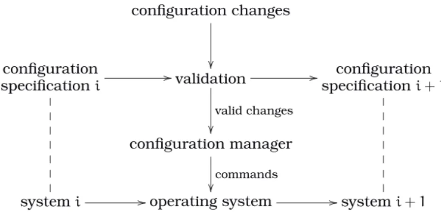
We adopt the reconfiguration model developed in [KM85, KM90] and summarised in Figure2.1on the next page1. In the following we describe the assumptions made by the model for each element appearing in the diagram.
A system can be depicted as a directed graph whose nodes are the system compon-ents and whose arcs are connections between componcompon-ents. The model assumes there is at most one connection between any pair of components. A transaction is a sequence of one or more message exchanges along a connection. An arc from a nodeN to a node
N′ states that all transactions along that connection are initiated byN, although during a transaction communication flow can occur in both directions. Transactions complete in bounded time and the initiator is always informed of completion. In particular, the system does not get into any deadlock or livelock situation. These assumptions help to prove that the consistent state can be reached in finite time and that the configuration manager knows when. A transaction t is dependent on the consequent transactions
configuration changes
configuration
specificationi //
validation // valid changes
configuration specificationi+1
configuration manager
commands
systemi //operating system //systemi+1
Figure 2.1: The dynamic reconfiguration model
t1, t2, . . . (writtent/t1t2. . .), if its completion depends on the completion of all the other ones. Otherwise a transaction is calledindependent.
Changes to a system are specified using four commands, to be executed by the op-erating system, with obvious meanings: createN,removeN,linkN toN′,unlinkN fromN′. Given a specification of the current system configuration and the specification of the configuration changes, the validation process checks whether the changes may be (totally or partially) applied to the system and produces the specification of the result-ing system. Checks may range from simple syntactic ones (e.g.,remove N is incorrect if N does not exist in the system) to deep semantic results (e.g., is the resulting sys-tem deadlock free?). In the following it is assumed that changes are valid and that the specification is declarative, i.e., the change commands are not in any particular order.
Given the valid changes, the configuration manager generates the instructions for the operating system to reconfigure the current system, such that the resulting one conforms to the specification produced by the validation process. In particular, the manager performs the following steps:
1. Compute from the change specification the nodes that must be in a consistent state for reconfiguration to take place.
2. Compute the nodes that must become “frozen” in order to achieve consistency over the set of nodes obtained in the previous step.
3. Send a “freeze” message to each node obtained in step 2 and wait for all the ac-knowledgments.
4. Instruct the operating system to execute changes in the following order: unlink,
remove,create,link.
5. Instruct the created and the “frozen” nodes (except the removed ones) to resume processing.
2.1 The Original Model 11
C1 s1/r1
/
/A1 r1/p
*
*
T T T T T T
M p //S C2
s2/r2
/
/A2 r2/p
4
4
j j j j j j
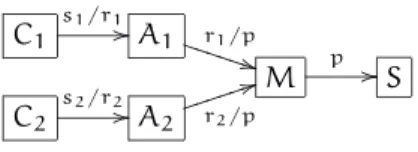
Figure 2.2: A client-server system with dependent transactions
N1 d
o
o
a/b
/
/N
2 b // c/d
o
o
Figure 2.3: Mutual dependencies
2.1.1
The Passive Approach
In this method [KM90] the “frozen” state is called passive and the “freeze” message is
passivate. To facilitate exposition, let us first handle only independent transactions. A component is passive if it is not engaged in transactions it initiated and if it will not start new ones. However, it must accept and service transactions in order to let other nodes become passive. Therefore, passiveness is reachable in finite time: a component just has to wait for the transactions it initiated to finish (this is guaranteed to happen) and then make sure it will not start new ones. The passive state is just a necessary condition for reconfiguration. In order to guarantee a consistent and stable internal state, in addition to being passive a node should not have any outstanding transaction to service. This is calledquiescenceand depends on those components that can initiate transactions with the node. Therefore, thepassive set of a nodeQ,PS(Q), is defined as
Qand all nodes with connection arcs towardsQ. It is easy to see thatQ is quiescent if all nodes inPS(Q)are passive.
The quiescent set QS for a given change specification is the set of nodes that must
be quiescent during the reconfiguration, namely those that will be removed and the initiators of transactions that will be added or removed. Newly created nodes are auto-matically quiescent. The set of nodes to “freeze”, called change passive set, is then simplyCPS=Si∈QSPS(i).
To see why this does not work for dependent transactions, consider a system with clients Ci accessing through agents Ai a server S managed by M (Figure 2.2). If the server is going to be replaced, then bothSandpwill be removed. Thus the configuration manager calculates QS = {M, S} and CPS = {A1, A2, M, S}. However, if a client has a new request si, then the respective agent cannot service it because according to the definition of passiveness it may not initiate ri (on which si depends). This would lead to a partially incomplete transaction, i.e., to an inconsistent state of the whole system during reconfiguration. On the other hand, allowing Ai to start transaction ri would lead to new transactions on the manager and on the server, which therefore would not be in the quiescent state.
Another problem is that reachability of the quiescent state in bounded time is lost. For example, if A1 is to be replaced, then QS = CPS = {C1, A1}. If A1 becomes pass-ive beforeC1, and C1 just initiates a new transaction s1 before getting the passivate command from the configuration manager, then the client will never become passive because r1 is not initiated. In this case one could order the commands (passivate
C1 before passivate A1), but for systems with mutual dependencies like the one in Figure2.3no such ordering is possible.
N2 d
/
/
a/bc
/
/N1 b/dmm66
m m m m
c/eQQQ(( Q Q Q
N3 e //
=⇒
a/de
/
/N d //
e //
Figure 2.4: Composing dependencies
of passive set must also change, since the nodes that may initiate transactions with a given node are not just its immediate neighbours. The new definitions are thus as follows.
In the generalised passive state a node is not engaged in non-consequent transac-tions it initiated and it will not initiate new ones. Furthermore the node accepts and services all requests, initiating consequent transactions if necessary. Theenlarged
pass-ive setof a nodeQ,EPS(Q), includesQand all nodes that can initiate transactions which
result in consequent transactions onQ.
Notice that both definitions reduce to the old ones in case all transactions are inde-pendent. The reconfiguration algorithm remains the same, except thatPS(i)is substi-tuted byEPS(i)in the calculation ofCPS.
The server replacement in Figure2.2on the preceding page is now correctly handled. SinceEPS(S) ={C1, A1, C2, A2, M, S}, all nodes have to be passivated. Even if all compon-ents butC1are already passive, any pendings1transaction will be serviced (throughA1 andM) by the server and therefore the client can become passive and reconfiguration may start.
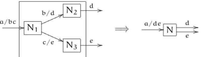
In general, systems are not flat as assumed until now but hierarchic, i.e., some nodes (calledcomposite) are made of connected subnodes. A composite node is connected to other nodes through some of its subcomponents. The transaction dependency of a com-posite component must be derived from its subcomponents. The following substitution rule is given in [KM90]:
“in composing two nodes, substitute the consequents for each occurrence of the dependent transaction which is hidden by the composition.”
The rule can be iterated on components and connections (Figure 2.4). To simplify re-configuration management, [KM90] suggests that a composite node is considered to be passive if all its subnodes are, and that all transactions between composite nodes are independent.
2.1.2
The Blocking Approach
An alternative method is presented in [GK96]. It assumes that a node is consistent and self-contained except during transactions, as those are the only interactions with the outside environment. Thus, to make a node quiescent it is enough to block it while it is idle (not engaged in any transaction). A component is also assumed not to interleave transactions: while handling a request a node may not service any new one, even if it comes from a different connection, and it may initiate only consequent transactions. This is used to prove that the blocked state is reachable in finite time.
2.1 The Original Model 13
B
A
1
o
o
BSet
E
2
? ? ? ? ? ? ? ?
C n //D Goo 1 F
Figure 2.5: A blocking problem
arrive and N will remain blocked. The basic question is therefore: what transactions should a blocked node service?
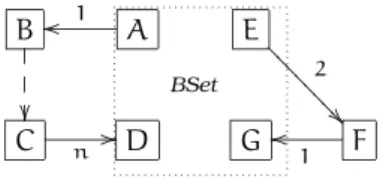
It is obvious that it cannot process just any incoming transaction, since it might come from a node that is not affected in any way by the reconfiguration and as such might initiate a new transaction any time. Thus the blocked node would have to unblock unpredictably and the safe state needed for reconfiguration to begin would never be reached. It is also evident that at least the transactions initiated by other BSet members will have to be serviced in order for them to become blocked. On the other hand, not every request from a non-BSet member can be ignored. Consider the cases depicted in Figure2.5. Node Dmust service the request from Cbecause it is the n-th consequent transaction of a transaction initiated byA, which must be completed for Ato become blocked. In the second case on the right half of the figure, componentF has initiated a transaction withGbefore getting a request fromE. IfGdoes not service the transaction,
Fwill never be able to start attendingE’s request since transactions do not interleave. One could let BSet nodes unblock just in those situations but the authors argue this is non-trivial and has great run-time overhead. Instead they propose the BSet to grow dynamically in step with outgoing transactions. When a node gets a request from a BSet member, it becomes a member too, and only requests from BSet members are attended; all other are queued and serviced after the reconfiguration. In the previous cases, it means that the BSet grows to encompass the whole system, and thereforeDandGwill service the transactions initiated byCandFrespectively.
Notice that the BSet has two kinds of members: those that “really” must block due to the reconfiguration and those that block in order to let members of the first kind to get blocked. Therefore a distinction is made between the original BSet and the extended BSet. Their union is the BSet. When all the original BSet nodes become blocked, the components in the extended BSet can be unblocked. The disruption thus first grows and then shrinks.
2.2
Discussion
The authors of the approaches just described discuss their results, but since [GK96] contains not a single example, comparison with [KM90] is stated in brief and vague terms. Since we use the same framework, we take a closer look at the two different methods in order to gain a better insight into the reconfiguration process to achieve further reduction in disruption. Both approaches are analysed in terms of disruption, run-time overhead, implementation, and how they deal with hierarchic systems.
2.2.1
Implementation
In the first approach the application programmer is expected to provide code that allows the component to reach the passive state and keep it, whereas in the second approach this happens transparently due to the added assumption that nodes are consistent when there are no interactions with the rest of the system. Of course, the other side of the coin is that the implementation is hidden away into the hooks which must trap low level events like message arrival.
On the other hand, the first approach requires just onepassivatemessage for each node in the extended passive set, while the second method generates initially |PSet0| messages and then1+|PSeti|messages for the addition of thei-th member of the exten-ded BSet. Also, the messages in the static method are just tokens, while those in the dynamic approach are descriptions of (potentially large) sets. The blocking approach has thus much greater run-time overhead and is more complex to implement, but imposes less burden on the component programmer.
2.2.2
Disruption
The important point in any dynamic reconfiguration method is that the “freezing” of a nodeNdoes not prevent other nodes from reaching their “frozen” state. Basically, both approaches solve the problem by “freezing” also every node that depends on N or on which N depends. This does not minimise disruption and in fact may involve many components besides those that are affected by reconfiguration.
To illustrate the differences between both approaches, let us apply them to common examples. We writeOBS and EBS for the original and the extended BSet, respectively. The first example is the system of Figure2.2on page11. If the server is to be replaced, we have seen that the first approach passivates all nodes. The second method considers
OBS = {M, S}, EBS = {} and PSet = {S}, because the only outgoing transaction from a BSet member ispand goes to the server. This means that on occurrence ofp,EBS={S}
and on its completion bothM andS block because they are idle and in the BSet. No-tice that the clients are not blocked and therefore may initiate new transactions during reconfiguration. SinceM is blocked, it will queue the requests and service them after the changes done to the system. This was considered an inconsistency in the passive approach, but in our opinion this is perfectly acceptable because the server manager has not been changed. Therefore its interface with the agents and the new server is the same as previously. This means that the new server is able to attend requests sent to the old one. To sum up, the blocking approach causes less disruption. The reason is that a passive node is active regarding transactions it services. Therefore, to achieve quiescence the node must be “shielded” from outside requests and that shield (the ex-tended passive set) must remain during reconfiguration. No such shield is required in the second approach since the components actually stop.
2.2 Discussion 15
transaction terminates, C1 will become passive and automatically quiescent. Recon-figuration can start, while all other components remain active. Applying the blocking approach one has OBS = {C1}, PSet0 = {A1}, EBS0 = {}. If there is a pending client re-quest,EBS1={A1}andPSet1={M}. Since the transaction is dependent, after two more stepsEBS3={A1, M, S}. In other words, to replace a client, the server is blocked (even if temporarily)! In this example the first approach causes much less disruption, contrary to the claim in [GK96] that the blocking approach performs always at least as well as the passive method. The reason is that the blocking approach is purely dynamic: it does not precompute the dependencies between nodes, which is essential to determine whether the blocking of two components will interfere with each other. Therefore at run-time the method goes throughall the nodes anOBSmember depends on, which form theEBS. If the configuration manager would compute the paths betweenOBSmembers, disruption could be greatly reduced in most cases.
The last example is the left half of the system in Figure 2.5 on page 13. In the second approach, ifAis not engaged in any transaction withB, it will block immediately. Thus as soon asD is idle it will get blocked too and reconfiguration starts. In the first approach, all nodes from B to C will be passivated even if no dependent transaction will occur. This is the advantage of a dynamic method. It only takes into account transactions that are actually occurring in the running system, while a static analysis must involve all transactions thatmay occur.
The authors have concentrated on the number of nodes that are passivated or blocked by their methods, but we think that indirect disruption must also be taken into account. Since a blocked node does not any processing whatever, any transaction it services or initiates unrelated to the reconfiguration will also be stopped and that may lead to (par-tial) inactivation of other components. Since passive nodes still service requests they cause indirect disruption in smaller scale. But internal processing that requires initi-ation of transactions is still hindered. This is recognised in [KM90]. The authors observe that the replacement of the server in Figure2.2 on page 11passivates the clients thus stopping them from interacting with other nodes not shown on the figure. Therefore, they should only be passive with respect to the server being replaced, not other nodes unrelated to the change. This could be achieved by distinguishing the relevant con-nections and modeling their state (connected-passive, connected-active, disconnected). This would allow more granularity, but the authors argue it would lead to more com-plex substates and more comcom-plex actions to obtain consistency since the nodes would be partially active. Therefore they conclude that their approach, while not minimal, is simple and sufficient.
In our opinion there is another factor that contributes to a greater disruption than necessary in some cases: the requirement for quiescence of the initiator node in (un)link changes.
Let us assume that the change specification contains a command unlink N from N′ for a non-consequent transaction. It is not necessary for N to be quiescent. It is
enough to be passive, thus not starting any new transaction withN′. Consider the right subsystem of Figure2.5 on page13where connection 1 will be removed. IfF∈QSthen
Eand every node that depends on transaction 2 would be inEPS. Therefore they and all nodes on which they can initiate transactions would be partially inactive. IfFwere only passivated, the extended passive set would not include the other nodes, reducing direct and indirect disruption greatly.
Both approaches measure disruption only in terms of nodes, neglecting the time factor. In the configuration model described in Section2.1on page9, first components are “frozen”, then change commands are applied, and finally components are activated. This does not minimise disruption time because each phase can only begin after the previous one ended. Moreover, commands are performed in a fixed sequence (first all
unlink, then all remove, etc.). It is obvious that in many cases some changes are independent of others. In those cases a part of the system might be changed without having to wait for nodes in other parts to be “frozen”, or commands of different kinds might be performed in parallel.
2.2.3
Hierarchic Systems
In [GK96] no reference is made to hierarchic systems. In fact, the blocking approach does not work for them since a composite node will in the general case interleave trans-actions, because its subcomponents run in parallel. As written before, [KM90] deals with such systems but their treatment is still very sketchy. Basically, it only indicates how to compute a composite node’s dependencies from its subcomponents. From there the extended passive set at the higher level can be computed. If the composite node has to be passivated, all its subcomponents must also. This certainly does not minim-ise disruption. We also feel that requiring independent transactions between composite components (as in CONIC[MKS89]) to reduce the number of those to be passivated may lead to extremely large components or to many small ones. In any case it may force the system designer to partition the system into artificial composite components that are uneasy to work with. But more importantly, [KM90] does not deal with the interaction between changes at different levels or how changes at a lower level will affect higher levels of the component hierarchy.
2.3
The Refined Model
Although the original analysis of the requirements for dynamic configuration [KM85] stressed the importance of modularity and well-defined component interfaces, the model presented in [KM90] does not provide any details about it. However, the concrete con-figuration language presented in [KM85], CONIC, and its successor DARWIN [MDEK95] provide a mechanism to specify the communication points of a component, called ports. Our model will thus support that notion, too. An interface is just a set of ports, each being used either to initiate transactions or to receive requests. Since the environment has no access to the inner structure of a component, the programmer must provide in the interface the dependencies between initiator ports and recipient ports.
Definition 2.1. Anode interfaceis a triplehI, R, Diwhere
• Iis the finite set ofinitiator ports;
• Ris the finite set ofrecipient portssuch thatI∩R=∅;
• D⊆R×Iis theport dependencyrelation.
A system is simply a set of connected nodes, where a connection is given by an initi-ator port and a recipient port. To capture sound software engineering principles (mod-ularity, encapsulation, data hiding, etc.), a system has no access to the inner structure of its nodes; it knows only their interfaces.
2.3 The Refined Model 17
without loss of generality that there is only one arc between a given pair of components. A connection based approach like ours distinguishes individual transactions and thus one must allow several connections to be linked to the same port (but only one trans-action for any given pair of ports). This covers typical situations like client-server (all client transactions linked to same server recipient port) and broadcast (many transac-tions with common initiator port). To avoid deadlock, the connectransac-tions (together with the port dependencies) may form no cycle. Formally, there may be no closed sequence of alternating recipient and initiator ports such that every initiator port is linked to the succeeding recipient port which in turn depends on the next initiator port in the sequence.
Definition 2.2. Asystem is a pairhN, Tiwhere
• Nis a non-empty finite set of node interfaces;
• T ⊆ [
n∈N
In×
[
n∈N
Rn is the set oftransactions.
Anon-empty pathis a sequence of portsr1i1r2i2· · ·rmim withm > 0such that
• ∀j∈{1, . . . , m−1}hij, rj+1i ∈T;
• ∀j∈{1, . . . , m}∃n∈Nhrj, iji ∈Dn.
For every non-empty pathr1· · ·im one hashim, r1i 6∈T.
The original model assumes that the dependencies among transactions are given with the system. We feel that our notion of port dependency is more realistic and more flexible since it allows the system architect to work with components programmed by several people, which may not include himself. Besides, it is a more primitive notion because the dependencies among connections can be computed from those between ports: if recipient port r depends on initiator port i, then any transaction received by r starts a transaction (i.e., depends) on every connection from i. As in the original model, the inverse is not true: the component might start a transaction on port i without having received any request on port r. The transaction dependency relation is closed under transitivity.
Definition 2.3. Given a systemhN, Ti, the transaction dependency relation/⊆T ×T is defined ashi, ri/hi′, r′i⇔(∃n∈Nhr, i′i ∈D
n)∨(∃t′′∈T hi, ri/t′′∧t′′/hi′, r′i).
A transactiontisdependent (on the consequent transactiont′) if∃t′∈T t/t′,
other-wisetisindependent.
The acyclic condition on port paths can thus be restated as: transaction dependency is anti-reflexive.
Proposition 2.1. In a systemhN, Ti,∄t∈T t/t.
Proof. It is easy to see that whenevert/t′, witht=hi, riand t′ =hi′, r′i, there is a
non-empty path fromr toi′. It is immediate for the base case, and whenevert/t′′andt′′/t′, the non-empty pathsr· · ·i′′andr′′· · ·i′ can be concatenated, forming a new non-empty path. Therefore, if we hadt/t, the pathr· · ·iwould be cyclic: hi, ri=t∈T. ✓
To build modular architectures it must be possible to abstract systems into nodes which will be part of other systems. A system is encapsulated in a composite node by hiding part of the system’s ports. The dependencies of the remaining visible ones (i.e., the ports of the composite node) are given by the underlying system.
Definition 2.4. A composite node consists of an interface hI, R, Di and a system hN, Ti
• I⊆ [
n∈N
In;
• R⊆ [
n∈N
Rn;
• D={hr, ii ∈R×I|r i1· · ·rmi is a non-empty path inhN, Ti}.
Example 2.1. Consider the two-pass filter depicted below withPassn=h{in},{rn},{hrn, ini}i
forn=1, 2. The dotted lines indicate for each port of a composite node which is the cor-responding port of the contained system.
t1
/
/ r1
Pass1
hi1,r2i
i2 t2
o
o
Filter
Pass2
Sincer1i1r2i2 is a non-empty path, we have Filter=h{i2},{r1},{hr1, i2i}iand hence t1/t2. This shows how inner port dependencies entail outer transaction dependencies.
If a node is not decomposed into further nodes, then it is calledsimple. Formally, only its interface is available. A system ishierarchicif it contains at least one composite node. Strictly speaking, given a system it is impossible to know for any of its nodes whether it is simple or composite because the formal definition of a system only provides the node interfaces. Thus it is possible for a simple node to be changed into a composite one and vice-versa in a transparent manner to the system.
2.4
Minimising Disruption
From the long summary and analysis of the passive and blocking approaches it be-comes clear that to minimise disruption we must look for a static blocking method at the connection level. To ensure that blocking a connection will not prevent others from reaching the blocked state, we can use a previously mentioned idea: to order the exe-cution of “freeze” commands. This works at the connection level because transactions do not form cycles. Extending the execution ordering to all commands one can define precisely what changes may be performed in parallel to reduce disruption time.
2.4.1
The Connection Approach
The essence of our proposal is to block only those connections that will be removed. To block a connection its initiator node waits for any ongoing transaction (on that connec-tion) to finish and then simply does not start a new one. For this to work we assume, as in the original model, that a transaction finishes in finite time and that its initiator knows when it ends. A simple implementation might be the following. For each com-ponent, assign to each transaction Ti it might initiate a boolean variable blocked[i] initialised to false and a semaphoreS[i] to ensure that the transaction completes be-fore being blocked. Then substitute the transaction codeTi by
P(S[i]);
wait while blocked[i]; Ti;
V(S[i]);
2.4 Minimising Disruption 19
if msg.command = block then begin i := msg.arg; P(S[i]);
blocked[i] := true; V(S[i]); send(config_manager, blocked, i) end
This code can also be provided by three hooks if wished. One to be called on transaction begin, one on transaction end. These hooks must be explicitly called by the component’s programmer, passing the transaction identifier as argument. The third hook would be called transparently to the component on message arrival. Compared to the blocking approach, run-time overhead is small since only one simpleblockmessage per connec-tion is sent and acknowledged. However, the number of messages is usually larger than in the passive approach because each node to be removed has to receive as manyblock
messages as the connections it has.
Blocking a connection means that the node will not service any transaction that de-pends on the blocked one. To ensure that the blocking of one connection will not prevent other pending transactions to block, the configuration manager orders the blocking ac-cording to dependency: if transaction tdepends on t′ then the block message is sent to the initiator oft′only aftertis known to be blocking. This is always possible because transactions do not depend cyclically on each other.
Example 2.2. Consider again the client-server system of Figure 2.2on page 11. Let us
assume that C1 and the server will be replaced. Then s1 and p must block because they will be removed, butpcannot simply block at once because it may have to service a pending s1 request (or else s1 could never terminate and get blocked). Therefore, blockings1beforepwe are sure that the blocking state is reachable for each link. Also, any request received by managerMafterpblocked can be safely queued until the server has been replaced because it is known that any connection that depends onpand that had to block has already done so.
Notice that this method would not work if the server would be allowed to be simply removed without being replaced by a new one. In that case a partially completed s2 request could remain after reconfiguration: clearly an inconsistent state. We assume that the validation process has ruled out such cases. If a consequent transaction is removed, either a replacement connection is created or else the transactions which depend on the removed one are changed too.
The original reconfiguration model distinguished two kinds of commands: those that are given in the change specification (create, etc.) and those that are used to “freeze” the components (passivate, block). The former are common to the passive and blocking approaches, while the latter are specific to each approach. In our model the “freeze” command blocks a connection. Furthermore, as multiple transactions are allowed between the same pair of components, the syntax of the(un)link commands has to change slightly.
Definition 2.5. Acommandis either ofcreaten,removen,linkt,unlinktorblock t, wherenis a node interface andta transaction.
2.4.2
The Partial Order
To minimise disruption time, the precise execution of the commands issued by the configuration manager is given by a temporal order<: if c < c′ then command c′ can only be executed after command c has completed. Commands that are not related through the ordering can be executed in parallel. It is obvious that the order must include the following relationships:
2. A connection must be blocked before it is removed.
3. A node can only be removed after its connections have been removed.
4. A node can only be linked after its creation.
We will be conservative and impose a further restriction. In some systems it might not be necessary and thus further parallelisation can be achieved. Consider a simple system with a client linked through transaction c to a server. If the server is to be replaced then a new connection c′ is needed. However, since the client remains the
same, the communication protocol with the new server is the same as with the old one. Therefore,c′ is the same transaction asc and we feel it does not make sense to linkc′
before unlinkingc. Besides, it might lead to execution errors if the implementation of the client assumes that there is always only one connection on that particular port. The general rule is:
5. A connection for transactions initiated by a node can be established only if no more connections from it will be removed.
As can be seen by exhaustive inspection of all possible interactions between the existing kinds of commands (block, link, unlink, remove, create) no further rules are necessary since there are no other dependencies between the commands and thus they may run in parallel.
Definition 2.6. Given a set of commands C for a system hN, Ti, the command order
<⊆C×Cis the smallest relation that satisfies
1. blockt <blockt′ ift/t′ and∄blockt′′∈C t/t′′∧t′′/t′;
2. blockt <unlinkt;
3. unlinkhi, ri<removenifi∈In orr∈Rn;
4. createn <linkhi, riifi∈In orr∈Rn;
5. unlinkhi, ri<linkhi, r′i.
Since the configuration manager directly implements the command order, it is desir-able to avoid redundancy. Therefore the ordering is an immediate precedence relation: ifc < c′then there is no commandc′′such thatc < c′′< c′. Due to the nature of the five cases this could only happen withblockcommands (case 1). Therefore the definition above imposes the additional condition.
Example 2.3. Applying the definition to Example2.2on the page before, only 4 steps are
necessary to replace the first client and the server whereby each step consists of several commands executing in parallel:
1. createC1′,blocks1,createS′
2. unlinks1,blockp
3. links′
1(the connection fromC1′ toA1),removeC1,unlinkp 4. linkp′ (the connection fromMtoS′),removeS
2.5 The Configuration Manager 21
To summarise, a connection based approach is not only advantageous in terms of the number of parts being “frozen”, but also in terms of minimising disruption time. In fact, in the node based approaches several nodes have to “freeze” just to let those nodes that really matter for the reconfiguration to become quiescent. In practice this means that reconfiguration can only start after all nodes have “frozen”. We think it is possible to have rules that allow one to calculate the exact set of nodes that have to “freeze” for a given change command to be executed, but those rules would be much more complicated than those shown above. Given that in a connection based approach the number of parts to be “frozen” is much smaller, and that “freeze” and change commands can be better interleaved, we conclude that our method can reduce disruption time considerably.
2.5
The Configuration Manager
Since a configuration manager executes several commands with some dependencies among them, we observe that such a manager can be seen as a parallel system too, with components and transactions. The goal is to have a precise definition of a configuration manager for a given set of commands to be applied to a given system. In this way the same framework can be used both for managers and the systems they reconfigure. In particular, the definition to be obtained can serve as a basis for a straightforward im-plementation of configuration managers, although our main goal is to provide a system view of a manager. To facilitate exposition we start with flat systems.
2.5.1
Flat Systems
The basic idea is that each change command is implemented by a component, and connections between components make dependencies between the corresponding com-mands explicit. To be more precise, if c < c′ then the component corresponding to c′
will initiate a transaction with the component corresponding toc. The transaction can be seen as a request fromc′ to executec. Once the acknowledgment is received,c′ can execute. Ifc′depends on several commands it must wait for all its requests to be atten-ded. A command is executed only once, even if several other commands are connected to (i.e., depend on) it.
A component implementing a command c must therefore have two ports. The re-cipient portsc receives all requests from the successors ofc, i.e., those nodes that can only execute afterc. The initiator portpcsends requests to all predecessors ofcto start execution and waits for the acknowledgments. It is obvious thatsc depends onpc.
In some cases a command c does not depend on the execution of others. In other words, there is noc′ such thatc′< c. The inverse can also happen: noc′ depends onc.
For example, if connections are to be removed, there is always at least oneblock com-mand to be executed first (i.e., it depends on no other one) and at least oneblockto be executed last. In these cases the corresponding components only need one port. Instead of providing special component definitions we take a generic approach. The configura-tion manager has always one specialnopcomponent with one recipient port snop and
one initiator portpnop(like any regular component) but there is no dependency between
them. For any request received bysnop an acknowledgment is immediately sent.
Like-wise, any transaction linked to pnop is immediately started. To see why this works,
consider the case where there is no c′ such that c′ < c. Since c depends on no other command, it can execute at once. In other words, the fact thatchas no predecessor can be seen as its predecessor being the “empty” commandnop. Therefore, ifc’s predecessor portpc is linked to the successor portsnop, the request fromcis immediately attended