[Retracted Article] Load Dependent Wear Analysis of Manganese Steels - Inluence of Al
Content
Rahul Sinhaa*, Alok Kumar Mukhopadhyaya
Received: February 01, 2017; Revised: April 17, 2017; Accepted: May 27, 2017
In this paper inluence of load on change in weight loss (mg), hardness and wear transition of 0.12 wt.% Al-Mn-steel (Steel A), 0.35 wt.% Al-Mn-steel (Steel B) and Mn-steel (Steel C) has been examined. With the increase in load these steels shows remarkable decrease in weight loss due to change in surface microstructure from austenite to ε or ά - martensite which results in increase in hardness of material. With the increase in hardness transition in wear mechanism has been noticed. In future aspect these steel would prove to be better material as wear resistant liner in many industrial application.
Keywords: Wear; Mn-steel; hardness, Wear transition, Field emission scanning electron microscope
* e-mail: [email protected]
1. Introduction
The manganese steel (Mn-steel) material was derived from the investigation done by Robert Hadield’s in 18821. It shows great interest in many mechanical and mining engineering sectors. It has an exceptional features like resistant to corrosion, low density, high strain hardening, high strength and better elongation which attracts the industries to use it as wear resistant material. It is also called as austenitic steel as its manganese (Mn) content is at austenitic phase. This austenitic phase changes to martensite with application of load from low to high. The change in phase of austenitic steel depends on mechanical property of material. The mechanical property of Mn-steel material is based on the theories of dipole interaction (DI) and stacking fault energy (SFE)2. DI results in dynamic strain aging (DSA) which creates diiculty in dislocating Mn, a substitute atom in crystal structure, from its original position. It is due to the formation of attraction ield between carbon (C) and Mn. This enhances strain hardenability of material with the formation of strain induced martensite or deformation twins3. Whereas, according to SFE theory, the SFE acts as an interruption between C and Mn in crystal structure. SFE depends on grain size, temperature and material composition4. It is expected that SFE plays an important role in improving the wear resistant property of Mn-steel alloys5. In some cases, addition of Al in Mn-steel alloy improves SFE but it decreases wear resistant property of material but other cases were also observed where addition of Al improves wear resistant property in Mn-steel alloy6. Ascelrad et al7 performed abrasive wear investigations on Mn-steel alloy and reported that the wear resistance property of Mn-steel alloy decreases with the increase in wt.% of Al. Contrarily,
in two-body abrasion, addition of Al has been found to be beneicial in improving wear resistance due to improve in hardness of material8, 9, 10. Although in many literatures, a gap has been found which concerns with the change in wear behavior of Mn-steel alloy with change in wear mechanism and its efect on hardness which would be more beneicial to select materials for future applications. This paper aims to ind out the tribological efect of Al addition in Mn-steel alloy and selection of better material which can be used in future as wear resistant material.
1.1. About stacking fault energy
The stacking faults are an interruption in crystal plane structure of materials, the interruption carries the energy which is called as stacking-fault energy. The distance between the two interruptions is supported with the balance between the repulsive force and attractive force. The repulsive force is between the two partial dislocation is balanced with the attractive force as provided due to the surface tension of the stacking fault. Thus the stacking fault energy can be calculated from the distance between the two dislocations. Using XRD technique, the approximate value of SFE can be determined using peak shift method.
2. Experimental Procedure
2.1. Materials
For experiments on wear, the test specimens were prepared as per ASTM G99 standard. To prepare test specimens the 0.12 wt.% Al and 0.35wt.% Al added Mn-steel was melted in furnace and casted into ingot. It was then given solution treatment at argon atmosphere in a furnace for 6 hours at 1200 ºC. The
a Department of Mining Machinery Engineering, Indian Institute of Technology, Dhanbad, India
R
E
T
R
A
C
T
E
D
A
R
T
IC
steels used in this research work are presented in Table 1. The chemical compositions of material were determined from energy dispersive X-ray analysis (EDX) as attached with FE-SEM ZEISS Supra 55(Germany) with air lock chamber mainly used in scientiic research. Its resolution at 15kV is 0.8nm and at 1kV is 1.6nm with 120000× magniication. The acceleration voltage for the FE-SEM supra 55 ranges from 100V to 30kV with range of probe current varies from 12pA to 100 nA. The composition from a particular test specimen was determined at 5 diferent surface locations and the average value of the compositions was noted in the Table 1. This process was followed to determine the compositions from every prepared test specimens.
2.2. Tribological test and microstructure
Wear tests were conducted on a pin-on-disc tribo-meter at room temperature with the pin as the test specimen. The test specimen was assembled on pin-holder of the pin-on-disc tribo-meter. The surface contact of the test specimen was made on coal particles of 710 μm size with hardness value of 318 HV, as pasted on the disc. To paste the coal on the disc, the surface of the disc was coarse inished and adhesive was provided on its coarser surface. As the coal adhered to the surface of the disc, the disc was then given a mold treatment to ix the coal particles at discrete locations. The prepared disc samples were then used as a sliding medium for the test specimens. In wear test experiments, the weight loss is a function of sliding distance at diferent loads (5 N, 15 N, 25 N and 35 N). The wear tests were performed at sliding distance of 1000m, 1100m, 1200m, 1300m, 1400m, 1500m, 1600m, 1800m, 1900m and 2000m. At irst, 5N load was applied on the test specimens and weight losses were irst measured at 1000m and the worn out test specimens was replaced with the new sample, having the same material composition as was previously examined, to perform wear test at sliding distance of 1200m. Following the same procedure, the weight losses were measured for every step increase in sliding distance up to 2000m. In the same way, load was increased to 15N to measure weight losses at every step increase in sliding distance. This process was followed till the load was increased to 35N. Wear tests on each test samples were performed to measure weight loss in mg.
It was performed on the samples before starting the wear tests and after the wear tests done at load of 5N, 15N, 25N and 35N. In micro-hardness tests, load was considered as an important variable because the loss of material in terms of weight loss (mg) increases with the increase in load at every step increase in sliding distance for every wear tests performed to measure weight loss (mg) with respect to particular sliding distance. To examine the microstructure, all the pin samples were washed with acetone after etching to examine its microstructure. Etching was done for 90 seconds by using 5% Nital.
3. Results and Discussion
3.1. Analysis on microstructure
The microstructure of material is presented in Figure 1. Microstructure for Steel-A have equiaxed austenitic grains with mean grain size of 281.4 ± 61.1 μm. Steel-B is having annealing twins with mean grain size as 142.3 ± 31.1 μm, and Steel-C is having mean grain size as 359.8 ± 70.9 μm.
3.2. Tribological test
Figure 2 describes the variations of weight losses of test specimens which are Steel-A, Steel-B and Steel-C. Results of weight loss of each test samples are presented in Figure 2. In Figure 2, at 5N load and 1000m sliding distance, the weight loss of Steel-B is very less as compared to Steel-A and Steel-C. As the load increases (15N, 25N and 35N) for sliding distance of 1000m, the weight loss of all the steels increases. Similar results have been observed for the weight losses measured at sliding distance of 1200m and 1400m and by increasing the load from 5N to 35N. At sliding distance of 1600m and increase in load from 5N to 35N, the measured weight losses for Steel-C were more as compared to Steel-A and Steel-B. At sliding distance of 1700m, with the increase in load the measured weight losses of Steel-A is less as compared to Steel-B and Steel-C. At sliding distance of 1800m and 35N load, the weight loss for Steel-B is less as compared to Steel-A and Steel-C. Further, at sliding distance of 1900m and 2000m, the weight loss for Steel-B was observed to be less as compared to Steel-A and Steel-C.
Table 1. Chemical composition and SFE of the steels used in this study.
Steels C Mn S Si P Cr Al Approximate range of SFE
Steel-A 1.07 12.49 0.02 0.52 0.03 0.07 0.12 15-21
Steel-B 1.07 12.49 0.02 0.52 0.03 0.07 0.35 18-35
Figure 1. Microstructre of: (a) 0.12wt.% Al added Mn-steel, (b) 0.35wt.% Al added Mn-steel and (c) Mn-steel material with no Al added.
Figure 2. Weight loss at diferent load for: (a) Steel-A, (b) Steel-B and (c) Steel-C.
R
E
T
R
A
C
T
E
D
A
R
T
IC
L
increase in load for every step increase in sliding distance. In this study, wear of Steel-B was less as compared to wear of Steel-A and Steel-C. This can be said that addition of Al is desirable in Mn-steel alloy.
However, it is diicult to say that SFE has some relation with the material. Although, from Table 1, the value of SFE for Steel-B ranges between 18-35 which is approximately more than the two Steels, i.e. Steel-A and Steel-C. Also, the obtained results of weight loss for all the steels, selected for wear study in this work, shows that Steel-B has better result than the two steels. Thus, the addition of Al is more efective in the study as it improves the SFE as well as reduces the weight loss of material. But still more investigations are needed to validate the hypothesis, about decrease in material loss due to SFE, as some researchers have reported that the decrease in material loss is a function of microstructural properties of the steels. Coronado et al11 has reported that as the austenite phase of austenitic steel is unstable at high load it changes to martensite with increasing load.
3.3. Wear mechanisms
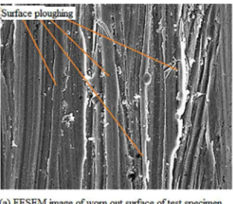
The wear mechanism observed under ield emission scanning electron microscope (FESEM) for all steels is
Figure 3. Field emission scanning electron microscope images of worn out surface of Steel-A test specimen at: (a) 5 N, (b) 15 N, (c) 25 N and (d) 35 N.
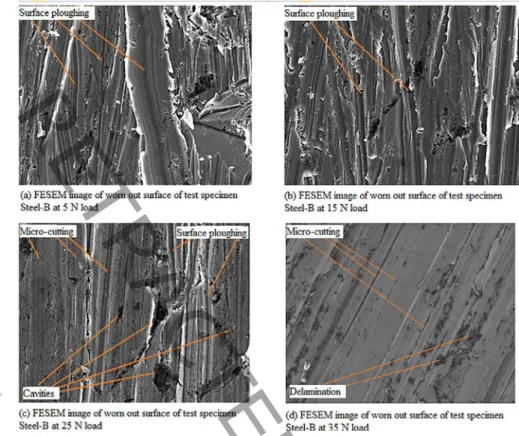
Figure 3(b), Figure 4(b) and Figure 5(a), there is an emergence of micro-cutting or scratches along with surface ploughing or surface deformation at 15 N load. This converts the wear mechanism from surface ploughing, as observed under low load, to micro-cutting as observed. The change in wear mechanism is having similarity with the results of Kitsunai et al12. They reported in their work about the transitions in wear mechanism with the increase in load. According to the work of Childs13, the steel shows work hardening behavior at higher load in abrasion which results in increase in more energy for cutting surface of work hardened steel. This creates diiculty in removing the material by micro-cutting. Steel with low SFE value have less removed material in abrasion process than with the material with high SFE14.
3.4. Hardness test
Results of Vickers hardness values (in kg/ mm2) for the Steel-A, Steel-B and Steel-C are shown in Figure 6. From Figure 6, initial hardness of Steel-A is more as compared to the Steel-B and Steel-C. The hardness property of material is obtained with the quenching process. As the Steel-A was quenched in water and water provides faster cooling rate than oil which improves the initial hardness of Steel-A. For
R
E
T
R
A
C
T
E
D
A
R
T
IC
Figure 4. Field emission scanning electron microscope images of worn out surface Steel-B test specimen at: (a) 5 N, (b) 15 N, (c) 25 N and (d) 35 N.
Figure 5. Field emission scanning electron microscope images of worn out surface Steel-C test specimen at: (a) 5 N, (b) 15 N, (c) 25 N and (d) 35 N.
R
E
T
R
A
C
T
E
D
A
R
T
IC
L
Figure 6. Results of micro-hardness test before and after wear tests for Steel-A, Steel-B and Steel-C.
the results of hardness tests for Steel-B and Steel-C, the Steel-B has slight variations in hardness of Steel-C. This shows that Steel-B is having very similar hardness property as of Steel-C. The slight variations in hardness are due to ductile behaviour of Steel-B as obtained after oil quenching. The Steel-A can be used as wear resistant material where hardness is an important factor in industries.
Also, from the obtained results of hardness tests it is clear that with the increase in load, weight loss of material decreases. Thus, weight loss depends on the material property. The decrease in weight loss is a function of twins formation as ε or ά – martensite (or induced martensite)15. In tribological analysis, the Steel-A gave less diference between the initial and inal hardness. The rapid change in hardness for Steel-A is the result of grain reinement which is due to SFE and dipole interaction. The change in microstructure of material reduces material losses. The progress of work hardening is followed by transition in wear mechanism which was also reported by Garisson (1987) in his work for the hardened steel material16. Wert et al17 reports that change in wear mechanism depends on hardness of the material. In the present study, transition in wear mechanisms were obtained with the variation in load and results of hardness test explores that wear behavior is a function of material properties which changes with the increase in load. According to Ashby et al18, the two mating surfaces have unlimited number of asperities and valleys which separates the two mating surfaces with it, Figure 7. During loading and abrasions of two mating surfaces, the weak asperities break out due to shear failure. For the material like austenitic steel, the C-Mn interaction resist in shear failure due to accretion of dynamic equilibrium between C-Mn. This makes the asperities to deform and results in removal of surface material in cyclic abrasion process. After the complete removal of weak layers, new surfaces are formed with improved surface hardness19.
4. Conclusions
In wear tests, all the selected steel (Steel-A, Steel-B and Steel-C) shows remarkable decrease in weight losses. At low load and minimum sliding distance, the steels have minimum weight losses. The weight losses increases with sliding distance but when higher load is applied on the steels, the weight loss starts decreasing. From the work performed under FESEM on worn out test specimens of steels, the wear mechanism shows transitions from surface ploughing to micro-cutting. The change in wear mechanisms after abrasion is due to formation of new surface layers which results in more hardened surface on the steels and weight loss has been observed to be decreasing at higher load.
Results shows that weight loss of Steel-B is less than Steel-A and Steel-C and it can be considered as an important wear resistant material where less decrease in weight loss is considered. But as per the hardness is concerned, Steel-A has good initial hardness than Steel-B and it can be used in industries where hardness is an important factor in wear resistant material. This study will help many industries to select the better material for applications in large area.
5. References
1. Desch CH. Robert Abbott Hadield. 1858-1940. Biographical Memoirs of Fellows of the Royal Society. 1941;3(10):647-664.
2. Bayraktar E, Khalid FA, Levaillant C. Deformation and fracture behaviour of high manganese austenitic steel. Journal of Materials Processing Technology. 2004;147(2):145-154.
3. Kim H, Su DW, Kim NJ. Fe-Al-Mn-C lightweight structural alloys: a review on the microstructures and mechanical properties. Science and Technology of Advanced Materials.
2013;14(1):014205.
4. Song W, Ingendahl T, Bleck W. Control of Strain Hardening Behaviour in High-Mn Austenitic Steels. Acta Metallurgica Sinica (English Letters). 2014;27(3):546-556.
5. Gutierrez-Urrutia I, Raabe D. Grain size efect on strain hardening in twinning-induced plasticity steels. Scripta Materialia.
2012;66(12):992-996.
6. Acselrad O, de Souza AR, Kalashnikov IS, Camargo Jr. SS. A irst evaluation of the abrasive wear of an austenitic FeMnAlC
steel. Wear. 2004;257(9-10):999-1005.
7. Coronado JJ, Sinatora A. Efect of abrasive size on wear of metallic
materials and its relationship with microchips morphology and wear micro-mechanisms: Part 1. Wear. 2011;271(9-10):1794-1803.
8. Feller HG, Gao B. Correlation of tribological and metal physics data: the role of stacking fault energy. Wear. 1989;132(1):1-7.
9. Dumay A, Chateau JP, Allain S, Migot S, Bouaziz O. Inluence of addition elements on the stacking-fault energy and mechanical properties of an austenitic Fe–Mn–C steel. Materials Science and Engineering: A. 2008;483-484:184-187.
10. Saeed-Akbari A, Imlau J, Prahl U, Bleck W. Derivation and Variation in Composition-Dependent Stacking Fault Energy Maps Based on Subregular Solution Model in High-Manganese Steels. Metallurgical and Materials Transactions A. 2009;40(13):3076-3090.
11. Coronado JJ, Rodríguez SA, Sinatora A. Efect of particle hardness on mild-severe wear transition of hard second phase materials. Wear. 2013;301(1-2):82-88.
12. Kitsunai H, Kato K, Hokkirigawa K, Inoue H. The transition between microscopic wear modes during repeated sliding friction observed by a scanning electron microscope tribosystem. Wear.
1990;135(2):237-249.
13. Childs T. The Mapping of Metallic Sliding Wear. Proceedings of the Institution of Mechanical Engineers, Part C: Journal of Mechanical Engineering Science. 1988;202(6):379-395.
14. Zuidema BK, Subramanyam DK, Leslie WC. The efect of aluminium on the work hardening and wear resistance of hadield manganese steel. Metallurgical Transactions A.
1987;18(9):1629-1639.
15. Sin H, Saka N, Suh NP. Abrasive wear mechanisms and the grit size efect. Wear. 1979;55(1):163-190.
16 Garrison WM Jr. Abrasive wear resistance: the efects of ploughing and the removal of ploughed material. Wear. 1987;114(2):239-247.
17. Wert JJ, Singerman SA, Caldwell SG, Quarles RA. The role of stacking fault energy and induced residual stresses on the sliding wear of aluminium bronze. Wear. 1983;91(3):253-267.
18. Ashby MF, Abulawi J, Kong HS. Temperature Maps for Frictional Heating in Dry Sliding. Tribology Transactions.
1991;34(4):577-587.
19. Chaudhuri DK, Xie D, Lakshmanan AN. The inluence of stacking fault energy on the wear resistance of nickel base alloys. Wear. 1997;209(1-2):140-152.